ON THIS PAGE
Configure SD-WAN with Active/Standby Connection to the Internet on an SRX300 Services Gateway
Requirements
This example uses the following hardware and software components.
One SRX300 series devices (320, 340, 345, 380)
One Wi-Fi MPIM for SRX300 series
One LTE MPIM for SRX300 series
One SIM card with subscription for data services
Junos OS 19.4R1
Overview
In this example, we are setting up a branch SRX320 Series device to provide wired and wireless Internet and Intranet access to the employees on-site, as well as wireless Internet access to guest devices. The primary internet link is through Ethernet while the backup connectivity is through the LTE network. The two links are configured in Active/Standby mode, whereby no traffic is routed through the LTE modem, unless the primary link is down.
Topology
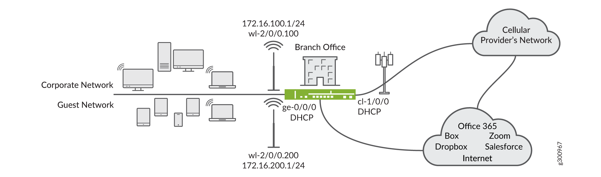
The topology of the example is shown in Figure 1. The LTE Mini-PIM is installed in slot 1. The WI-FI Mini-PIM is installed in slot 2. The SIM card is installed in slot 1 of the LTE module. The primary link is connected to interface ge-0/0/0 and it receives its IP address, network mask, default gateway and DNS servers from the device that it is connected to. The modem has interface cl-1/0/0.
The PDP context is terminated on interface dl.0 and, similarly to ge-0/0/0, the IP address, network mask and default gateway are assigned by the GGSN/PGW. The Wi-Fi interface is wl-2/0/0.200 serves the guest network, while interface wl-2/0/0.100 serves the corporate network. The security zones and the lists of interfaces for each zone are shown in Figure 2.
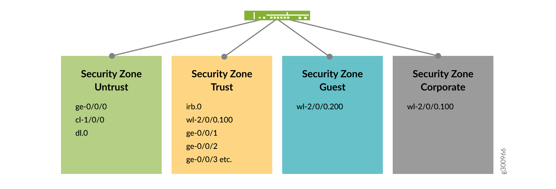
There are four security zones configured on the SRX300 series device, specifically Untrust, Trust, Corporate and Guest. The separation of the interfaces into security zones enables the separation of traffic and mitigates the risks the corporate Intranet is exposed to and serves as a vehicle to achieve clear and simplified implementation of security policies. Zone Untrust hosts the interfaces that have access to the Internet.
The internal interfaces in the corporate Intranet are in zone Trust. The organization wireless devices roam in zone Corporate. The personal mobile devices, which are granted Internet access only, are in zone Guest.
Table 1 shows the desired behavior of the security policies for traffic between zones.
From-To |
Untrust |
Trust |
Corporate |
Guest |
|---|---|---|---|---|
Untrust |
No |
Trust-initiated only |
Corporate-initiated only |
Guest-initiated only |
Trust |
Yes |
Yes |
Corporate-initiated only |
No |
Corporate |
Yes |
Yes |
Yes |
No |
Guest |
Yes |
No |
No |
No |
The VLAN information and the IP address information for the interfaces is summarized in Table 2.
Interface |
VLAN |
IP Adress |
Netmask |
|---|---|---|---|
wl-2/0/0.100 |
100 |
172.16.100.1 |
255.255.255.0 |
wl-2/0/0.200 |
200 |
192.16.200.1 |
255.255.255.0 |
dl.0 |
3 |
DHCP |
- |
ge-0/0/0 |
3 |
DHCP |
- |
Irb.0 |
3 |
192.168.1.1 |
255.255.255.0 |
Configuration and Validation
Configuration
Step-by-Step Procedure
The steps in this configuration logically build from the lower layers to the upper layers.
Create a VLAN for the guest devices.
set vlans guest-ap vlan-id 200
set vlans guest-ap description "VLAN that hosts the guest devices in the Guest security zone"
Create a VLAN for the corporate devices.
set vlans corporate vlan-id 100
set vlans corporate description "VLAN that hosts the corporate devices in the Trust security zone"
Create an access point.
set wlan access-point branch-ap interface wl-2/0/0
set wlan access-point branch-ap location "TME Lab, Sunnyvale, CA"
Set the country where the device is installed. Different countries have different 802.11 spectrum available for general use.
set wlan access-point branch-ap access-point-options country US
Configure the 5GHz radio interface of the access point. Set its mode, the channel number it will operate on, and the bandwidth it will use. Also, set the transmit power for the 5GHz radio interface (in %).
set wlan access-point branch-ap radio 1 radio-options mode acn
set wlan access-point branch-ap radio 1 radio-options channel number 100
set wlan access-point branch-ap radio 1 radio-options channel bandwidth 40
set wlan access-point branch-ap radio 1 radio-options transmit-power 100
Create a virtual access point (VAP) for the 5GHz guest network. The Mini-PIM supports up to eight virtual access points per radio interface.
set wlan access-point branch-ap radio 1 virtual-access-point 0 description Guest
set wlan access-point branch-ap radio 1 virtual-access-point 0 ssid Guest
set wlan access-point branch-ap radio 1 virtual-access-point 0 vlan 200
Configure security for the VAP as
wpa-personal. Set the cipher suite, key type, and preshared key.set wlan access-point branch-ap radio 1 virtual-access-point 0 security wpa-personal wpa-version v2 set wlan access-point branch-ap radio 1 virtual-access-point 0 security wpa-personal cipher-suites ccmp set wlan access-point branch-ap radio 1 virtual-access-point 0 security wpa-personal key-type ascii set wlan access-point branch-ap radio 1 virtual-access-point 0 security wpa-personal key Juniper123
Configure the 2.4GHz radio interface of the access point. Set its mode, the channel number it will operate on, and the bandwidth it will use. Also, set the transmit power for radio interface (in %).
set wlan access-point branch-ap radio 2 radio-options mode gn
set wlan access-point branch-ap radio 2 radio-options channel number 6
set wlan access-point branch-ap radio 2 radio-options channel bandwidth 20
set wlan access-point branch-ap radio 2 radio-options transmit-power 100
Configure the VAP on the 2.4GHz guest network.
set wlan access-point branch-ap radio 2 virtual-access-point 0 description Guest
set wlan access-point branch-ap radio 2 virtual-access-point 0 ssid Guest
set wlan access-point branch-ap radio 2 virtual-access-point 0 vlan 200
Configure security for the VAP as
wpa-personal. Set the cipher suite, key type, and preshared key.set wlan access-point branch-ap radio 2 virtual-access-point 0 security wpa-personal wpa-version v2 set wlan access-point branch-ap radio 2 virtual-access-point 0 security wpa-personal cipher-suites ccmp set wlan access-point branch-ap radio 2 virtual-access-point 0 security wpa-personal key-type ascii set wlan access-point branch-ap radio 2 virtual-access-point 0 security wpa-personal key Juniper123
Configure the VAP on the 5GHz corporate network.
set wlan access-point branch-ap radio 1 virtual-access-point 1 description Corporate
set wlan access-point branch-ap radio 1 virtual-access-point 1 ssid Corporate
set wlan access-point branch-ap radio 1 virtual-access-point 1 vlan 100
Configure security for the VAP as
wpa-personal. Set the cipher suite, key type, and preshared key.set wlan access-point branch-ap radio 1 virtual-access-point 1 security wpa-personal wpa-version v2 set wlan access-point branch-ap radio 1 virtual-access-point 1 security wpa-personal cipher-suites ccmp set wlan access-point branch-ap radio 1 virtual-access-point 1 security wpa-personal key-type ascii set wlan access-point branch-ap radio 1 virtual-access-point 1 security wpa-personal key corpKey123
Configure the VAP on the 2.4GHz corporate network.
set wlan access-point branch-ap radio 2 virtual-access-point 1 description Corporate
set wlan access-point branch-ap radio 2 virtual-access-point 1 ssid Corporate
set wlan access-point branch-ap radio 2 virtual-access-point 1 vlan 100
Configure security for the VAP as
wpa-personal. Set the cipher suite, key type, and preshared key.set wlan access-point branch-ap radio 2 virtual-access-point 1 security wpa-personal wpa-version v2 set wlan access-point branch-ap radio 2 virtual-access-point 1 security wpa-personal cipher-suites ccmp set wlan access-point branch-ap radio 2 virtual-access-point 1 security wpa-personal key-type ascii set wlan access-point branch-ap radio 2 virtual-access-point 1 security wpa-personal key corpKey123
Create the IP interface that will act as default gateway for devices in the guest VAPs (one VAP works on 5GHz and the other one on 2.4GHz).
set interfaces wl-2/0/0 unit 200 vlan-id 200
set interfaces wl-2/0/0 unit 200 family inet address 172.16.200.1/24
Create the IP interface that will act as the default gateway for devices in the in the corporate VAPs (one VAP works on 5GHz and the other one on 2.4GHz).
set interfaces wl-2/0/0 unit 200 vlan-id 100
set interfaces wl-2/0/0 unit 200 family inet address 172.16.100.1/24
Create a security zone for the guest devices and allow DHCP and all other necessary protocols in it. Ensure that the proper wl interface is added to the zone as well.
set security zones security-zone guest host-inbound-traffic system-services dhcp
set security zones security-zone guest host-inbound-traffic system-services all
set security zones security-zone guest host-inbound-traffic protocols all
set security zones security-zone guest interfaces wl-2/0/0.200
Create a security zone for the corporate devices and allow DHCP and all other necessary protocols in it. Ensure that the proper wl interface is added to the zone as well.
set security zones security-zone corporate host-inbound-traffic system-services dhcp
set security zones security-zone corporate host-inbound-traffic system-services all
set security zones security-zone corporate host-inbound-traffic protocols all
set security zones security-zone corporate interfaces wl-2/0/0.100
Create a unique DHCP server group for the guest VAPs (only one server group is needed for both of the guest VAPs).
set system services dhcp-local-server group jdhcp-guest-group interface wl-2/0/0.200
Create a unique DHCP server group for the corporate VAPs.
set system services dhcp-local-server group jdhcp-corporate-group interface wl-2/0/0.100
Create a pool of IP addresses to be assigned to the devices, roaming in the guest VAPs. Set the lowest and the highest IP addresses to be assigned to devices from this pool, the DNS servers and the IP address of the default gateway for the pool.
set access address-assignment pool junosDHCPPoolGuest family inet network 172.16.200.0/24
set access address-assignment pool junosDHCPPoolGuest family inet range junosRangeGuest low 172.16.200.10
set access address-assignment pool junosDHCPPoolGuest family inet range junosRangeGuest high 172.16.200.200
set access address-assignment pool junosDHCPPoolGuest family inet dhcp-attributes name-server 8.8.8.8
set access address-assignment pool junosDHCPPoolGuest family inet dhcp-attributes router 172.16.200.1
Create a pool of IP addresses to be assigned to the devices, roaming in the corporate VAPs. Set the lowest and the highest IP addresses to be assigned to devices from this pool, the DNS servers and the IP address of the default gateway for the pool.
set access address-assignment pool junosDHCPPoolCorporate family inet network 172.16.100.0/24
set access address-assignment pool junosDHCPPoolCorporate family inet range junosRangeCorporate low 172.16.100.10
set access address-assignment pool junosDHCPPoolCorporate family inet range junosRangeCorporate high 172.16.100.200
set access address-assignment pool junosDHCPPoolCorporate family inet dhcp-attributes name-server 8.8.8.8
set access address-assignment pool junosDHCPPoolCorporate family inet dhcp-attributes name-server 1.1.1.1
set access address-assignment pool junosDHCPPoolGuest family inet dhcp-attributes router 172.16.100.1
Create source NAT to apply NAT to devices in the guest zone to the outer interface.
set security nat source rule-set guest-to-untrust from zone guest
set security nat source rule-set guest-to-untrust to zone untrust
set security nat source rule-set guest-to-untrust rule r1 match source-address 0.0.0.0/0
set security nat source rule-set guest-to-untrust rule r1 then source-nat interface
Create source NAT to apply NAT to devices in the corporate zone to the outer interface.
set security nat source rule-set corporate-to-untrust from zone corporate
set security nat source rule-set corporate-to-untrust to zone untrust
set security nat source rule-set corporate-to-untrust rule r-c2u-1 match source-address 0.0.0.0/0
set security nat source rule-set corporate-to-untrust rule r-c2u-1 then source-nat interface
Create a security policy that allows traffic between the Guest and Untrust zones. Make sure that the desired network segments and/or applications are included into the policy.
set security policies from-zone guest to-zone untrust policy allow-in-zone match source-address any
set security policies from-zone guest to-zone untrust policy allow-in-zone match destination-address any
set security policies from-zone guest to-zone untrust policy allow-in-zone match application any
set security policies from-zone guest to-zone guest policy allow-in-zone then permit
Create a security policy that allows traffic between the Corporate and Untrust zones. This step enables traffic that has NAT applied to flow between the zones.
set security policies from-zone corporate to-zone untrust policy internet-acces match source-address any
set security policies from-zone corporate to-zone untrust policy internet-acces match destination-address any
set security policies from-zone corporate to-zone untrust policy internet-acces match application any
set security policies from-zone corporate to-zone untrust policy internet-acces then permit
Create a security policy that allows traffic between the Corporate and Trust zones, and enables traffic that has NAT applied to flow between the zones.
set security policies from-zone corporate to-zone trust policy internet-acces match source-address any
set security policies from-zone corporate to-zone trust policy internet-acces match destination-address any
set security policies from-zone corporate to-zone trust policy internet-acces match application any
set security policies from-zone corporate to-zone trust policy internet-acces then permit
Set the description of the interface for primary Internet link. Set the interface to obtain configuration over DHCP protocol. Make sure the LTE interface is set as backup for the Internet link.
set interfaces ge-0/0/0 unit 0 description "WAN Interface 1 - Primary"
set interfaces ge-0/0/0 unit 0 family inet dhcp vendor-id Juniper-srx320
set interfaces ge-0/0/0 unit 0 backup-options interface dl0.0
Configure the modem interface. Ensure that the SIM slot, which contains SIM card, is set to active.
set interfaces cl-1/0/0 dialer-options pool 1 priority 100
set interfaces cl-1/0/0 act-sim 1
set interfaces cl-1/0/0 cellular-options sim 1 radio-access automatic
Configure the dialer interface.
set interfaces dl0 unit 0 family inet negotiate-address
set interfaces dl0 unit 0 family inet6 negotiate-address
set interfaces dl0 unit 0 dialer-options pool 1
set interfaces dl0 unit 0 dialer-options dial-string "*99#"
Configure the wireless interface to accept VLAN untagged packets.
set interfaces wl-2/0/0 flexible-vlan-tagging
Set the access point name for the SIM in the modem.
request modem wireless create-profile profile-id 10 access-point-name broadband cl-1/0/0 slot 1
Commit the configuration
Validation
Step-by-Step Procedure
Ensure that the interfaces are up and running.
> show interfaces terse
wl-2/0/0                up    up
wl-2/0/0.100            up    up   inet     172.16.100.1/24
wl-2/0/0.200            up    up   inet     172.16.200.1/24
wl-2/0/0.32767          up    up
Check the status of the access point and make sure that the status of the radio interfaces is ON, the channels and the bandwidths they operate on are as configured..
> show wlan access-points branch-ap detail
Active access point detail information

Access Point          : branch-ap
Type                  : Internal
Location              : TME Lab, Sunnyvale, CA
Serial Number         : EV2619AF0051
Firmware Version      : v1.2.8
Alternate Version     : v1.1.0
Country               : US
Access Interface      : wl-2/0/0
System Time           : Mon Mar 23 22:36:43 UTC 2020
Packet Capture        : Off
Ethernet Port:
    MAC Address       : 0c:81:26:58:04:26
Radio1:
    Status            : On
    MAC Address       : 0c:81:26:58:04:28
    Temperature       : 50
    Mode              : IEEE 802.11a/n/ac
    Channel           : 108
    Bandwidth         : 40
    Transmit Power    : 100
Radio2:
    Status            : On
    MAC Address       : 0c:81:26:58:04:27
    Temperature       : 52
    Mode              : IEEE 802.11g/n
    Channel           : 6
    Bandwidth         : 20
    Transmit Power    : 100
Check the status of all VAPs. Make sure that the SSIDs and the security settings are as configured.
> show wlan access-points branch-ap virtual-access-points all detail
Virtual access points information

Access point name: branch-ap
Radio1:
  VAP0:
    SSID                    : Guest
    Description             : Guest
    MAC Address             : 0c:81:26:58:04:28
    Maximum Station         : 127
    Broadcast SSID          : Enable
    Station Isolation       : Disable
    Upload Limit            : Disable
    Download Limit          : Disable
    VLAN ID                 : 200
    Station MAC Filter      : Disable
    VAP Security            : wpa-personal
    WPA Version:
      WPA2                  : Enable
      WPA                   : Disable
    Ciper-Suites:
      CCMP                  : Enable
      TKIP                  : Disable
    Traffic Statistics:
      Input Bytes           : 79470
      Output Bytes          : 99937
      Input Packets         : 479
      Output Packets        : 498
  VAP1:
    SSID                    : Corporate
    Description             : Corporate
    MAC Address             : 16:81:26:58:04:28
    Maximum Station         : 127
    Broadcast SSID          : Enable
    Station Isolation       : Disable
    Upload Limit            : Disable
    Download Limit          : Disable
    VLAN ID                 : 100
    Station MAC Filter      : Disable
    VAP Security            : wpa-personal
    WPA Version:
      WPA2                  : Enable
      WPA                   : Disable
    Ciper-Suites:
      CCMP                  : Enable
      TKIP                  : Disable
    Traffic Statistics:
      Input Bytes           : 2495033
      Output Bytes          : 3480274
      Input Packets         : 30241
      Output Packets        : 29412
Radio2:
  VAP0:
    SSID                    : Guest
    Description             : Guest
    MAC Address             : 0c:81:26:58:04:27
    Maximum Station         : 127
    Broadcast SSID          : Enable
    Station Isolation       : Disable
    Upload Limit            : Disable
    Download Limit          : Disable
    VLAN ID                 : 200
    Station MAC Filter      : Disable
    VAP Security            : wpa-personal
    WPA Version:
      WPA2                  : Enable
      WPA                   : Disable
    Ciper-Suites:
      CCMP                  : Enable
      TKIP                  : Disable
    Traffic Statistics:
      Input Bytes           : 2025
      Output Bytes          : 2603
      Input Packets         : 15
      Output Packets        : 19
  VAP1:
    SSID                    : Corporate
    Description             : Corporate
    MAC Address             : 16:81:26:58:04:27
    Maximum Station         : 127
    Broadcast SSID          : Enable
    Station Isolation       : Disable
    Upload Limit            : Disable
    Download Limit          : Disable
    VLAN ID                 : 100
    Station MAC Filter      : Disable
    VAP Security            : wpa-personal
    WPA Version:
      WPA2                  : Enable
      WPA                   : Disable
    Ciper-Suites:
      CCMP                  : Enable
      TKIP                  : Disable
    Traffic Statistics:
      Input Bytes           : 75308
      Output Bytes          : 70057
      Input Packets         : 498
      Output Packets        : 389
Check the summary about the client associations on each radio of the access point. This command shows the number of associated users on each radio interface.
> show wlan access-points branch-ap radio 1 client-associations
Access point client associations summary

Access point: branch-ap
Client number on radio 1 (5.0 GHz)  : 1
Check the details about the client associations on each radio of the access point. The MAC address of the users is shown in the output, as well as traffic statistics.
> show wlan access-points branch-ap radio 1 client-associations detail
Access point client associations information

Access point: branch-ap
VAP                                        Client MAC Address   Auth   Packets Rx/Tx   Bytes Rx/Tx
Radio1:Corporate                        24:77:03:80:52:68    OK     42501/25026     2579601/2742637
Check if the Mini-PIM modules are detected by Junos.
> show chassis hardware
Hardware inventory:
Item             Version  Part number  Serial number     Description
Chassis                                CX0916AF0004      SRX320-POE
Routing Engine   REV 0x05 650-065041   CX0916AF0004      RE-SRX320-POE
FPC 0                                                    FPC
  PIC 0                                                  6xGE,2xGE SFP Base PIC
FPC 1            REV 02   650-073958   AH06074206        FPC
  PIC 0                                                  LTE for AE
FPC 2            REV 03   650-096889   EV2619AF0051      FPC
  PIC 0                                                 WAP for WW mPIM
Power Supply 0
Check the firmware version of the Mini-PIMs and update it if needed.
> show system firmware
Part             Type              Tag Current               Available             Status
                                       version               version
FPC 1
PIC 0            MLTE_FW           1   17.1.80              0                     OK
FPC 2
PIC 0           MWAP_FW           1   1.2.8                 0                     OK
Routing Engine 0 RE BIOS           0   3.0                   3.6                   OK
Routing Engine 0 RE BIOS Backup    1   3.0                   3.6                   OK
Get a packet capture on a VAP for troubleshooting purposes.
> request wlan access-point packet-capture start branch-ap promiscuous size 4096 duration 120 filename wlan-cap.pcap interface Radio1VAP0
Starting packet capture

Capture interface:   Radio1VAP0

File             :   wlan-cap.pcap

Duration         :   120 seconds

File size max    :   4096 kilobytes
The file is saved in /var/tmp. You can download the file and open with a packet trace application, like WIreshark.