Upgrade Junos OS in an EVPN Multihoming Setup
About This Network Configuration Example
Use this network configuration example to manually upgrade the Junos OS on a pair of Junos OS or Junos Evolved devices that are configured for EVPN Muiltihoming (also called ESI-LAG) to an attached server (host).
This example is based on a pre-existing edge-routed bridging (ERB) EVPN configuration using QFX switches. The steps demonstrated here are also applicable to centrally-routed bridging (CRB) and bridged overlay EVPN architectures.
For details on supported platforms and Junos or Junos Evolved release support for EVPN ESI-LAG, see Feature Explorer.
Example: Upgrade Junos OS in an EVPN Multihoming Use Case
Requirements
Use this procedure to upgrade a pair of QFX series leaf switches that are configured to support EVPN Multihomed host attachments.
Before you begin:
Make sure console access is available for both leaf devices.
Make sure the host MAC address is present in the EVPN database of both leaf devices.
It is recommended that you configure a
hold-time
up
timer value of 60 seconds (60000 milliseconds), on the LAG interfaces at both leaf switches. Refer to hold-time for details on this option. Configuring a hold up timer helps ensure that the host facing LAG member interface does not become operational before the switch has completed its BGP route exchange after a reboot event.This example generates pings from the multihomed host to the virtual gateway address configured on the VLAN’s IRB interface. You must add the
virtual-gateway-accept-dataoption to the IRB interfaces of both switches in order for them to generate ping replies.
This example uses the following hardware and software components:
Two QFX5100-48S-6Q devices initially running Junos OS Release 19.1R3.9
Junos OS Release 19.2R1.8
An Ubuntu or Centos server with a link to both ToR switches. The server is configured with a mode 4 bond interface to support LACP based link aggregation.
Procedure Overview
This section provides an overview of the upgrade procedure. The sequence of steps is designed to minimize disruption when upgrading a pair of leaf switches that support multihomed hosts:
Prepare for the upgrade:
Confirm the LAG interfaces are operational on both switches and the EVPN control plane has converged.
Copy the desired Junos OS image to the /var/tmp directory on both the switches.
Start a ping from the multihomed host to an overlay destination in the same VLAN. For example, an IRB interface on the spine devices for CRB, or on the leaf devices for ERB. This step is performed to allow you to later determine the degree of packet loss associated with the upgrade procedure.
Select the switch to be upgraded and disable the downlink interface to the server or host.
Upgrade and reboot the switch to the new Junos version. Confirm the switch is running the new version.
Check the EVPN control plane to confirm the upgraded switch has relearned the MAC address of the downlink host.
Enable the downlink interface of the upgraded switch.
Repeat steps 3 through 6 on the other switch to complete the upgrade.
Stop the host generated pings and confirm the number of packets lost during the upgrade procedure.
Note:The upgrade procedure is not hitless. Packets in transit on the downlink can be lost when the interface is disabled in preparation for the upgrade. Once the interface is disabled the traffic switches to the other leaf switch and continues to flow. In this procedure there are two small loss windows when you disable the LAG member interface on each switch being upgraded. These loss windows should not exceed 50 milliseconds.
Topology
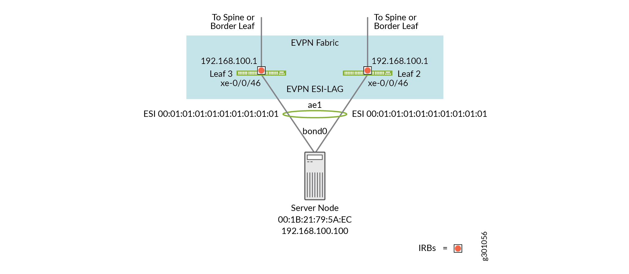
Figure 1 illustrates the topology for this EVPN Multihoming upgrade example. Note that both switches have an IRB interface configured for the VLAN associated with the attached host. These IRBs are configured with a shared virtual gateway address of 192.168.0.1. The host is assigned address 192.1689.1.100 on its bond0 interface. The diagram also details the MAC address of the bond0 interface on the host and the Ethernet segment identifier (ESI) that is configured on the LAG interface of both leaf switches.
EVPN Multihoming Upgrade Configuration
Prepare for the Upgrade
Step-by-Step Procedure
Verify that EVPN Multihoming is operational. Log into the server and confirm the bond interface is up. While there, make a note of the bond0 interface's MAC address. In this example the host is running Ubuntu so the
ifconfigcommand is used. If using a Centos distribution use theip link show bond0command. The MAC address for the host’s bond0 interface in this example is 00:1B:21:79:5A:EC.root@server-host# ifconfig bond0 bond0 Link encap:Ethernet HWaddr 00:1B:21:79:5A:EC inet addr:192.168.100.100 Bcast:192.168.100.255 Mask:255.255.255.0 inet6 addr: fe80::21b:21ff:fe79:5aec/64 Scope:Link UP BROADCAST RUNNING MASTER MULTICAST MTU:1500 Metric:1 RX packets:99980 errors:0 dropped:0 overruns:0 frame:0 TX packets:2997762 errors:0 dropped:0 overruns:0 carrier:0 collisions:0 txqueuelen:0 RX bytes:12393700 (11.8 MiB) TX bytes:371717722 (354.4 MiB)Confirm the LAG interface is operational on both leaf devices with a
show interfaces ae1command. In this example the LAG interface is ae1 on both the leaf devices. Be aware that the aggregated interface number is a local index that can vary between the two leaf devices. It’s not the interface name, but the configuration of matched ESI andsystem-idparameters that logically binds the LAG interface between the two leaves. Be sure to confirm that the LAG interface is up on both leaf devices.The output confirms that the LAG interface is operation an that the ESI is configured as 00:01:01:01:01:01:01:01:01:01 on both leaves.
root@leaf3> show interfaces ae1 Physical interface: ae1, Enabled, Physical link is Up Interface index: 640, SNMP ifIndex: 529 Link-level type: Ethernet, MTU: 1514, Speed: 10Gbps, BPDU Error: None, Ethernet-Switching Error: None, MAC-REWRITE Error: None, Loopback: Disabled, Source filtering: Disabled, Flow control: Disabled, Minimum links needed: 1, Minimum bandwidth needed: 1bps Device flags : Present Running Interface flags: SNMP-Traps Internal: 0x4000 Current address: 10:0e:7e:b5:7e:f0, Hardware address: 10:0e:7e:b5:7e:f0 Ethernet segment value: 00:01:01:01:01:01:01:01:01:01, Mode: all-active Last flapped : 2020-05-06 21:44:35 UTC (1d 09:25 ago) Input rate : 960 bps (0 pps) Output rate : 0 bps (0 pps) Logical interface ae1.0 (Index 550) (SNMP ifIndex 530) Flags: Up SNMP-Traps 0x24024000 Encapsulation: Ethernet-Bridge Statistics Packets pps Bytes bps Bundle: Input : 0 0 0 0 Output: 0 0 0 0 Adaptive Statistics: Adaptive Adjusts: 0 Adaptive Scans : 0 Adaptive Updates: 0 Protocol eth-switch, MTU: 1514 Flags: Is-Primaryroot@leaf2> show interfaces ae1 Physical interface: ae1, Enabled, Physical link is Up Interface index: 640, SNMP ifIndex: 541 Link-level type: Ethernet, MTU: 1514, Speed: 10Gbps, BPDU Error: None, Ethernet-Switching Error: None, MAC-REWRITE Error: None, Loopback: Disabled, Source filtering: Disabled, Flow control: Disabled, Minimum links needed: 1, Minimum bandwidth needed: 1bps Device flags : Present Running Interface flags: SNMP-Traps Internal: 0x4000 Current address: f4:b5:2f:44:af:30, Hardware address: f4:b5:2f:44:af:30 Ethernet segment value: 00:01:01:01:01:01:01:01:01:01, Mode: all-active Last flapped : 2020-05-08 05:58:07 UTC (01:22:18 ago) Input rate : 968 bps (0 pps) Output rate : 0 bps (0 pps) Logical interface ae1.0 (Index 554) (SNMP ifIndex 542) Flags: Up SNMP-Traps 0x24024000 Encapsulation: Ethernet-Bridge Statistics Packets pps Bytes bps Bundle: Input : 0 0 0 0 Output: 0 0 0 0 Adaptive Statistics: Adaptive Adjusts: 0 Adaptive Scans : 0 Adaptive Updates: 0 Protocol eth-switch, MTU: 1514 Flags: Is-PrimaryUse the ESI value noted in the previous step to confirm the host MAC address is present in the EVPN database of both member switches.
root@leaf3> show evpn database | match esi 00:01:01:01:01:01:01:01:01:01 Instance: default-switch VLAN DomainId MAC address Active source Timestamp IP address 10100 00:1b:21:79:5a:ec 00:01:01:01:01:01:01:01:01:01 May 08 08:23:11 192.168.100.100root@leaf3> show evpn database | match esi 00:01:01:01:01:01:01:01:01:01 Instance: default-switch VLAN DomainId MAC address Active source Timestamp IP address 10100 00:1b:21:79:5a:ec 00:01:01:01:01:01:01:01:01:01 May 07 22:06:11 192.168.100.100Display the aggregated interface configuration on both leaf devices. Note that the
hold-time upoption is configured for 6 seconds, in keeping with the recommendations in this example.root@leaf3> show configuration interfaces ae1 esi { 00:01:01:01:01:01:01:01:01:01; all-active; } aggregated-ether-options { lacp { active; system-id 00:00:01:01:01:01; hold-time up 6000; } } unit 0 { family ethernet-switching { interface-mode access; vlan { members v100; } } }root@leaf2> show configuration interfaces ae1 esi { 00:01:01:01:01:01:01:01:01:01; all-active; } aggregated-ether-options { lacp { active; system-id 00:00:01:01:01:01; hold-time up 6000; } } unit 0 { family ethernet-switching { interface-mode access; vlan { members v100; } } }Take note of the LAG member interface name on both switches. You will need to shut down this interface on the switch that is being upgraded. Its common for LAG member interface names to vary between a pair of switches. In this example the LAG member interface is xe-0/0/46 on both leaf devices.
root@leaf3> show lacp interfaces Aggregated interface: ae1 LACP state: Role Exp Def Dist Col Syn Aggr Timeout Activity xe-0/0/46 Actor No No Yes Yes Yes Yes Fast Active xe-0/0/46 Partner No No Yes Yes Yes Yes Slow Active LACP protocol: Receive State Transmit State Mux State xe-0/0/46 Current Slow periodic Collecting distributing . . .root@leaf2# run show lacp interfaces Aggregated interface: ae1 LACP state: Role Exp Def Dist Col Syn Aggr Timeout Activity xe-0/0/46 Actor No No Yes Yes Yes Yes Fast Active xe-0/0/46 Partner No No Yes Yes Yes Yes Slow Active LACP protocol: Receive State Transmit State Mux State xe-0/0/46 Current Slow periodic Collecting distributing . . .Transfer the desired Junos OS image to both leaf devices as shown in Figure 2. Be sure to place the image in the /var/tmp directory on the switches. Typically, either FTP or SCP is used to copy the image to the leaf devices. For details on using the CLI to copy files, see file copy.
Note:Consider running the
request system storage cleanupcommand before transferring the new image to ensure there is sufficient space for the upgrade.Figure 2: Transfer the New Junos Image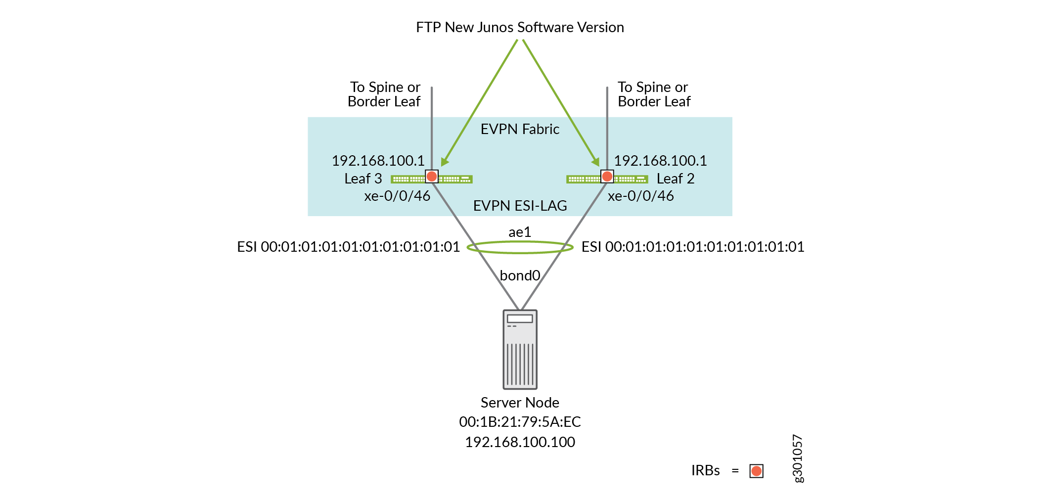
Confirm the starting Junos OS version on both the EVPN Multihoming leaves. In this example the starting Junos OS version is 19.1R3.9. For brevity only the output from leaf 2 is shown.
root@leaf2> show version
localre:
--------------------------------------------------------------------------
Hostname: leaf2
Model: qfx5100-48s-6q
Junos: 19.1R3.9
JUNOS OS Kernel 64-bit  [20200219.fb120e7_builder_stable_11]
JUNOS OS libs [20200219.fb120e7_builder_stable_11]
JUNOS OS runtime [20200219.fb120e7_builder_stable_11]
JUNOS OS time zone information [20200219.fb120e7_builder_stable_11]
JUNOS OS libs compat32 [20200219.fb120e7_builder_stable_11]
JUNOS OS 32-bit compatibility [20200219.fb120e7_builder_stable_11]
JUNOS py extensions [20200326.053318_builder_junos_191_r3]
. . .
The steps performed thus far indicate the LAG interfaces are operational and the EVPN control plane is converged. Before beginning the upgrade, start a ping from the host to the virtual gateway IP address assigned to the VLAN’s IRB interface. This traffic will hash to one member link or the other. It does not matter which switch the host sends the traffic to because both switches are configured with the same virtual gateway IP.
It’s important to note that either switch is able to reply to the ping. This means that when one switch is rebooting the other switch remains available and able to respond to the pings.
Note:In order for the pings to succeed you must make sure the IRB interface is configured with the
virtual-gateway-accept-dataoption on both switches.[root@serverhost ~]# ping 192.168.100.1 PING 192.168.100.1 (192.168.100.1) 56(84) bytes of data. 64 bytes from 192.168.100.1: icmp_seq=1 ttl=64 time=3.80 ms 64 bytes from 192.168.100.1: icmp_seq=2 ttl=64 time=1.93 ms 64 bytes from 192.168.100.1: icmp_seq=3 ttl=64 time=8.81 ms 64 bytes from 192.168.100.1: icmp_seq=4 ttl=64 time=2.91 ms 64 bytes from 192.168.100.1: icmp_seq=5 ttl=64 time=1.34 ms 64 bytes from 192.168.100.1: icmp_seq=6 ttl=64 time=15.0 ms ...
Be sure that the host to IRB interface pings remain running throughout the upgrade procedure so you can determine the total number of packets that are lost.
Upgrade leaf 3
Step-by-Step Procedure
Begin the upgrade process on Leaf 3 by shutting down the server facing LAG member xe-0/0/46, as shown in by the red “X” in Figure 3.
Note:A small number of packets in transit on the xe-0/0/46 interface of leaf 3 may be lost during this step. At this time the ping traffic flows through the leaf 2 device until the upgrade completes and you re-enable the downlink interface at leaf 3.
Figure 3: Disable the Downlink Interface on Leaf 3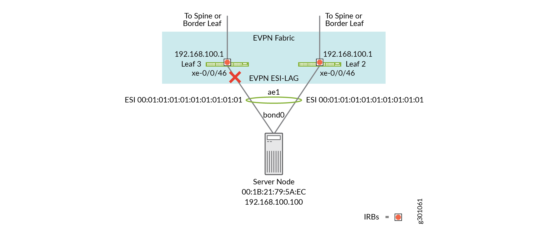
[edit interface xe-0/0/46]
root@leaf3# set disable
[edit interface xe-0/0/46]
root@leaf3# commit and-quit
Use a console connection to start the upgrade at leaf 3 using a
request system software add /var/tmp/jinstall-host-qfx-5e-x86-64-19.2R1.8-secure-signed.tgz
reboot
command. The image loading and subsequent reboot processes are represented by the gear icons in Figure 4. The upgrade process takes several minutes to complete. During this time your pings should be flowing through leaf 2, because it remains fully operational during the upgrade of leaf 3.Figure 4: Start the Upgrade of Leaf 3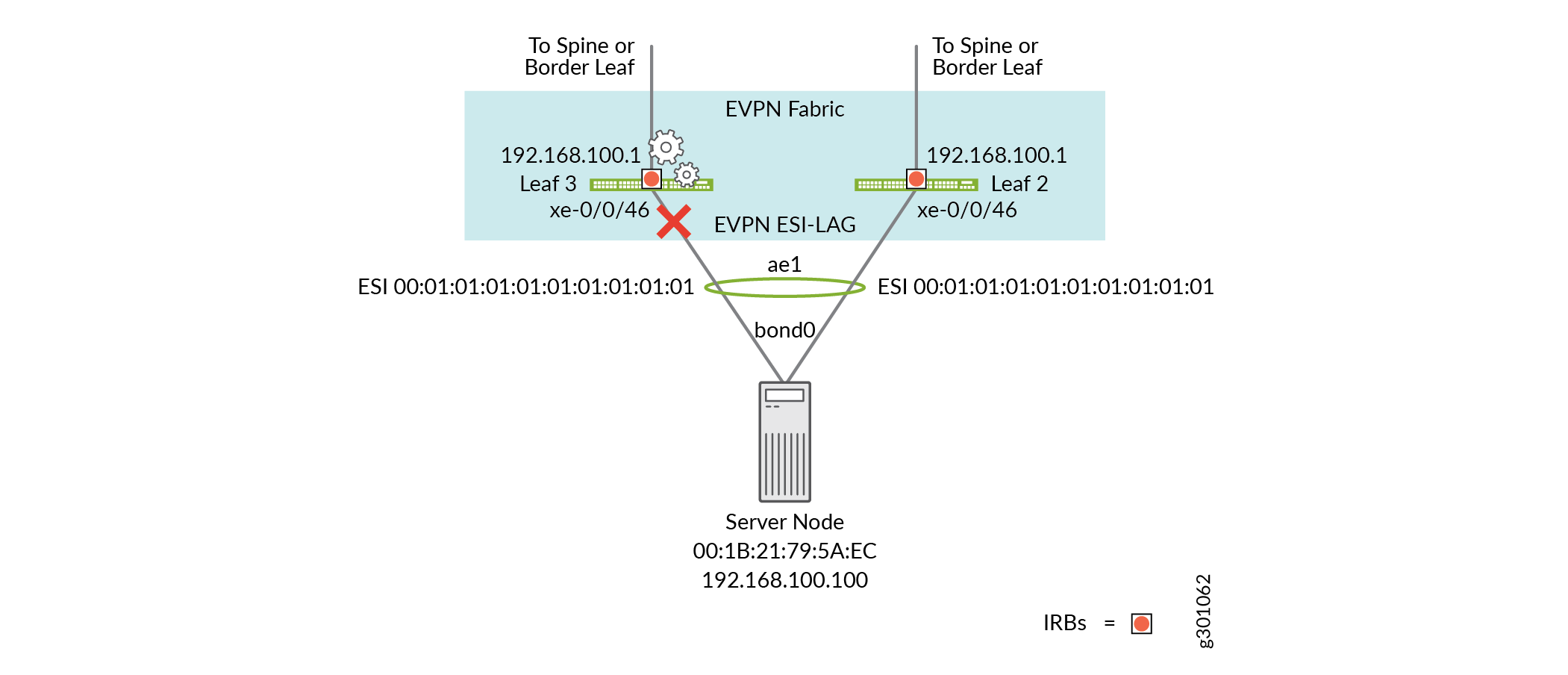
After the switch reboots confirm that the upgrade was successful.
root@leaf3> show version
localre:
--------------------------------------------------------------------------
Hostname: leaf3
Model: qfx5100-48s-6q
Junos: 19.2R1.8
JUNOS OS Kernel 64-bit  [20190517.f0321c3_builder_stable_11]
JUNOS OS libs [20190517.f0321c3_builder_stable_11]
JUNOS OS runtime [20190517.f0321c3_builder_stable_11]
JUNOS OS time zone information [20190517.f0321c3_builder_stable_11]
JUNOS OS libs compat32 [20190517.f0321c3_builder_stable_11]
JUNOS OS 32-bit compatibility [20190517.f0321c3_builder_stable_11]
JUNOS py extensions [20190621.152752_builder_junos_192_r1]
JUNOS py base [20190621.152752_builder_junos_192_r1]
JUNOS OS vmguest [20190517.f0321c3_builder_stable_11]
JUNOS OS crypto [20190517.f0321c3_builder_stable_11]
. . .
At this time all underlay and overlay BGP sessions should be reestablished. Confirm that all BGP peers are back up and that the EVPN control plane has reconverged before enabling the lag member interface at leaf 3.
root@leaf3> show evpn database esi 00:01:01:01:01:01:01:01:01:01
Instance: default-switch
VLAN  DomainId  MAC address        Active source                  Timestamp        IP address
     10100      00:1b:21:79:5a:ec  00:01:01:01:01:01:01:01:01:01  May 08 08:40:33  192.168.100.100
Enable the downlink interface on leaf 3, as shown by the green check mark in Figure 5.
Figure 5: Enable the Downlink Interface at Leaf 3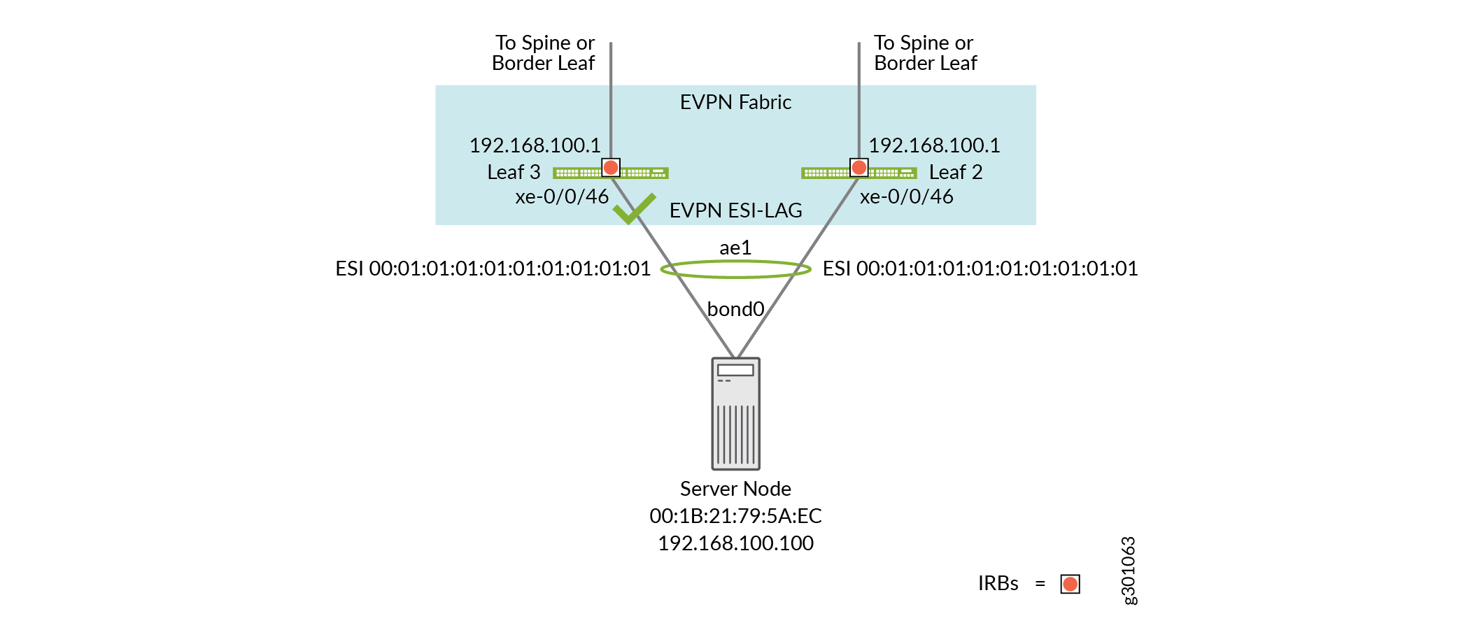
[edit interface xe-0/0/46]
root@leaf3# delete disable
[edit interface xe-0/0/46]
root@leaf3# commit and-quit
Upgrade leaf2
Step-by-Step Procedure
Begin the upgrade procedure on leaf 2 by disabling its downlink interface, as shown by the red X in Figure 6. Because the pings are likely flowing through leaf 2, this steps marks the second loss window in the procedure. The pings should continue to flow through the leaf 3 device as you upgrade leaf 2.
Figure 6: Disable the Downlink Interface on leaf2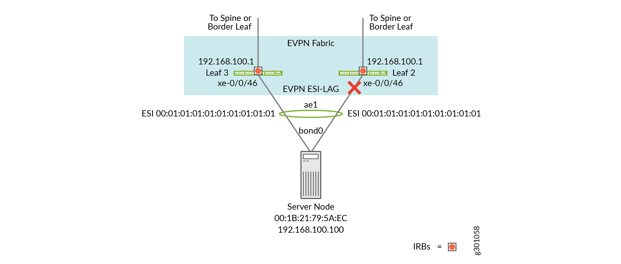
[edit interface xe-0/0/46]
root@leaf2# set disable
[edit interface xe-0/0/46]
root@leaf2# commit and-quit
Start the image load and reboot at leaf 2 with a
request system software add /var/tmp/jinstall-host-qfx-5e-x86-64-19.2R1.8-secure-signed.tgzcommand. The upgrade and reboot of leaf 2 is as shown with the gear icons in Figure 7.Figure 7: Start the Upgrade at Leaf 2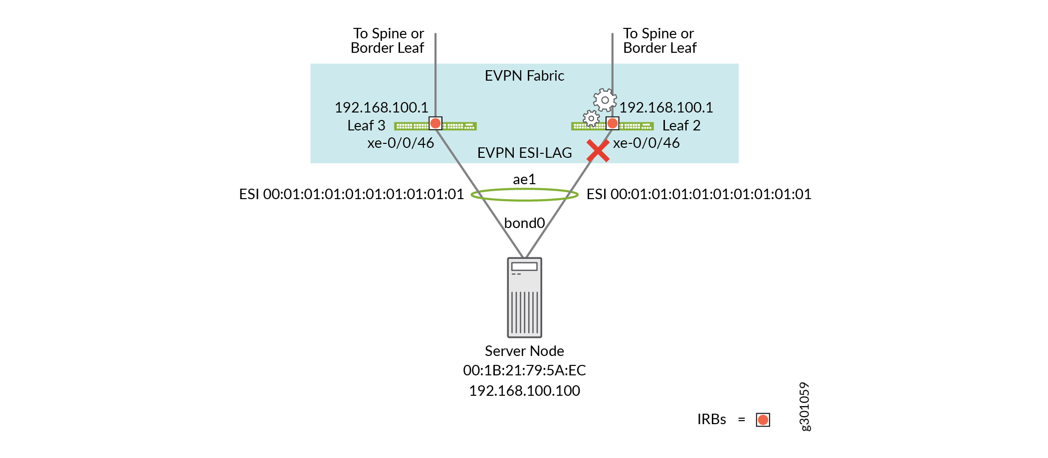
After leaf 2 reboots, check the Junos OS version to make sure that the upgrade was successful.
root@leaf2> show version
localre:
--------------------------------------------------------------------------
Hostname: leaf2
Model: qfx5100-48s-6q
Junos: 19.2R1.8
JUNOS OS Kernel 64-bit  [20190517.f0321c3_builder_stable_11]
JUNOS OS libs [20190517.f0321c3_builder_stable_11]
JUNOS OS runtime [20190517.f0321c3_builder_stable_11]
JUNOS OS time zone information [20190517.f0321c3_builder_stable_11]
JUNOS OS libs compat32 [20190517.f0321c3_builder_stable_11]
JUNOS OS 32-bit compatibility [20190517.f0321c3_builder_stable_11]
JUNOS py extensions [20190621.152752_builder_junos_192_r1]
JUNOS py base [20190621.152752_builder_junos_192_r1]
JUNOS OS vmguest [20190517.f0321c3_builder_stable_11]
JUNOS OS crypto [20190517.f0321c3_builder_stable_11]
. . .
Check that the EVPN control plane has reconverged at leaf 2. It may take a few minutes for all BGP session to reestablish and for the MAC address of the host to be populated in the EVPN database.
root@leaf2> show evpn database esi 00:01:01:01:01:01:01:01:01:01
Instance: default-switch
VLAN  DomainId  MAC address        Active source                  Timestamp        IP address
     10100      00:1b:21:79:5a:ec  00:01:01:01:01:01:01:01:01:01  May 08 08:53:30
Enable the LAG member interface on leaf 2 as shown by the green check mark in Figure 8.
Figure 8: Enable the Downlink Interface on leaf 2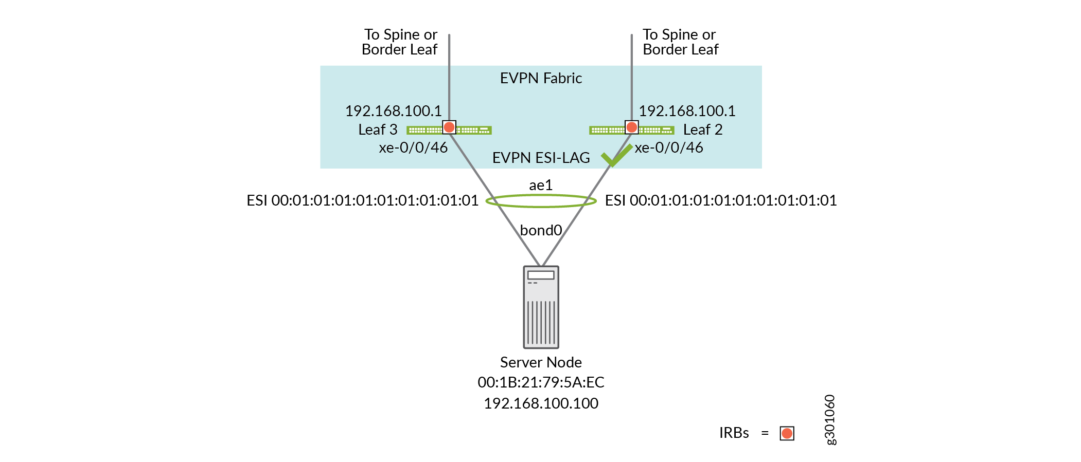
[edit interface xe-0/0/46]
root@leaf2# delete disable
[edit interface xe-0/0/46]
root@leaf2# commit and-quit
Both switches are now upgraded and all LAG member interfaces are again operational. To measure the traffic disruption during the upgrade process, stop the ping and note the ping statistics. In this example a total of two packets are lost during the upgrade of the pair of leaf devices that support the multihomed host.
In many cases the loss of a single packet is shown when an ongoing ping is disrupted. Regardless, whether it was 1 or 2 packets that are actually lost, the upgrade is deemed virtually hitless. This is in accordance with the expectations of the procedure demonstrated in this example.
[root@serverhost ~]# ping 192.168.100.1
...
64 bytes from 192.168.100.1: icmp_seq=1621 ttl=64 time=0.465 ms
64 bytes from 192.168.100.1: icmp_seq=1622 ttl=64 time=7.52 ms
64 bytes from 192.168.100.1: icmp_seq=1623 ttl=64 time=0.920 ms
64 bytes from 192.168.100.1: icmp_seq=1624 ttl=64 time=8.48 ms
64 bytes from 192.168.100.1: icmp_seq=1625 ttl=64 time=9.89 ms
64 bytes from 192.168.100.1: icmp_seq=1626 ttl=64 time=8.95 ms
64 bytes from 192.168.100.1: icmp_seq=1627 ttl=64 time=1.85 ms
^C
--- 192.168.100.1 ping statistics ---
1627 packets transmitted, 1625 received, 0% packet loss, time 1628654ms
rtt min/avg/max/mdev = 0.260/8.371/87.282/11.096 ms
Conclusion
EVPN Multihoming is an important feature for a datacenter architecture that must support both high-performance and high-availability. This example demonstrated the configuration and steps needed to upgrade a pair of leaf switches that support multihomed host attachments with minimal disruption.