Detailed Configurations for the EVPN-VXLAN Network for the Data Centers
This section includes the complete configurations for the following devices:
Data Center 1 Border Spine 1 and Border Spine 2 (DC1-Spine1 and DC1-Spine2)
Data Center 1 Leaf 1 and Leaf 2 (DC1-Leaf1 and DC1-Leaf2)
Data Center 2 Border Spine 1 and Border Spine 2 (DC2-Spine1 and DC1-Spine2)
Data Center 2 Leaf 1 and Leaf 2 (DC2-Leaf1 and DC2-Leaf2)
A simplified WAN router configuration that can be used for testing
Figure 1 shows the detailed topology used in this example.
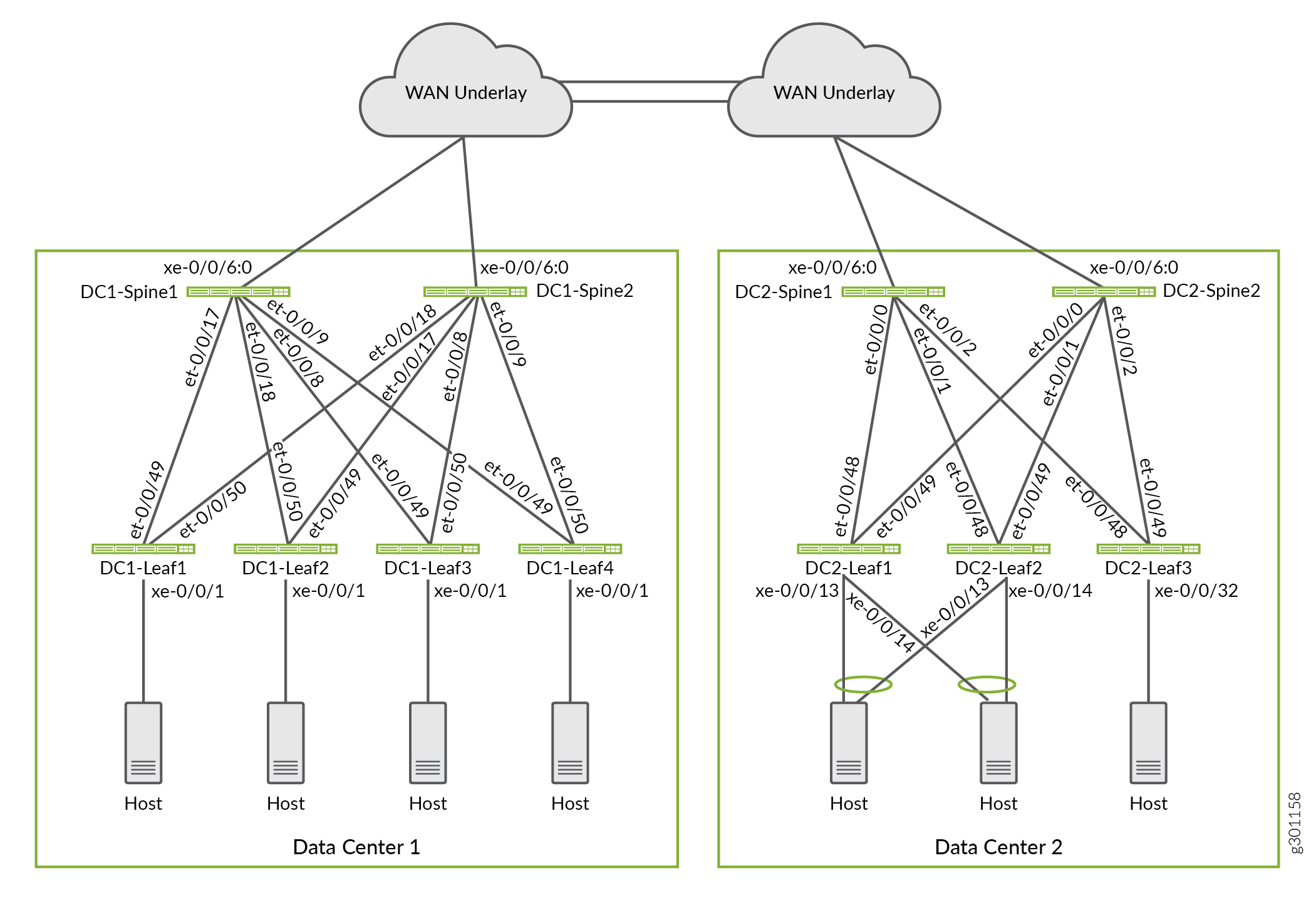
The configurations are shown as typed, rather than as
displayed with a show configuration | display set command.
As a result the BGP authentication key appears in plain text instead
of the obfuscated form. The authentication key used is for testing
purposes and should be changed to suit your environment.
The need to channelize for 10 GE interfaces varies by QFX switch model. Based on the equipment used in this example channelization is not needed at the leaf switches, but is used on the spines for the 10 GE links to the WAN cloud.
Border Spine Device 1 in Data Center 1
set chassis fpc 0 pic 0 port 6 channel-speed 10
set interfaces xe-0/0/6:0 mtu 9200
set interfaces xe-0/0/6:0 unit 0 family inet address 172.16.1.7/31
set interfaces et-0/0/8 description "Fabric link"
set interfaces et-0/0/8 mtu 9200
set interfaces et-0/0/8 unit 0 description "** to DC1-Leaf3"
set interfaces et-0/0/8 unit 0 family inet address 10.80.224.6/31
set interfaces et-0/0/9 description "Fabric link"
set interfaces et-0/0/9 mtu 9200
set interfaces et-0/0/9 unit 0 description "** to DC1-Leaf4"
set interfaces et-0/0/9 unit 0 family inet address 10.80.224.8/31
set interfaces et-0/0/17 description "Fabric link"
set interfaces et-0/0/17 mtu 9200
set interfaces et-0/0/17 unit 0 description "** to DC1-Leaf1"
set interfaces et-0/0/17 unit 0 family inet address 10.80.224.2/31
set interfaces et-0/0/18 description "Fabric link"
set interfaces et-0/0/18 traps
set interfaces et-0/0/18 mtu 9200
set interfaces et-0/0/18 unit 0 description "** to DC1-Leaf2"
set interfaces et-0/0/18 unit 0 family inet address 10.80.224.4/31
set interfaces lo0 unit 0 description "** DC1-Spine1"
set interfaces lo0 unit 0 family inet address 10.80.224.149/32
set policy-options policy-statement ECMP-POLICY then load-balance per-packet
set policy-options policy-statement FROM_Lo0 term 10 from interface lo0.0
set policy-options policy-statement FROM_Lo0 term 10 then accept
set policy-options policy-statement FROM_Lo0 term 20 then reject
set policy-options policy-statement UNDERLAY-EXPORT term LOOPBACK from route-filter 10.80.224.128/25 orlonger
set policy-options policy-statement UNDERLAY-EXPORT term LOOPBACK from route-filter 10.0.0.0/24 orlonger
set policy-options policy-statement UNDERLAY-EXPORT term LOOPBACK then accept
set policy-options policy-statement UNDERLAY-EXPORT term DEFAULT then reject
set policy-options policy-statement UNDERLAY-IMPORT term LOOPBACK from route-filter 10.80.224.128/25 orlonger
set policy-options policy-statement UNDERLAY-IMPORT term LOOPBACK from route-filter 10.0.0.0/24 orlonger
set policy-options policy-statement UNDERLAY-IMPORT term LOOPBACK then accept
set policy-options policy-statement UNDERLAY-IMPORT term DEFAULT then reject
set routing-options forwarding-table export ECMP-POLICY
set routing-options forwarding-table ecmp-fast-reroute
set routing-options autonomous-system 64730
set protocols bgp hold-time 10
set protocols bgp log-updown
set protocols bgp group EVPN_FABRIC type internal
set protocols bgp group EVPN_FABRIC bfd-liveness-detection minimum-interval 1000
set protocols bgp group EVPN_FABRIC bfd-liveness-detection multiplier 3
set protocols bgp group EVPN_FABRIC description "Reflector group for overlay IBGP peering with leaves"
set protocols bgp group EVPN_FABRIC local-address 10.80.224.149
set protocols bgp group EVPN_FABRIC family evpn signaling
set protocols bgp group EVPN_FABRIC authentication-key "samplepassword-fortesting"
set protocols bgp group EVPN_FABRIC vpn-apply-export
set protocols bgp group EVPN_FABRIC cluster 10.80.224.149
set protocols bgp group EVPN_FABRIC local-as 64730
set protocols bgp group EVPN_FABRIC multipath
set protocols bgp group EVPN_FABRIC neighbor 10.80.224.140
set protocols bgp group EVPN_FABRIC neighbor 10.80.224.141
set protocols bgp group EVPN_FABRIC neighbor 10.80.224.142
set protocols bgp group EVPN_FABRIC neighbor 10.80.224.143
set protocols bgp group UNDERLAY type external
set protocols bgp group UNDERLAY description "Group for underlay EBGP peering"
set protocols bgp group UNDERLAY import UNDERLAY-IMPORT
set protocols bgp group UNDERLAY family inet unicast
set protocols bgp group UNDERLAY authentication-key "samplepassword-fortesting"
set protocols bgp group UNDERLAY export UNDERLAY-EXPORT
set protocols bgp group UNDERLAY local-as 65001
set protocols bgp group UNDERLAY multipath multiple-as
set protocols bgp group UNDERLAY bfd-liveness-detection minimum-interval 350
set protocols bgp group UNDERLAY bfd-liveness-detection multiplier 3
set protocols bgp group UNDERLAY neighbor 10.80.224.3 peer-as 65012
set protocols bgp group UNDERLAY neighbor 10.80.224.5 peer-as 65013
set protocols bgp group UNDERLAY neighbor 10.80.224.7 peer-as 65014
set protocols bgp group UNDERLAY neighbor 10.80.224.9 peer-as 65015
set protocols bgp group UNDERLAY neighbor 172.16.1.6 peer-as 65199
set protocols bgp group OVERLAY_INTERDC type external
set protocols bgp group OVERLAY_INTERDC description "Group for overlay EBGP peering to remote DC"
set protocols bgp group OVERLAY_INTERDC multihop no-nexthop-change
set protocols bgp group OVERLAY_INTERDC local-address 10.80.224.149
set protocols bgp group OVERLAY_INTERDC family evpn signaling delay-route-advertisements minimum-delay routing-uptime 480
set protocols bgp group OVERLAY_INTERDC local-as 64730
set protocols bgp group OVERLAY_INTERDC multipath multiple-as
set protocols bgp group OVERLAY_INTERDC neighbor 10.0.0.2 peer-as 64830
set protocols bgp group OVERLAY_INTERDC neighbor 10.0.0.3 peer-as 64830
set protocols lldp interface all
Border Spine Device 2 in Data Center 1
set chassis fpc 0 pic 0 port 33 channel-speed 10g
set interfaces xe-0/0/6:0 mtu 9200
set interfaces xe-0/0/6:0 unit 0 family inet address 172.16.1.5/31
set interfaces et-0/0/8 description "Fabric link"
set interfaces et-0/0/8 mtu 9200
set interfaces et-0/0/8 unit 0 description "** to DC1-Leaf3"
set interfaces et-0/0/8 unit 0 family inet address 10.80.224.16/31
set interfaces et-0/0/9 description "Fabric link"
set interfaces et-0/0/9 mtu 9200
set interfaces et-0/0/9 unit 0 description "** to DC1-Leaf4"
set interfaces et-0/0/9 unit 0 family inet address 10.80.224.18/31
set interfaces et-0/0/17 description "Fabric link"
set interfaces et-0/0/17 mtu 9200
set interfaces et-0/0/17 unit 0 description "** to DC1-Leaf2"
set interfaces et-0/0/17 unit 0 family inet address 10.80.224.14/31
set interfaces et-0/0/18 description "Fabric link"
set interfaces et-0/0/18 mtu 9200
set interfaces et-0/0/18 unit 0 description "** to DC1-Leaf1"
set interfaces et-0/0/18 unit 0 family inet address 10.80.224.12/31
set interfaces lo0 unit 0 description "** DC1-Spine2"
set interfaces lo0 unit 0 family inet address 10.80.224.150/32
set policy-options policy-statement ECMP-POLICY then load-balance per-packet
set policy-options policy-statement FROM_Lo0 term 10 from interface lo0.0
set policy-options policy-statement FROM_Lo0 term 10 then accept
set policy-options policy-statement FROM_Lo0 term 20 then reject
set policy-options policy-statement UNDERLAY-EXPORT term LOOPBACK from route-filter 10.80.224.128/25 orlonger
set policy-options policy-statement UNDERLAY-EXPORT term LOOPBACK then accept
set policy-options policy-statement UNDERLAY-EXPORT term DEFAULT then reject
set policy-options policy-statement UNDERLAY-IMPORT term LOOPBACK from route-filter 10.80.224.128/25 orlonger
set policy-options policy-statement UNDERLAY-IMPORT term LOOPBACK from route-filter 10.0.0.0/24 orlonger
set policy-options policy-statement UNDERLAY-IMPORT term LOOPBACK then accept
set policy-options policy-statement UNDERLAY-IMPORT term DEFAULT then reject
set routing-options forwarding-table export ECMP-POLICY
set routing-options forwarding-table ecmp-fast-reroute
set routing-options autonomous-system 64730
set protocols bgp hold-time 10
set protocols bgp log-updown
set protocols bgp group EVPN_FABRIC type internal
set protocols bgp group EVPN_FABRIC bfd-liveness-detection minimum-interval 1000
set protocols bgp group EVPN_FABRIC bfd-liveness-detection multiplier 3
set protocols bgp group EVPN_FABRIC description "Reflector group for overlay IBGP peering with leaves"
set protocols bgp group EVPN_FABRIC local-address 10.80.224.150
set protocols bgp group EVPN_FABRIC family evpn signaling
set protocols bgp group EVPN_FABRIC authentication-key "samplepassword-fortesting"
set protocols bgp group EVPN_FABRIC vpn-apply-export
set protocols bgp group EVPN_FABRIC cluster 10.80.224.150
set protocols bgp group EVPN_FABRIC local-as 64730
set protocols bgp group EVPN_FABRIC multipath
set protocols bgp group EVPN_FABRIC neighbor 10.80.224.140
set protocols bgp group EVPN_FABRIC neighbor 10.80.224.141
set protocols bgp group EVPN_FABRIC neighbor 10.80.224.142
set protocols bgp group EVPN_FABRIC neighbor 10.80.224.143
set protocols bgp group UNDERLAY type external
set protocols bgp group UNDERLAY description "Group for underlay EBGP peering"
set protocols bgp group UNDERLAY import UNDERLAY-IMPORT
set protocols bgp group UNDERLAY family inet unicast
set protocols bgp group UNDERLAY authentication-key "samplepassword-fortesting"
set protocols bgp group UNDERLAY export UNDERLAY-EXPORT
set protocols bgp group UNDERLAY local-as 65002
set protocols bgp group UNDERLAY multipath multiple-as
set protocols bgp group UNDERLAY bfd-liveness-detection minimum-interval 350
set protocols bgp group UNDERLAY bfd-liveness-detection multiplier 3
set protocols bgp group UNDERLAY neighbor 10.80.224.13 peer-as 65012
set protocols bgp group UNDERLAY neighbor 10.80.224.19 peer-as 65015
set protocols bgp group UNDERLAY neighbor 10.80.224.17 peer-as 65014
set protocols bgp group UNDERLAY neighbor 10.80.224.15 peer-as 65013
set protocols bgp group UNDERLAY neighbor 172.16.1.4 peer-as 65199
set protocols bgp group OVERLAY_INTERDC type external
set protocols bgp group OVERLAY_INTERDC description "Group for overlay EBGP peering to remote DC"
set protocols bgp group OVERLAY_INTERDC multihop no-nexthop-change
set protocols bgp group OVERLAY_INTERDC local-address 10.80.224.150
set protocols bgp group OVERLAY_INTERDC family evpn signaling delay-route-advertisements minimum-delay routing-uptime 480
set protocols bgp group OVERLAY_INTERDC local-as 64730
set protocols bgp group OVERLAY_INTERDC multipath multiple-as
set protocols bgp group OVERLAY_INTERDC neighbor 10.0.0.2 peer-as 64830
set protocols bgp group OVERLAY_INTERDC neighbor 10.0.0.3 peer-as 64830
set protocols lldp interface all
Leaf Device 1 in Data Center 1
set system arp aging-timer 5
set interfaces xe-0/0/1 description "DC1 Server1"
set interfaces xe-0/0/1 unit 0 family ethernet-switching vlan members v203
set interfaces et-0/0/49 description "Fabric interface"
set interfaces et-0/0/49 mtu 9200
set interfaces et-0/0/49 unit 0 description "** to DC1-Spine1"
set interfaces et-0/0/49 unit 0 family inet address 10.80.224.3/31
set interfaces et-0/0/50 description "Fabric interface"
set interfaces et-0/0/50 mtu 9200
set interfaces et-0/0/50 unit 0 description "** to DC1-Spine2"
set interfaces et-0/0/50 unit 0 family inet address 10.80.224.13/31
set interfaces irb unit 10 virtual-gateway-accept-data
set interfaces irb unit 10 description "** L3 interface for v10 in Tenant_1"
set interfaces irb unit 10 family inet address 10.1.10.11/24 preferred
set interfaces irb unit 10 family inet address 10.1.10.11/24 virtual-gateway-address 10.1.10.1
set interfaces irb unit 11 virtual-gateway-accept-data
set interfaces irb unit 11 description "** L3 interface for v11 in Tenant_1"
set interfaces irb unit 11 family inet address 10.1.11.11/24 preferred
set interfaces irb unit 11 family inet address 10.1.11.11/24 virtual-gateway-address 10.1.11.1
set interfaces irb unit 12 virtual-gateway-accept-data
set interfaces irb unit 12 description "** L3 interface for v12 in Tenant_1"
set interfaces irb unit 12 family inet address 10.1.12.11/24 preferred
set interfaces irb unit 12 family inet address 10.1.12.11/24 virtual-gateway-address 10.1.12.1
set interfaces irb unit 202 virtual-gateway-accept-data
set interfaces irb unit 202 description "** L3 interface for v202 in Tenant_1"
set interfaces irb unit 202 family inet address 10.1.202.11/24 preferred
set interfaces irb unit 202 family inet address 10.1.202.11/24 virtual-gateway-address 10.1.202.1
set interfaces irb unit 203 virtual-gateway-accept-data
set interfaces irb unit 203 description "** L3 interface for v203 in Tenant_1"
set interfaces irb unit 203 family inet address 10.1.203.11/24 preferred
set interfaces irb unit 203 family inet address 10.1.203.11/24 virtual-gateway-address 10.1.203.1
set interfaces lo0 unit 0 description "** DC1-Leaf1"
set interfaces lo0 unit 0 family inet address 10.80.224.140/32
set interfaces lo0 unit 1 family inet address 10.80.225.140/32
set forwarding-options vxlan-routing overlay-ecmp
set forwarding-options vxlan-routing next-hop 32768
set policy-options policy-statement ECMP-POLICY then load-balance per-packet
set policy-options policy-statement FROM_Lo0 term 10 from interface lo0.0
set policy-options policy-statement FROM_Lo0 term 10 then accept
set policy-options policy-statement FROM_Lo0 term 20 then reject
set policy-options policy-statement OVERLAY_IMPORT term 5 from community comm_pod1
set policy-options policy-statement OVERLAY_IMPORT term 5 then accept
set policy-options policy-statement OVERLAY_IMPORT term 10 from community comm_pod2
set policy-options policy-statement OVERLAY_IMPORT term 10 then accept
set policy-options policy-statement OVERLAY_IMPORT term 20 from community shared_202_fm_pod2
set policy-options policy-statement OVERLAY_IMPORT term 20 from community shared_202_fm_pod1
set policy-options policy-statement OVERLAY_IMPORT term 20 from community shared_203_fm_pod2
set policy-options policy-statement OVERLAY_IMPORT term 20 from community shared_203_fm_pod1
set policy-options policy-statement OVERLAY_IMPORT term 20 then accept
set policy-options policy-statement T5_EXPORT term fm_direct from protocol direct
set policy-options policy-statement T5_EXPORT term fm_direct then accept
set policy-options policy-statement T5_EXPORT term fm_static from protocol static
set policy-options policy-statement T5_EXPORT term fm_static then accept
set policy-options policy-statement T5_EXPORT term fm_v4_host from protocol evpn
set policy-options policy-statement T5_EXPORT term fm_v4_host from route-filter 0.0.0.0/0 prefix-length-range /32-/32
set policy-options policy-statement T5_EXPORT term fm_v4_host then accept
set policy-options policy-statement T5_EXPORT term fm_v6_host from protocol evpn
set policy-options policy-statement T5_EXPORT term fm_v6_host from route-filter 0::0/0 prefix-length-range /128-/128
set policy-options policy-statement T5_EXPORT term fm_v6_host then accept
set policy-options policy-statement VRF1_T5_RT_EXPORT term t1 then community add target_t5_pod1
set policy-options policy-statement VRF1_T5_RT_EXPORT term t1 then accept
set policy-options policy-statement VRF1_T5_RT_IMPORT term t1 from community target_t5_pod1
set policy-options policy-statement VRF1_T5_RT_IMPORT term t1 then accept
set policy-options policy-statement VRF1_T5_RT_IMPORT term t2 from community target_t5_pod2
set policy-options policy-statement VRF1_T5_RT_IMPORT term t2 then accept
set policy-options community comm_pod1 members target:64730:999
set policy-options community comm_pod2 members target:64830:999
set policy-options community shared_202_fm_pod1 members target:64730:202
set policy-options community shared_202_fm_pod2 members target:64830:202
set policy-options community shared_203_fm_pod1 members target:64730:203
set policy-options community shared_203_fm_pod2 members target:64830:203
set policy-options community target_t5_pod1 members target:64730:9999
set policy-options community target_t5_pod2 members target:64830:9999
set routing-instances TENANT_1_VRF instance-type vrf
set routing-instances TENANT_1_VRF routing-options multipath
set routing-instances TENANT_1_VRF protocols evpn ip-prefix-routes advertise direct-nexthop
set routing-instances TENANT_1_VRF protocols evpn ip-prefix-routes encapsulation vxlan
set routing-instances TENANT_1_VRF protocols evpn ip-prefix-routes vni 9999
set routing-instances TENANT_1_VRF protocols evpn ip-prefix-routes export T5_EXPORT
set routing-instances TENANT_1_VRF routing-options multipath
set routing-instances TENANT_1_VRF description "VRF for Tenant_1"
set routing-instances TENANT_1_VRF interface irb.10
set routing-instances TENANT_1_VRF interface irb.11
set routing-instances TENANT_1_VRF interface irb.12
set routing-instances TENANT_1_VRF interface irb.202
set routing-instances TENANT_1_VRF interface irb.203
set routing-instances TENANT_1_VRF interface lo0.1
set routing-instances TENANT_1_VRF route-distinguisher 10.80.225.140:9999
set routing-instances TENANT_1_VRF vrf-import VRF1_T5_RT_IMPORT
set routing-instances TENANT_1_VRF vrf-export VRF1_T5_RT_EXPORT
set routing-instances TENANT_1_VRF vrf-target target:1:65001
set routing-instances TENANT_1_VRF vrf-table-label
set routing-options forwarding-table export ECMP-POLICY
set routing-options forwarding-table ecmp-fast-reroute
set routing-options forwarding-table chained-composite-next-hop ingress evpn
set routing-options router-id 10.80.224.140
set routing-options autonomous-system 64730
set protocols evpn vni-options vni 110 vrf-target target:64730:110
set protocols evpn vni-options vni 111 vrf-target target:64730:111
set protocols evpn vni-options vni 112 vrf-target target:64730:112
set protocols evpn vni-options vni 1202 vrf-target target:64730:202
set protocols evpn vni-options vni 1203 vrf-target target:64730:203
set protocols evpn encapsulation vxlan
set protocols evpn default-gateway no-gateway-community
set protocols evpn extended-vni-list 110
set protocols evpn extended-vni-list 111
set protocols evpn extended-vni-list 112
set protocols evpn extended-vni-list 1202
set protocols evpn extended-vni-list 1203
set protocols bgp group EVPN_FABRIC type internal
set protocols bgp group EVPN_FABRIC bfd-liveness-detection minimum-interval 1000
set protocols bgp group EVPN_FABRIC bfd-liveness-detection multiplier 3
set protocols bgp group EVPN_FABRIC description "Group for IBGP peering to reflectors"
set protocols bgp group EVPN_FABRIC local-address 10.80.224.140
set protocols bgp group EVPN_FABRIC family evpn signaling
set protocols bgp group EVPN_FABRIC authentication-key "samplepassword-fortesting"
set protocols bgp group EVPN_FABRIC local-as 64730
set protocols bgp group EVPN_FABRIC multipath
set protocols bgp group EVPN_FABRIC neighbor 10.80.224.149
set protocols bgp group EVPN_FABRIC neighbor 10.80.224.150
set protocols bgp group UNDERLAY type external
set protocols bgp group UNDERLAY description "Group for EBGP peering in underlay"
set protocols bgp group UNDERLAY family inet unicast
set protocols bgp group UNDERLAY authentication-key "samplepassword-fortesting"
set protocols bgp group UNDERLAY export FROM_Lo0
set protocols bgp group UNDERLAY local-as 65012
set protocols bgp group UNDERLAY multipath multiple-as
set protocols bgp group UNDERLAY bfd-liveness-detection minimum-interval 350
set protocols bgp group UNDERLAY bfd-liveness-detection multiplier 3
set protocols bgp group UNDERLAY neighbor 10.80.224.12 peer-as 65002
set protocols bgp group UNDERLAY neighbor 10.80.224.2 peer-as 65001
set protocols bgp hold-time 10
set protocols bgp log-updown
set protocols l2-learning global-mac-table-aging-time 600
set protocols l2-learning global-mac-ip-table-aging-time 300
set protocols lldp interface all
set switch-options vtep-source-interface lo0.0
set switch-options route-distinguisher 10.80.224.140:1
set switch-options vrf-import OVERLAY_IMPORT
set switch-options vrf-target target:64730:999
set vlans v10 description "Tenant_1 - VLAN id 10"
set vlans v10 vlan-id 10
set vlans v10 l3-interface irb.10
set vlans v10 vxlan vni 110
set vlans v11 description "Tenant_1 - VLAN id 11"
set vlans v11 vlan-id 11
set vlans v11 l3-interface irb.11
set vlans v11 vxlan vni 111
set vlans v12 description "Tenant_1 - VLAN id 12"
set vlans v12 vlan-id 12
set vlans v12 l3-interface irb.12
set vlans v12 vxlan vni 112
set vlans v202 description "Tenant_1 - VLAN id 202"
set vlans v202 vlan-id 202
set vlans v202 l3-interface irb.202
set vlans v202 vxlan vni 1202
set vlans v203 description "Tenant_1 - VLAN id 203"
set vlans v203 vlan-id 203
set vlans v203 l3-interface irb.203
set vlans v203 vxlan vni 1203
Leaf Device 2 in Data Center 1
set system arp aging-timer 5
set interfaces xe-0/0/1:0 description "DC1 Server2"
set interfaces xe-0/0/1:0 unit 0 family ethernet-switching vlan members v203
set interfaces et-0/0/49 description "Fabric interface"
set interfaces et-0/0/49 mtu 9200
set interfaces et-0/0/49 unit 0 description "** to DC1-Spine2"
set interfaces et-0/0/49 unit 0 family inet address 10.80.224.15/31
set interfaces et-0/0/50 description "Fabric interface"
set interfaces et-0/0/50 traps
set interfaces et-0/0/50 mtu 9200
set interfaces et-0/0/50 unit 0 description "** to DC1-Spine1"
set interfaces et-0/0/50 unit 0 family inet address 10.80.224.5/31
set interfaces irb unit 10 virtual-gateway-accept-data
set interfaces irb unit 10 description "** L3 interface for v10 in Tenant_1"
set interfaces irb unit 10 family inet address 10.1.10.12/24 preferred
set interfaces irb unit 10 family inet address 10.1.10.12/24 virtual-gateway-address 10.1.10.1
set interfaces irb unit 11 virtual-gateway-accept-data
set interfaces irb unit 11 description "** L3 interface for v11 in Tenant_1"
set interfaces irb unit 11 family inet address 10.1.11.12/24 preferred
set interfaces irb unit 11 family inet address 10.1.11.12/24 virtual-gateway-address 10.1.11.1
set interfaces irb unit 12 virtual-gateway-accept-data
set interfaces irb unit 12 description "** L3 interface for v12 in Tenant_1"
set interfaces irb unit 12 family inet address 10.1.12.12/24 preferred
set interfaces irb unit 12 family inet address 10.1.12.12/24 virtual-gateway-address 10.1.12.1
set interfaces irb unit 202 virtual-gateway-accept-data
set interfaces irb unit 202 description "** L3 interface for v202 in Tenant_1"
set interfaces irb unit 202 family inet address 10.1.202.12/24 preferred
set interfaces irb unit 202 family inet address 10.1.202.12/24 virtual-gateway-address 10.1.202.1
set interfaces irb unit 203 virtual-gateway-accept-data
set interfaces irb unit 203 description "** L3 interface for v203 in Tenant_1"
set interfaces irb unit 203 family inet address 10.1.203.12/24 preferred
set interfaces irb unit 203 family inet address 10.1.203.12/24 virtual-gateway-address 10.1.203.1
set interfaces lo0 unit 0 description "** DC1-Leaf2"
set interfaces lo0 unit 0 family inet address 10.80.224.141/32
set interfaces lo0 unit 1 family inet address 10.80.225.141/32
set forwarding-options vxlan-routing overlay-ecmp
set forwarding-options vxlan-routing next-hop 32768
set policy-options policy-statement ECMP-POLICY then load-balance per-packet
set policy-options policy-statement FROM_Lo0 term 10 from interface lo0.0
set policy-options policy-statement FROM_Lo0 term 10 then accept
set policy-options policy-statement FROM_Lo0 term 20 then reject
set policy-options policy-statement OVERLAY_IMPORT term 5 from community comm_pod1
set policy-options policy-statement OVERLAY_IMPORT term 5 then accept
set policy-options policy-statement OVERLAY_IMPORT term 10 from community comm_pod2
set policy-options policy-statement OVERLAY_IMPORT term 10 then accept
set policy-options policy-statement OVERLAY_IMPORT term 20 from community shared_202_fm_pod2
set policy-options policy-statement OVERLAY_IMPORT term 20 from community shared_202_fm_pod1
set policy-options policy-statement OVERLAY_IMPORT term 20 from community shared_203_fm_pod2
set policy-options policy-statement OVERLAY_IMPORT term 20 from community shared_203_fm_pod1
set policy-options policy-statement OVERLAY_IMPORT term 20 then accept
set policy-options policy-statement T5_EXPORT term fm_direct from protocol direct
set policy-options policy-statement T5_EXPORT term fm_direct then accept
set policy-options policy-statement T5_EXPORT term fm_static from protocol static
set policy-options policy-statement T5_EXPORT term fm_static then accept
set policy-options policy-statement T5_EXPORT term fm_v4_host from protocol evpn
set policy-options policy-statement T5_EXPORT term fm_v4_host from route-filter 0.0.0.0/0 prefix-length-range /32-/32
set policy-options policy-statement T5_EXPORT term fm_v4_host then accept
set policy-options policy-statement T5_EXPORT term fm_v6_host from protocol evpn
set policy-options policy-statement T5_EXPORT term fm_v6_host from route-filter 0::0/0 prefix-length-range /128-/128
set policy-options policy-statement T5_EXPORT term fm_v6_host then accept
set policy-options policy-statement VRF1_T5_RT_EXPORT term t1 then community add target_t5_pod1
set policy-options policy-statement VRF1_T5_RT_EXPORT term t1 then accept
set policy-options policy-statement VRF1_T5_RT_IMPORT term t1 from community target_t5_pod1
set policy-options policy-statement VRF1_T5_RT_IMPORT term t1 then accept
set policy-options policy-statement VRF1_T5_RT_IMPORT term t2 from community target_t5_pod2
set policy-options policy-statement VRF1_T5_RT_IMPORT term t2 then accept
set policy-options community comm_pod1 members target:64730:999
set policy-options community comm_pod2 members target:64830:999
set policy-options community shared_202_fm_pod1 members target:64730:202
set policy-options community shared_202_fm_pod2 members target:64830:202
set policy-options community shared_203_fm_pod1 members target:64730:203
set policy-options community shared_203_fm_pod2 members target:64830:203
set policy-options community target_t5_pod1 members target:64730:9999
set policy-options community target_t5_pod2 members target:64830:9999
set routing-instances TENANT_1_VRF instance-type vrf
set routing-instances TENANT_1_VRF protocols evpn ip-prefix-routes advertise direct-nexthop
set routing-instances TENANT_1_VRF protocols evpn ip-prefix-routes encapsulation vxlan
set routing-instances TENANT_1_VRF protocols evpn ip-prefix-routes vni 9999
set routing-instances TENANT_1_VRF protocols evpn ip-prefix-routes export T5_EXPORT
set routing-instances TENANT_1_VRF routing-options multipath
set routing-instances TENANT_1_VRF description "VRF for Tenant_1"
set routing-instances TENANT_1_VRF interface irb.10
set routing-instances TENANT_1_VRF interface irb.11
set routing-instances TENANT_1_VRF interface irb.12
set routing-instances TENANT_1_VRF interface irb.202
set routing-instances TENANT_1_VRF interface irb.203
set routing-instances TENANT_1_VRF interface lo0.1
set routing-instances TENANT_1_VRF route-distinguisher 10.80.225.141:9999
set routing-instances TENANT_1_VRF vrf-import VRF1_T5_RT_IMPORT
set routing-instances TENANT_1_VRF vrf-export VRF1_T5_RT_EXPORT
set routing-instances TENANT_1_VRF vrf-target target:1:65001
set routing-instances TENANT_1_VRF vrf-table-label
set routing-options forwarding-table export ECMP-POLICY
set routing-options forwarding-table ecmp-fast-reroute
set routing-options forwarding-table chained-composite-next-hop ingress evpn
set routing-options router-id 10.80.224.141
set routing-options autonomous-system 64730
set protocols evpn vni-options vni 110 vrf-target target:64730:110
set protocols evpn vni-options vni 111 vrf-target target:64730:111
set protocols evpn vni-options vni 112 vrf-target target:64730:112
set protocols evpn vni-options vni 1202 vrf-target target:64730:202
set protocols evpn vni-options vni 1203 vrf-target target:64730:203
set protocols evpn encapsulation vxlan
set protocols evpn default-gateway no-gateway-community
set protocols evpn extended-vni-list 110
set protocols evpn extended-vni-list 111
set protocols evpn extended-vni-list 112
set protocols evpn extended-vni-list 1202
set protocols evpn extended-vni-list 1203
set protocols bgp group EVPN_FABRIC type internal
set protocols bgp group EVPN_FABRIC bfd-liveness-detection minimum-interval 1000
set protocols bgp group EVPN_FABRIC bfd-liveness-detection multiplier 3
set protocols bgp group EVPN_FABRIC description "Group for IBGP peering to reflectors"
set protocols bgp group EVPN_FABRIC local-address 10.80.224.141
set protocols bgp group EVPN_FABRIC family evpn signaling
set protocols bgp group EVPN_FABRIC authentication-key "samplepassword-fortesting"
set protocols bgp group EVPN_FABRIC local-as 64730
set protocols bgp group EVPN_FABRIC multipath
set protocols bgp group EVPN_FABRIC neighbor 10.80.224.149
set protocols bgp group EVPN_FABRIC neighbor 10.80.224.150
set protocols bgp group UNDERLAY type external
set protocols bgp group UNDERLAY description "Group for EBGP peering in underlay"
set protocols bgp group UNDERLAY family inet unicast
set protocols bgp group UNDERLAY authentication-key "samplepassword-fortesting"
set protocols bgp group UNDERLAY export FROM_Lo0
set protocols bgp group UNDERLAY local-as 65013
set protocols bgp group UNDERLAY multipath multiple-as
set protocols bgp group UNDERLAY bfd-liveness-detection minimum-interval 350
set protocols bgp group UNDERLAY bfd-liveness-detection multiplier 3
set protocols bgp group UNDERLAY neighbor 10.80.224.4 peer-as 65001
set protocols bgp group UNDERLAY neighbor 10.80.224.14 peer-as 65002
set protocols bgp hold-time 10
set protocols bgp log-updown
set protocols l2-learning global-mac-table-aging-time 600
set protocols l2-learning global-mac-ip-table-aging-time 300
set protocols lldp interface all
set switch-options vtep-source-interface lo0.0
set switch-options route-distinguisher 10.80.224.141:1
set switch-options vrf-import OVERLAY_IMPORT
set switch-options vrf-target target:64730:999
set vlans v10 description "Tenant_1 - VLAN id 10"
set vlans v10 vlan-id 10
set vlans v10 l3-interface irb.10
set vlans v10 vxlan vni 110
set vlans v11 description "Tenant_1 - VLAN id 11"
set vlans v11 vlan-id 11
set vlans v11 l3-interface irb.11
set vlans v11 vxlan vni 111
set vlans v12 description "Tenant_1 - VLAN id 12"
set vlans v12 vlan-id 12
set vlans v12 l3-interface irb.12
set vlans v12 vxlan vni 112
set vlans v202 description "Tenant_1 - VLAN id 202"
set vlans v202 vlan-id 202
set vlans v202 l3-interface irb.202
set vlans v202 vxlan vni 1202
set vlans v203 description "Tenant_1 - VLAN id 203"
set vlans v203 vlan-id 203
set vlans v203 l3-interface irb.203
set vlans v203 vxlan vni 1203
Border Spine 1 in Data Center 2
set chassis fpc 0 pic 0 port 6 channel-speed 10g
set interfaces et-0/0/0 description "Fabric interface"
set interfaces et-0/0/0 mtu 9200
set interfaces et-0/0/0 unit 0 description "** to DC2-Leaf1"
set interfaces et-0/0/0 unit 0 family inet address 172.16.0.0/31
set interfaces et-0/0/1 description "Fabric interface"
set interfaces et-0/0/1 mtu 9200
set interfaces et-0/0/1 unit 0 description "** to DC2-Leaf2"
set interfaces et-0/0/1 unit 0 family inet address 172.16.0.2/31
set interfaces et-0/0/2 description "Fabric interface"
set interfaces et-0/0/2 mtu 9200
set interfaces et-0/0/2 unit 0 description "** to DC2-Leaf3"
set interfaces et-0/0/2 unit 0 family inet address 172.16.0.4/31
set interfaces xe-0/0/6:1 description "To WAN Router"
set interfaces xe-0/0/6:1 mtu 9200
set interfaces xe-0/0/6:1 unit 0 family inet address 172.16.1.9/31
set interfaces lo0 unit 0 description "** DC2-Spine1"
set interfaces lo0 unit 0 family inet address 10.0.0.2/32
set policy-options policy-statement ECMP-POLICY then load-balance per-packet
set policy-options policy-statement FROM_Lo0 term 10 from interface lo0.0
set policy-options policy-statement FROM_Lo0 term 10 then accept
set policy-options policy-statement FROM_Lo0 term 20 then reject
set policy-options policy-statement UNDERLAY-EXPORT term LOOPBACK from route-filter 10.80.224.128/25 orlonger
set policy-options policy-statement UNDERLAY-EXPORT term LOOPBACK from route-filter 10.0.0.0/24 orlonger
set policy-options policy-statement UNDERLAY-EXPORT term LOOPBACK then accept
set policy-options policy-statement UNDERLAY-EXPORT term DEFAULT then reject
set policy-options policy-statement UNDERLAY-IMPORT term LOOPBACK from route-filter 10.80.224.128/25 orlonger
set policy-options policy-statement UNDERLAY-IMPORT term LOOPBACK from route-filter 10.0.0.0/24 orlonger
set policy-options policy-statement UNDERLAY-IMPORT term LOOPBACK then accept
set policy-options policy-statement UNDERLAY-IMPORT term DEFAULT then reject
set routing-options forwarding-table export ECMP-POLICY
set routing-options forwarding-table ecmp-fast-reroute
set routing-options autonomous-system 64830
set routing-options forwarding-table chained-composite-next-hop ingress evpn
set protocols bgp group UNDERLAY type external
set protocols bgp group UNDERLAY description "Group for EBGP peering in underlay"
set protocols bgp group UNDERLAY import UNDERLAY-IMPORT
set protocols bgp group UNDERLAY family inet unicast
set protocols bgp group UNDERLAY authentication-key "samplepassword-fortesting"
set protocols bgp group UNDERLAY export UNDERLAY-EXPORT
set protocols bgp group UNDERLAY local-as 65101
set protocols bgp group UNDERLAY multipath multiple-as
set protocols bgp group UNDERLAY bfd-liveness-detection minimum-interval 350
set protocols bgp group UNDERLAY bfd-liveness-detection multiplier 3
set protocols bgp group UNDERLAY neighbor 172.16.0.3 peer-as 65018
set protocols bgp group UNDERLAY neighbor 172.16.0.1 peer-as 65019
set protocols bgp group UNDERLAY neighbor 172.16.0.5 peer-as 65020
set protocols bgp group UNDERLAY neighbor 172.16.1.8 peer-as 65229
set protocols bgp group EVPN_FABRIC type internal
set protocols bgp group EVPN_FABRIC description "Group for overlay IBGP peering to reflectors"
set protocols bgp group EVPN_FABRIC local-address 10.0.0.2
set protocols bgp group EVPN_FABRIC family evpn signaling
set protocols bgp group EVPN_FABRIC authentication-key "samplepassword-fortesting"
set protocols bgp group EVPN_FABRIC cluster 10.0.0.2
set protocols bgp group EVPN_FABRIC local-as 64830
set protocols bgp group EVPN_FABRIC multipath
set protocols bgp group EVPN_FABRIC bfd-liveness-detection minimum-interval 1000
set protocols bgp group EVPN_FABRIC bfd-liveness-detection multiplier 3
set protocols bgp group EVPN_FABRIC neighbor 10.0.0.19
set protocols bgp group EVPN_FABRIC neighbor 10.0.0.18
set protocols bgp group EVPN_FABRIC neighbor 10.0.0.14
set protocols bgp group EVPN_FABRIC vpn-apply-export
set protocols bgp group OVERLAY_INTERDC type external
set protocols bgp group OVERLAY_INTERDC description "Group for overlay EBGP peering to remote DC"
set protocols bgp group OVERLAY_INTERDC multihop no-nexthop-change
set protocols bgp group OVERLAY_INTERDC local-address 10.0.0.2
set protocols bgp group OVERLAY_INTERDC family evpn signaling delay-route-advertisements minimum-delay routing-uptime 480
set protocols bgp group OVERLAY_INTERDC local-as 64830
set protocols bgp group OVERLAY_INTERDC multipath multiple-as
set protocols bgp group OVERLAY_INTERDC neighbor 10.80.224.149 peer-as 64730
set protocols bgp group OVERLAY_INTERDC neighbor 10.80.224.150 peer-as 64730
set protocols bgp hold-time 10
set protocols bgp log-updown
set protocols lldp interface all
Border Spine Device 2 in Data Center 2
set chassis fpc 0 pic 0 port 6 channel-speed 10g
set interfaces et-0/0/0 description "Fabric interface"
set interfaces et-0/0/0 mtu 9200
set interfaces et-0/0/0 unit 0 description "** to DC2-Leaf1"
set interfaces et-0/0/0 unit 0 family inet address 172.16.0.6/31
set interfaces et-0/0/1 description "Fabric interface"
set interfaces et-0/0/1 mtu 9200
set interfaces et-0/0/1 unit 0 description "** to DC2-Leaf2"
set interfaces et-0/0/1 unit 0 family inet address 172.16.0.8/31
set interfaces et-0/0/2 description "Fabric interface"
set interfaces et-0/0/2 mtu 9200
set interfaces et-0/0/2 unit 0 description "** to DC2-Leaf3"
set interfaces et-0/0/2 unit 0 family inet address 172.16.0.10/31
set interfaces xe-0/0/6:1 description "To WAN Router"
set interfaces xe-0/0/6:1 mtu 9200
set interfaces xe-0/0/6:1 unit 0 family inet address 172.16.1.11/31
set interfaces lo0 unit 0 description "** DC2-Spine2"
set interfaces lo0 unit 0 family inet address 10.0.0.3/32
set forwarding-options vxlan-routing overlay-ecmp
set policy-options policy-statement ECMP-POLICY then load-balance per-packet
set policy-options policy-statement FROM_Lo0 term 10 from interface lo0.0
set policy-options policy-statement FROM_Lo0 term 10 then accept
set policy-options policy-statement FROM_Lo0 term 20 then reject
set policy-options policy-statement UNDERLAY-EXPORT term LOOPBACK from route-filter 10.80.224.128/25 orlonger
set policy-options policy-statement UNDERLAY-EXPORT term LOOPBACK from route-filter 10.0.0.0/24 orlonger
set policy-options policy-statement UNDERLAY-EXPORT term LOOPBACK then accept
set policy-options policy-statement UNDERLAY-EXPORT term DEFAULT then reject
set policy-options policy-statement UNDERLAY-IMPORT term LOOPBACK from route-filter 10.80.224.128/25 orlonger
set policy-options policy-statement UNDERLAY-IMPORT term LOOPBACK from route-filter 10.0.0.0/24 orlonger
set policy-options policy-statement UNDERLAY-IMPORT term LOOPBACK then accept
set policy-options policy-statement UNDERLAY-IMPORT term DEFAULT then reject
set routing-options forwarding-table export ECMP-POLICY
set routing-options forwarding-table ecmp-fast-reroute
set routing-options forwarding-table chained-composite-next-hop ingress evpn
set routing-options autonomous-system 64830
set protocols bgp group UNDERLAY type external
set protocols bgp group UNDERLAY description "Group for EBGP peering in underlay"
set protocols bgp group UNDERLAY import UNDERLAY-IMPORT
set protocols bgp group UNDERLAY family inet unicast
set protocols bgp group UNDERLAY authentication-key "samplepassword-fortesting"
set protocols bgp group UNDERLAY export UNDERLAY-EXPORT
set protocols bgp group UNDERLAY local-as 65102
set protocols bgp group UNDERLAY multipath multiple-as
set protocols bgp group UNDERLAY bfd-liveness-detection minimum-interval 350
set protocols bgp group UNDERLAY bfd-liveness-detection multiplier 3
set protocols bgp group UNDERLAY neighbor 172.16.0.9 peer-as 65018
set protocols bgp group UNDERLAY neighbor 172.16.0.7 peer-as 65019
set protocols bgp group UNDERLAY neighbor 172.16.0.11 peer-as 65020
set protocols bgp group UNDERLAY neighbor 172.16.1.10 peer-as 65229
set protocols bgp group EVPN_FABRIC type internal
set protocols bgp group EVPN_FABRIC description "Group for overlay IBGP peering to reflectors"
set protocols bgp group EVPN_FABRIC local-address 10.0.0.3
set protocols bgp group EVPN_FABRIC family evpn signaling
set protocols bgp group EVPN_FABRIC authentication-key "samplepassword-fortesting"
set protocols bgp group EVPN_FABRIC cluster 10.0.0.3
set protocols bgp group EVPN_FABRIC local-as 64830
set protocols bgp group EVPN_FABRIC multipath
set protocols bgp group EVPN_FABRIC bfd-liveness-detection minimum-interval 1000
set protocols bgp group EVPN_FABRIC bfd-liveness-detection multiplier 3
set protocols bgp group EVPN_FABRIC neighbor 10.0.0.19
set protocols bgp group EVPN_FABRIC neighbor 10.0.0.18
set protocols bgp group EVPN_FABRIC neighbor 10.0.0.14
set protocols bgp group EVPN_FABRIC vpn-apply-export
set protocols bgp group OVERLAY_INTERDC type external
set protocols bgp group OVERLAY_INTERDC description "Group for overlay EBGP peering to remote DC"
set protocols bgp group OVERLAY_INTERDC multihop no-nexthop-change
set protocols bgp group OVERLAY_INTERDC local-address 10.0.0.3
set protocols bgp group OVERLAY_INTERDC family evpn signaling delay-route-advertisements minimum-delay routing-uptime 480
set protocols bgp group OVERLAY_INTERDC local-as 64830
set protocols bgp group OVERLAY_INTERDC multipath multiple-as
set protocols bgp group OVERLAY_INTERDC neighbor 10.80.224.149 peer-as 64730
set protocols bgp group OVERLAY_INTERDC neighbor 10.80.224.150 peer-as 64730
set protocols bgp hold-time 10
set protocols bgp log-updown
set protocols lldp interface all
Leaf Device 1 in Data Center 2
set system arp aging-timer 5
set chassis aggregated-devices ethernet device-count 20
set interfaces xe-0/0/13 ether-options 802.3ad ae1
set interfaces xe-0/0/14 ether-options 802.3ad ae2
set interfaces et-0/0/48 description "Fabric interface"
set interfaces et-0/0/48 mtu 9200
set interfaces et-0/0/48 unit 0 description "** to DC2-Spine1"
set interfaces et-0/0/48 unit 0 family inet address 172.16.0.1/31
set interfaces et-0/0/49 description "Fabric interface"
set interfaces et-0/0/49 mtu 9200
set interfaces et-0/0/49 unit 0 description "** to DC2-Spine2"
set interfaces et-0/0/49 unit 0 family inet address 172.16.0.7/31
set interfaces ae1 description "DC2 Server1"
set interfaces ae1 esi 00:00:00:00:00:02:02:02:02:01
set interfaces ae1 esi all-active
set interfaces ae1 aggregated-ether-options link-speed 10g
set interfaces ae1 aggregated-ether-options lacp active
set interfaces ae1 aggregated-ether-options lacp periodic fast
set interfaces ae1 aggregated-ether-options lacp system-id 00:02:02:02:02:01
set interfaces ae1 unit 0 family ethernet-switching interface-mode trunk
set interfaces ae1 unit 0 family ethernet-switching vlan members v170
set interfaces ae1 unit 0 family ethernet-switching vlan members v171
set interfaces ae1 unit 0 family ethernet-switching vlan members v172
set interfaces ae1 unit 0 family ethernet-switching vlan members v202
set interfaces ae1 unit 0 family ethernet-switching vlan members v203
set interfaces ae2 description "DC2 Server2"
set interfaces ae2 esi 00:00:00:00:00:02:02:02:02:02
set interfaces ae2 esi all-active
set interfaces ae2 aggregated-ether-options link-speed 10g
set interfaces ae2 aggregated-ether-options lacp active
set interfaces ae2 aggregated-ether-options lacp periodic fast
set interfaces ae2 aggregated-ether-options lacp system-id 00:02:02:02:02:02
set interfaces ae2 unit 0 family ethernet-switching interface-mode trunk
set interfaces ae2 unit 0 family ethernet-switching vlan members v170
set interfaces ae2 unit 0 family ethernet-switching vlan members v171
set interfaces ae2 unit 0 family ethernet-switching vlan members v172
set interfaces ae2 unit 0 family ethernet-switching vlan members v202
set interfaces ae2 unit 0 family ethernet-switching vlan members v203
set interfaces irb unit 170 virtual-gateway-accept-data
set interfaces irb unit 170 description "** L3 interface for v170 in Tenant_1"
set interfaces irb unit 170 family inet address 10.1.170.19/24 preferred
set interfaces irb unit 170 family inet address 10.1.170.19/24 virtual-gateway-address 10.1.170.1
set interfaces irb unit 171 virtual-gateway-accept-data
set interfaces irb unit 171 description "** L3 interface for v171 in Tenant_1"
set interfaces irb unit 171 family inet address 10.1.171.19/24 preferred
set interfaces irb unit 171 family inet address 10.1.171.19/24 virtual-gateway-address 10.1.171.1
set interfaces irb unit 172 virtual-gateway-accept-data
set interfaces irb unit 172 description "** L3 interface for v172 in Tenant_1"
set interfaces irb unit 172 family inet address 10.1.172.19/24 preferred
set interfaces irb unit 172 family inet address 10.1.172.19/24 virtual-gateway-address 10.1.172.1
set interfaces irb unit 202 virtual-gateway-accept-data
set interfaces irb unit 202 description "** L3 interface for v202 in Tenant_1"
set interfaces irb unit 202 family inet address 10.1.202.19/24 preferred
set interfaces irb unit 202 family inet address 10.1.202.19/24 virtual-gateway-address 10.1.202.1
set interfaces irb unit 203 virtual-gateway-accept-data
set interfaces irb unit 203 description "** L3 interface for v203 in Tenant_1"
set interfaces irb unit 203 family inet address 10.1.203.19/24 preferred
set interfaces irb unit 203 family inet address 10.1.203.19/24 virtual-gateway-address 10.1.203.1
set interfaces lo0 traps
set interfaces lo0 unit 0 description "** DC2-Leaf1"
set interfaces lo0 unit 0 family inet address 10.0.0.19/32
set interfaces lo0 unit 1 family inet address 10.0.1.19/32
set forwarding-options vxlan-routing overlay-ecmp
set forwarding-options vxlan-routing next-hop 32768
set policy-options policy-statement ECMP-POLICY then load-balance per-packet
set policy-options policy-statement FROM_Lo0 term 10 from interface lo0.0
set policy-options policy-statement FROM_Lo0 term 10 then accept
set policy-options policy-statement FROM_Lo0 term 20 then reject
set policy-options policy-statement OVERLAY_IMPORT term 5 from community comm_pod1
set policy-options policy-statement OVERLAY_IMPORT term 5 then accept
set policy-options policy-statement OVERLAY_IMPORT term 10 from community comm_pod2
set policy-options policy-statement OVERLAY_IMPORT term 10 then accept
set policy-options policy-statement OVERLAY_IMPORT term 20 from community shared_202_fm_pod2
set policy-options policy-statement OVERLAY_IMPORT term 20 from community shared_202_fm_pod1
set policy-options policy-statement OVERLAY_IMPORT term 20 from community shared_203_fm_pod2
set policy-options policy-statement OVERLAY_IMPORT term 20 from community shared_203_fm_pod1
set policy-options policy-statement OVERLAY_IMPORT term 20 then accept
set policy-options policy-statement T5_EXPORT term fm_direct from protocol direct
set policy-options policy-statement T5_EXPORT term fm_direct then accept
set policy-options policy-statement T5_EXPORT term fm_static from protocol static
set policy-options policy-statement T5_EXPORT term fm_static then accept
set policy-options policy-statement T5_EXPORT term fm_v4_host from protocol evpn
set policy-options policy-statement T5_EXPORT term fm_v4_host from route-filter 0.0.0.0/0 prefix-length-range /32-/32
set policy-options policy-statement T5_EXPORT term fm_v4_host then accept
set policy-options policy-statement T5_EXPORT term fm_v6_host from protocol evpn
set policy-options policy-statement T5_EXPORT term fm_v6_host from route-filter 0::0/0 prefix-length-range /128-/128
set policy-options policy-statement T5_EXPORT term fm_v6_host then accept
set policy-options policy-statement VRF1_T5_RT_EXPORT term t1 then community add target_t5_pod2
set policy-options policy-statement VRF1_T5_RT_EXPORT term t1 then accept
set policy-options policy-statement VRF1_T5_RT_IMPORT term t1 from community target_t5_pod1
set policy-options policy-statement VRF1_T5_RT_IMPORT term t1 then accept
set policy-options policy-statement VRF1_T5_RT_IMPORT term t2 from community target_t5_pod2
set policy-options policy-statement VRF1_T5_RT_IMPORT term t2 then accept
set policy-options community comm_pod1 members target:64730:999
set policy-options community comm_pod2 members target:64830:999
set policy-options community shared_202_fm_pod1 members target:64730:202
set policy-options community shared_202_fm_pod2 members target:64830:202
set policy-options community shared_203_fm_pod1 members target:64730:203
set policy-options community shared_203_fm_pod2 members target:64830:203
set policy-options community target_t5_pod1 members target:64730:9999
set policy-options community target_t5_pod2 members target:64830:9999
set routing-instances TENANT_1_VRF description "VRF for Tenant_1"
set routing-instances TENANT_1_VRF instance-type vrf
set routing-instances TENANT_1_VRF interface irb.170
set routing-instances TENANT_1_VRF interface irb.171
set routing-instances TENANT_1_VRF interface irb.172
set routing-instances TENANT_1_VRF interface irb.202
set routing-instances TENANT_1_VRF interface irb.203
set routing-instances TENANT_1_VRF interface lo0.1
set routing-instances TENANT_1_VRF route-distinguisher 10.0.1.19:9999
set routing-instances TENANT_1_VRF vrf-import VRF1_T5_RT_IMPORT
set routing-instances TENANT_1_VRF vrf-export VRF1_T5_RT_EXPORT
set routing-instances TENANT_1_VRF vrf-target target:1:65001
set routing-instances TENANT_1_VRF vrf-table-label
set routing-instances TENANT_1_VRF routing-options multipath
set routing-instances TENANT_1_VRF protocols evpn ip-prefix-routes advertise direct-nexthop
set routing-instances TENANT_1_VRF protocols evpn ip-prefix-routes encapsulation vxlan
set routing-instances TENANT_1_VRF protocols evpn ip-prefix-routes vni 9999
set routing-instances TENANT_1_VRF protocols evpn ip-prefix-routes export T5_EXPORT
set routing-options router-id 10.0.0.19
set routing-options autonomous-system 64830
set routing-options forwarding-table export ECMP-POLICY
set routing-options forwarding-table ecmp-fast-reroute
set routing-options forwarding-table chained-composite-next-hop ingress evpn
set protocols bgp hold-time 10
set protocols bgp log-updown
set protocols bgp group EVPN_FABRIC type internal
set protocols bgp group EVPN_FABRIC bfd-liveness-detection minimum-interval 1000
set protocols bgp group EVPN_FABRIC bfd-liveness-detection multiplier 3
set protocols bgp group EVPN_FABRIC description "Group for overlay IBGP peering to reflectors"
set protocols bgp group EVPN_FABRIC local-address 10.0.0.19
set protocols bgp group EVPN_FABRIC family evpn signaling
set protocols bgp group EVPN_FABRIC authentication-key "samplepassword-fortesting"
set protocols bgp group EVPN_FABRIC local-as 64830
set protocols bgp group EVPN_FABRIC multipath
set protocols bgp group EVPN_FABRIC neighbor 10.0.0.2
set protocols bgp group EVPN_FABRIC neighbor 10.0.0.3
set protocols bgp group UNDERLAY type external
set protocols bgp group UNDERLAY description "Group for EBGP peering in underlay"
set protocols bgp group UNDERLAY family inet unicast
set protocols bgp group UNDERLAY authentication-key "samplepassword-fortesting"
set protocols bgp group UNDERLAY export FROM_Lo0
set protocols bgp group UNDERLAY local-as 65019
set protocols bgp group UNDERLAY multipath multiple-as
set protocols bgp group UNDERLAY bfd-liveness-detection minimum-interval 350
set protocols bgp group UNDERLAY bfd-liveness-detection multiplier 3
set protocols bgp group UNDERLAY neighbor 172.16.0.0 peer-as 65101
set protocols bgp group UNDERLAY neighbor 172.16.0.6 peer-as 65102
set protocols evpn vni-options vni 1170 vrf-target target:64830:1170
set protocols evpn vni-options vni 1171 vrf-target target:64830:1171
set protocols evpn vni-options vni 1172 vrf-target target:64830:1172
set protocols evpn vni-options vni 1202 vrf-target target:64830:202
set protocols evpn vni-options vni 1203 vrf-target target:64830:203
set protocols evpn encapsulation vxlan
set protocols evpn default-gateway no-gateway-community
set protocols evpn extended-vni-list 1170
set protocols evpn extended-vni-list 1171
set protocols evpn extended-vni-list 1172
set protocols evpn extended-vni-list 1202
set protocols evpn extended-vni-list 1203
set protocols l2-learning global-mac-table-aging-time 600
set protocols l2-learning global-mac-ip-table-aging-time 300
set protocols lldp interface all
set switch-options vtep-source-interface lo0.0
set switch-options route-distinguisher 10.0.0.19:1
set switch-options vrf-import OVERLAY_IMPORT
set switch-options vrf-target target:64830:999
set vlans v170 description "Tenant_1 - VLAN id 170"
set vlans v170 vlan-id 170
set vlans v170 l3-interface irb.170
set vlans v170 vxlan vni 1170
set vlans v171 description "Tenant_1 - VLAN id 171"
set vlans v171 vlan-id 171
set vlans v171 l3-interface irb.171
set vlans v171 vxlan vni 1171
set vlans v172 description "Tenant_1 - VLAN id 172"
set vlans v172 vlan-id 172
set vlans v172 l3-interface irb.172
set vlans v172 vxlan vni 1172
set vlans v202 description "Tenant_1 - VLAN id 202"
set vlans v202 vlan-id 202
set vlans v202 l3-interface irb.202
set vlans v202 vxlan vni 1202
set vlans v203 description "Tenant_1 - VLAN id 203"
set vlans v203 vlan-id 203
set vlans v203 l3-interface irb.203
set vlans v203 vxlan vni 1203
Leaf Device 2 in Data Center 2
set system arp aging-timer 5
set chassis aggregated-devices ethernet device-count 20
set interfaces xe-0/0/13 ether-options 802.3ad ae1
set interfaces xe-0/0/14 ether-options 802.3ad ae2
set interfaces et-0/0/48 description "Fabric interface"
set interfaces et-0/0/48 mtu 9200
set interfaces et-0/0/48 unit 0 description "** to DC2-Spine1"
set interfaces et-0/0/48 unit 0 family inet address 172.16.0.3/31
set interfaces et-0/0/49 description "Fabric interface"
set interfaces et-0/0/49 mtu 9200
set interfaces et-0/0/49 unit 0 description "** to DC2-Spine2"
set interfaces et-0/0/49 unit 0 family inet address 172.16.0.9/31
set interfaces ae1 description "DC2 Server1"
set interfaces ae1 mtu 9200
set interfaces ae1 esi 00:00:00:00:00:02:02:02:02:01
set interfaces ae1 esi all-active
set interfaces ae1 aggregated-ether-options link-speed 10g
set interfaces ae1 aggregated-ether-options lacp active
set interfaces ae1 aggregated-ether-options lacp periodic fast
set interfaces ae1 aggregated-ether-options lacp system-id 00:02:02:02:02:01
set interfaces ae1 unit 0 family ethernet-switching interface-mode trunk
set interfaces ae1 unit 0 family ethernet-switching vlan members v170
set interfaces ae1 unit 0 family ethernet-switching vlan members v171
set interfaces ae1 unit 0 family ethernet-switching vlan members v172
set interfaces ae1 unit 0 family ethernet-switching vlan members v202
set interfaces ae1 unit 0 family ethernet-switching vlan members v203
set interfaces ae2 description "DC2 Server2"
set interfaces ae2 mtu 9200
set interfaces ae2 esi 00:00:00:00:00:02:02:02:02:02
set interfaces ae2 esi all-active
set interfaces ae2 aggregated-ether-options link-speed 10g
set interfaces ae2 aggregated-ether-options lacp active
set interfaces ae2 aggregated-ether-options lacp periodic fast
set interfaces ae2 aggregated-ether-options lacp system-id 00:02:02:02:02:02
set interfaces ae2 unit 0 family ethernet-switching interface-mode trunk
set interfaces ae2 unit 0 family ethernet-switching vlan members v170
set interfaces ae2 unit 0 family ethernet-switching vlan members v171
set interfaces ae2 unit 0 family ethernet-switching vlan members v172
set interfaces ae2 unit 0 family ethernet-switching vlan members v202
set interfaces ae2 unit 0 family ethernet-switching vlan members v203
set interfaces irb unit 170 virtual-gateway-accept-data
set interfaces irb unit 170 description "** L3 interface for v170 in Tenant_1"
set interfaces irb unit 170 family inet address 10.1.170.18/24 preferred
set interfaces irb unit 170 family inet address 10.1.170.18/24 virtual-gateway-address 10.1.170.1
set interfaces irb unit 171 virtual-gateway-accept-data
set interfaces irb unit 171 description "** L3 interface for v171 in Tenant_1"
set interfaces irb unit 171 family inet address 10.1.171.18/24 preferred
set interfaces irb unit 171 family inet address 10.1.171.18/24 virtual-gateway-address 10.1.171.1
set interfaces irb unit 172 virtual-gateway-accept-data
set interfaces irb unit 172 description "** L3 interface for v172 in Tenant_1"
set interfaces irb unit 172 family inet address 10.1.172.18/24 preferred
set interfaces irb unit 172 family inet address 10.1.172.18/24 virtual-gateway-address 10.1.172.1
set interfaces irb unit 202 virtual-gateway-accept-data
set interfaces irb unit 202 description "** L3 interface for v202 in Tenant_1"
set interfaces irb unit 202 family inet address 10.1.202.18/24 preferred
set interfaces irb unit 202 family inet address 10.1.202.18/24 virtual-gateway-address 10.1.202.1
set interfaces irb unit 203 virtual-gateway-accept-data
set interfaces irb unit 203 description "** L3 interface for v203 in Tenant_1"
set interfaces irb unit 203 family inet address 10.1.203.18/24 preferred
set interfaces irb unit 203 family inet address 10.1.203.18/24 virtual-gateway-address 10.1.203.1
set interfaces lo0 unit 0 description "** DC2-Leaf2"
set interfaces lo0 unit 0 family inet address 10.0.0.18/32
set interfaces lo0 unit 1 family inet address 10.0.1.18/32
set forwarding-options vxlan-routing next-hop 32768
set forwarding-options vxlan-routing overlay-ecmp
set forwarding-options vxlan-routing next-hop 32768
set policy-options policy-statement ECMP-POLICY then load-balance per-packet
set policy-options policy-statement FROM_Lo0 term 10 from interface lo0.0
set policy-options policy-statement FROM_Lo0 term 10 then accept
set policy-options policy-statement FROM_Lo0 term 20 then reject
set policy-options policy-statement OVERLAY_IMPORT term 5 from community comm_pod1
set policy-options policy-statement OVERLAY_IMPORT term 5 then accept
set policy-options policy-statement OVERLAY_IMPORT term 10 from community comm_pod2
set policy-options policy-statement OVERLAY_IMPORT term 10 then accept
set policy-options policy-statement OVERLAY_IMPORT term 20 from community shared_202_fm_pod2
set policy-options policy-statement OVERLAY_IMPORT term 20 from community shared_202_fm_pod1
set policy-options policy-statement OVERLAY_IMPORT term 20 from community shared_203_fm_pod2
set policy-options policy-statement OVERLAY_IMPORT term 20 from community shared_203_fm_pod1
set policy-options policy-statement OVERLAY_IMPORT term 20 then accept
set policy-options policy-statement T5_EXPORT term fm_direct from protocol direct
set policy-options policy-statement T5_EXPORT term fm_direct then accept
set policy-options policy-statement T5_EXPORT term fm_static from protocol static
set policy-options policy-statement T5_EXPORT term fm_static then accept
set policy-options policy-statement T5_EXPORT term fm_v4_host from protocol evpn
set policy-options policy-statement T5_EXPORT term fm_v4_host from route-filter 0.0.0.0/0 prefix-length-range /32-/32
set policy-options policy-statement T5_EXPORT term fm_v4_host then accept
set policy-options policy-statement T5_EXPORT term fm_v6_host from protocol evpn
set policy-options policy-statement T5_EXPORT term fm_v6_host from route-filter 0::0/0 prefix-length-range /128-/128
set policy-options policy-statement T5_EXPORT term fm_v6_host then accept
set policy-options policy-statement VRF1_T5_RT_EXPORT term t1 then community add target_t5_pod2
set policy-options policy-statement VRF1_T5_RT_EXPORT term t1 then accept
set policy-options policy-statement VRF1_T5_RT_IMPORT term t1 from community target_t5_pod1
set policy-options policy-statement VRF1_T5_RT_IMPORT term t1 then accept
set policy-options policy-statement VRF1_T5_RT_IMPORT term t2 from community target_t5_pod2
set policy-options policy-statement VRF1_T5_RT_IMPORT term t2 then accept
set policy-options community comm_pod1 members target:64730:999
set policy-options community comm_pod2 members target:64830:999
set policy-options community shared_202_fm_pod1 members target:64730:202
set policy-options community shared_202_fm_pod2 members target:64830:202
set policy-options community shared_203_fm_pod1 members target:64730:203
set policy-options community shared_203_fm_pod2 members target:64830:203
set policy-options community target_t5_pod1 members target:64730:9999
set policy-options community target_t5_pod2 members target:64830:9999
set routing-instances TENANT_1_VRF description "VRF for Tenant_1"
set routing-instances TENANT_1_VRF instance-type vrf
set routing-instances TENANT_1_VRF interface irb.170
set routing-instances TENANT_1_VRF interface irb.171
set routing-instances TENANT_1_VRF interface irb.172
set routing-instances TENANT_1_VRF interface irb.202
set routing-instances TENANT_1_VRF interface irb.203
set routing-instances TENANT_1_VRF interface lo0.1
set routing-instances TENANT_1_VRF route-distinguisher 10.0.1.18:9999
set routing-instances TENANT_1_VRF vrf-import VRF1_T5_RT_IMPORT
set routing-instances TENANT_1_VRF vrf-export VRF1_T5_RT_EXPORT
set routing-instances TENANT_1_VRF vrf-target target:1:65001
set routing-instances TENANT_1_VRF vrf-table-label
set routing-instances TENANT_1_VRF routing-options multipath
set routing-instances TENANT_1_VRF protocols evpn ip-prefix-routes advertise direct-nexthop
set routing-instances TENANT_1_VRF protocols evpn ip-prefix-routes encapsulation vxlan
set routing-instances TENANT_1_VRF protocols evpn ip-prefix-routes vni 9999
set routing-instances TENANT_1_VRF protocols evpn ip-prefix-routes export T5_EXPORT
set routing-options router-id 10.0.0.18
set routing-options autonomous-system 64830
set routing-options forwarding-table export ECMP-POLICY
set routing-options forwarding-table ecmp-fast-reroute
set routing-options forwarding-table chained-composite-next-hop ingress evpn
set protocols bgp hold-time 10
set protocols bgp log-updown
set protocols bgp group EVPN_FABRIC type internal
set protocols bgp group EVPN_FABRIC bfd-liveness-detection minimum-interval 1000
set protocols bgp group EVPN_FABRIC bfd-liveness-detection multiplier 3
set protocols bgp group EVPN_FABRIC description "Group for overlay IBGP peering to reflectors"
set protocols bgp group EVPN_FABRIC local-address 10.0.0.18
set protocols bgp group EVPN_FABRIC family evpn signaling
set protocols bgp group EVPN_FABRIC authentication-key "samplepassword-fortesting"
set protocols bgp group EVPN_FABRIC local-as 64830
set protocols bgp group EVPN_FABRIC multipath
set protocols bgp group EVPN_FABRIC neighbor 10.0.0.2
set protocols bgp group EVPN_FABRIC neighbor 10.0.0.3
set protocols bgp group UNDERLAY type external
set protocols bgp group UNDERLAY description "Group for EBGP peering in underlay"
set protocols bgp group UNDERLAY family inet unicast
set protocols bgp group UNDERLAY authentication-key "samplepassword-fortesting"
set protocols bgp group UNDERLAY export FROM_Lo0
set protocols bgp group UNDERLAY local-as 65018
set protocols bgp group UNDERLAY multipath multiple-as
set protocols bgp group UNDERLAY bfd-liveness-detection minimum-interval 350
set protocols bgp group UNDERLAY bfd-liveness-detection multiplier 3
set protocols bgp group UNDERLAY neighbor 172.16.0.2 peer-as 65101
set protocols bgp group UNDERLAY neighbor 172.16.0.8 peer-as 65102
set protocols evpn vni-options vni 1170 vrf-target target:64830:1170
set protocols evpn vni-options vni 1171 vrf-target target:64830:1171
set protocols evpn vni-options vni 1172 vrf-target target:64830:1172
set protocols evpn vni-options vni 1202 vrf-target target:64830:202
set protocols evpn vni-options vni 1203 vrf-target target:64830:203
set protocols evpn encapsulation vxlan
set protocols evpn default-gateway no-gateway-community
set protocols evpn extended-vni-list 1170
set protocols evpn extended-vni-list 1171
set protocols evpn extended-vni-list 1172
set protocols evpn extended-vni-list 1202
set protocols evpn extended-vni-list 1203
set protocols l2-learning global-mac-table-aging-time 600
set protocols l2-learning global-mac-ip-table-aging-time 300
set protocols lldp interface all
set switch-options vtep-source-interface lo0.0
set switch-options route-distinguisher 10.0.0.18:1
set switch-options vrf-import OVERLAY_IMPORT
set switch-options vrf-target target:64830:999
set vlans v170 description "Tenant_1 - VLAN id 170"
set vlans v170 vlan-id 170
set vlans v170 l3-interface irb.170
set vlans v170 vxlan vni 1170
set vlans v171 description "Tenant_1 - VLAN id 171"
set vlans v171 vlan-id 171
set vlans v171 l3-interface irb.171
set vlans v171 vxlan vni 1171
set vlans v172 description "Tenant_1 - VLAN id 172"
set vlans v172 vlan-id 172
set vlans v172 l3-interface irb.172
set vlans v172 vxlan vni 1172
set vlans v202 description "Tenant_1 - VLAN id 202"
set vlans v202 vlan-id 202
set vlans v202 l3-interface irb.202
set vlans v202 vxlan vni 1202
set vlans v203 description "Tenant_1 - VLAN id 203"
set vlans v203 vlan-id 203
set vlans v203 l3-interface irb.203
set vlans v203 vxlan vni 1203
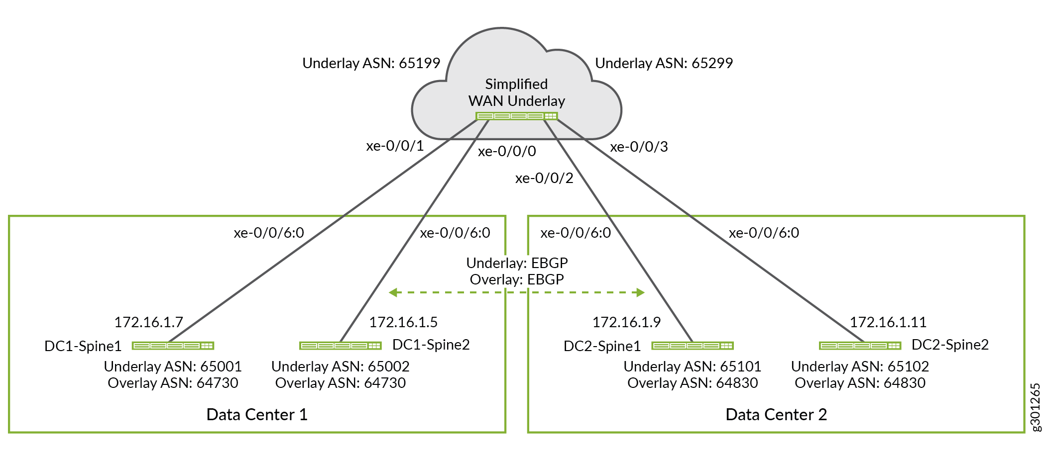
Simplified WAN router configuration for testing.
The focus of this example is on the configuration and operation of the spine devices for OTT DCI. As a result the WAN underlay is treated opaquely. From the perspective of the spine devices the WAN routers, and whatever complexity is used in the WAN cloud, for example an MPLS-based Layer 3 VPN, is of no concern. The spines simply use their local BGP peering to exchange underlay routes for the loopback addresses used in each DC.
A simplified WAN router configuration is provided to help in testing and to better illustrate the functionality provided by the WAN cloud, from the perspective of the spine devices. Figure 2 provides a topology that can be used for testing with a single routing device acting as a WAN cloud.
set interfaces xe-0/0/0 unit 0 family inet address 172.16.1.4/31
set interfaces xe-0/0/1 unit 0 family inet address 172.16.1.6/31
set interfaces xe-0/0/2 unit 0 family inet address 172.16.1.8/31
set interfaces xe-0/0/3 unit 0 family inet address 172.16.1.10/31
set routing-options autonomous-system 65299
set routing-options forwarding-table export ECMP-POLICY
set protocols bgp group UNDERLAY authentication-key "samplepassword-fortesting"
set protocols bgp group UNDERLAY export dci
set protocols bgp group UNDERLAY bfd-liveness-detection minimum-interval 350
set protocols bgp group UNDERLAY bfd-liveness-detection multiplier 3
set protocols bgp group UNDERLAY multipath multiple-as
set protocols bgp group UNDERLAY neighbor 172.16.1.9 peer-as 65101
set protocols bgp group UNDERLAY neighbor 172.16.1.11 peer-as 65102
set protocols bgp group UNDERLAY neighbor 172.16.1.7 peer-as 65001
set protocols bgp group UNDERLAY neighbor 172.16.1.7 local-as 65199
set protocols bgp group UNDERLAY neighbor 172.16.1.5 peer-as 65002
set protocols bgp group UNDERLAY neighbor 172.16.1.5 local-as 65199
set policy-options policy-statement dci term 1 from protocol direct
set policy-options policy-statement dci term 1 then accept
set policy-options policy-statement ECMP-POLICY then load-balance per-packet