How to Configure an IP Clos Fabric for a Campus Network
Requirements
This configuration example uses the following devices:
Two EX9200 or QFX10000 switches as core devices, Software version: Junos OS Release 20.2R3
Two EX4650 or QFX5120 switches as distribution devices, Software version: Junos OS Release 20.2R3
Two EX4300-MP switches as the access layer, Software version: Junos OS Release 20.2R3 or Two EX4400 switches, Software version: Junos OS Release 21.1R1.
One SRX650 security device
One WAN router
Juniper Access Points
Overview
Use this network configuration example to deploy a single campus fabric with a Layer 3 IP-based underlay network that uses EVPN as the control plane protocol and VXLAN as the data plane protocol in the overlay network.
We will first configure EBGP as the underlay routing protocol to exchange loopback routes. Then, we will configure IBGP between the core and distribution devices in the overlay to share reachability information about endpoints in the fabric.
Topology
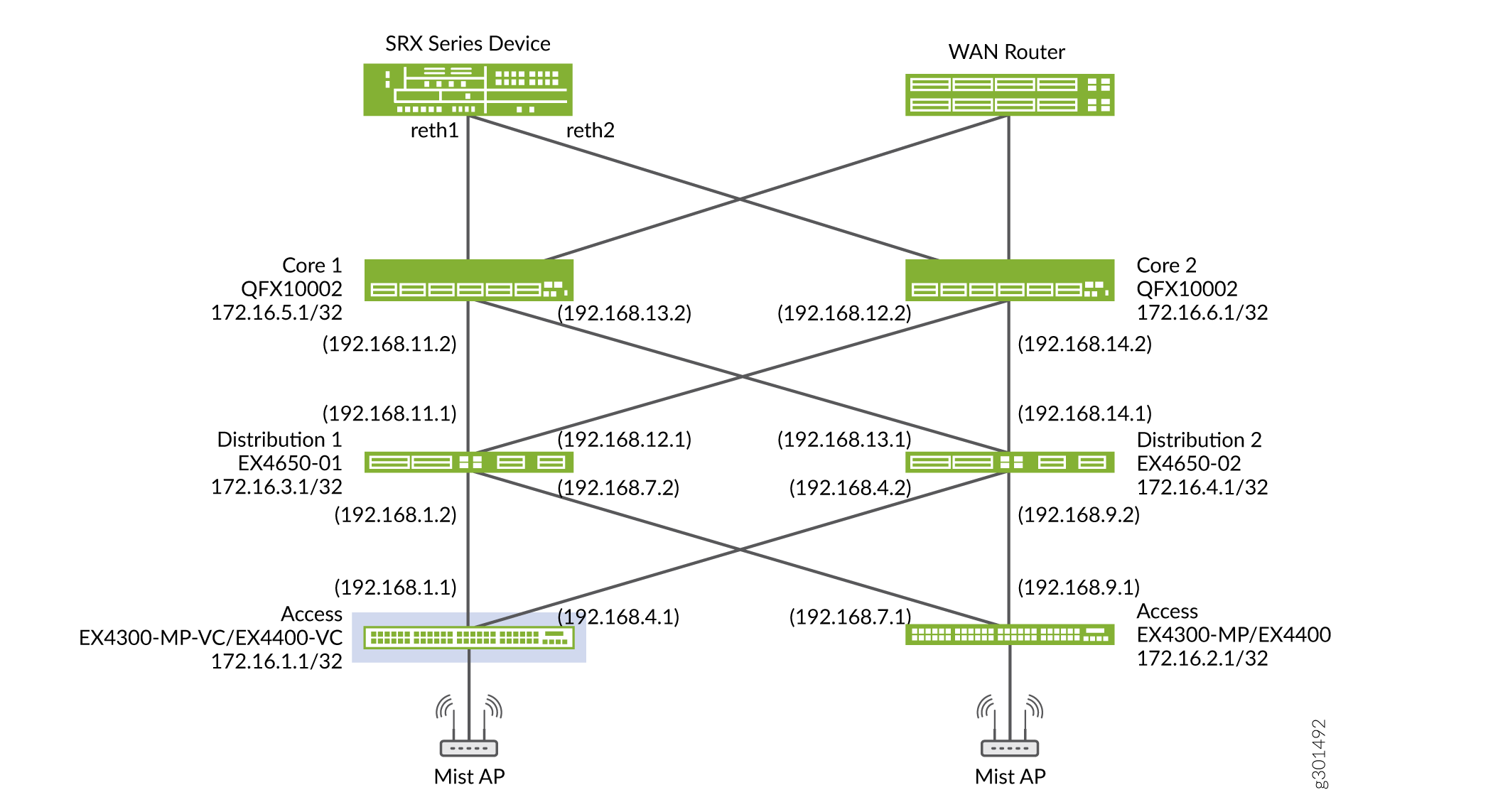
In this example, we configure each device with a /32 loopback address. Figure 1 shows the physical topology with an SRX series device, WAN router, access layer devices (EX-4300-MP), and it shows the IP addressing scheme that is used in this example. The SRX series router enforces policy rules for transit traffic by controlling traffic flow. It allows traffic that can pass through and denies the traffic that is not permitted based on the security policy that is created.
Configure the Underlay IP Fabric
Overview
This section shows how to configure the IP fabric underlay on the core, distribution, and access layer switches using EBGP and how to configure the policy rules on the SRX server.
Interface and Underlay Configuration
Use this section to configure the underlay on the core and distribution layer switches.
- Core 1 Configuration
- Core 2 Configuration
- Distribution 1 Configuration
- Distribution 2 Configuration
- Access switch 1 Configuration
- Access Switch 2 Configuration
- SRX Configuration
Core 1 Configuration
Step-by-Step Procedure
Configure the interfaces connected to the core devices.
set interfaces xe-0/0/3:0 unit 0 family inet address 192.168.11.2/24
set interfaces xe-0/0/3:1 unit 0 family inet address 192.168.13.2/24
Configure the loopback interface and router ID and enable per-packet load balancing
set interfaces lo0 unit 0 family inet address 172.16.5.1/32
set routing-options router-id 172.16.5.1
set routing-options forwarding-table export ecmp_policy
set policy-options policy-statement ecmp_policy then load-balance per-packet
set policy-options policy-statement ecmp_policy then accept
Configure the BGP underlay network.
set groups UnderlayBGP policy-options policy-statement underlay-clos-export term loopback from interface lo0.0
set groups UnderlayBGP policy-options policy-statement underlay-clos-export term loopback then accept
set groups UnderlayBGP protocols bgp group underlay-bgp type external
set groups UnderlayBGP protocols bgp group underlay-bgp export underlay-clos-export
set groups UnderlayBGP protocols bgp group underlay-bgp local-as 4200000005
set groups UnderlayBGP protocols bgp group underlay-bgp multipath multiple-as
set groups UnderlayBGP protocols bgp group underlay-bgp bfd-liveness-detection minimum-interval 1000
set groups UnderlayBGP protocols bgp group underlay-bgp bfd-liveness-detection multiplier 3
set groups UnderlayBGP protocols bgp group underlay-bgp bfd-liveness-detection session-mode automatic
set groups UnderlayBGP protocols bgp group underlay-bgp neighbor 192.168.13.1 peer-as 4200000004
set groups UnderlayBGP protocols bgp group underlay-bgp neighbor 192.168.11.1 peer-as 4200000003
set apply-groups UnderlayBGP
Core 2 Configuration
Step-by-Step Procedure
Configure the interfaces connected to the core devices.
set interfaces xe-0/0/30:0 unit 0 family inet address 192.168.12.2/24
set interfaces xe-0/0/30:3 unit 0 family inet address 192.168.14.2/24
Configure the loopback interface and router ID and enable per-packet load balancing.
set interfaces lo0 unit 0 family inet address 172.16.6.1/32
set routing-options router-id 172.16.6.1
set policy-options policy-statement ecmp_policy then load-balance per-packet
set policy-options policy-statement ecmp_policy then accept
set routing-options forwarding-table export ecmp_policy
Configure the BGP underlay network.
set groups UnderlayBGP policy-options policy-statement underlay-clos-export term loopback from interface lo0.0
set groups UnderlayBGP policy-options policy-statement underlay-clos-export term loopback then accept
set groups UnderlayBGP protocols bgp group underlay-bgp type external
set groups UnderlayBGP protocols bgp group underlay-bgp export underlay-clos-export
set groups UnderlayBGP protocols bgp group underlay-bgp local-as 4200000006
set groups UnderlayBGP protocols bgp group underlay-bgp multipath multiple-as
set groups UnderlayBGP protocols bgp group underlay-bgp bfd-liveness-detection minimum-interval 1000
set groups UnderlayBGP protocols bgp group underlay-bgp bfd-liveness-detection multiplier 3
set groups UnderlayBGP protocols bgp group underlay-bgp bfd-liveness-detection session-mode automatic
set groups UnderlayBGP protocols bgp group underlay-bgp neighbor 192.168.14.1 peer-as 4200000004
set groups UnderlayBGP protocols bgp group underlay-bgp neighbor 192.168.12.1 peer-as 4200000003
set apply-groups UnderlayBGP
Distribution 1 Configuration
Step-by-Step Procedure
Configure the interconnect interfaces between the two core devices and the connectivity to the distribution switches.
set interfaces ge-0/0/12 unit 0 family inet address 192.168.1.2/24
set interfaces ge-0/0/9 unit 0 family inet address 192.168.7.2/24
set interfaces xe-0/0/3 unit 0 family inet address 192.168.11.1/24
set interfaces xe-0/0/4 unit 0 family inet address 192.168.12.1/24
Configure the loopback interface and router ID.
set interfaces lo0 unit 0 family inet address 172.16.3.1/32
set routing-options router-id 172.16.3.1
Enable per-packet load balancing.
set routing-options forwarding-table export ecmp_policy
set policy-options policy-statement ecmp_policy then load-balance per-packet
set policy-options policy-statement ecmp_policy then accept
Configure the BGP underlay network.
set groups UnderlayBGP policy-options policy-statement underlay-clos-export term loopback from interface lo0.0
set groups UnderlayBGP policy-options policy-statement underlay-clos-export term loopback then accept
set groups UnderlayBGP protocols bgp group underlay-bgp type external
set groups UnderlayBGP protocols bgp group underlay-bgp export underlay-clos-export
set groups UnderlayBGP protocols bgp group underlay-bgp local-as 4200000003
set groups UnderlayBGP protocols bgp group underlay-bgp multipath multiple-as
set groups UnderlayBGP protocols bgp group underlay-bgp bfd-liveness-detection minimum-interval 1000
set groups UnderlayBGP protocols bgp group underlay-bgp bfd-liveness-detection multiplier 3
set groups UnderlayBGP protocols bgp group underlay-bgp bfd-liveness-detection session-mode automatic
set groups UnderlayBGP protocols bgp group underlay-bgp neighbor 192.168.1.1 peer-as 4200000001
set groups UnderlayBGP protocols bgp group underlay-bgp neighbor 192.168.7.1 peer-as 4200000002
set groups UnderlayBGP protocols bgp group underlay-bgp neighbor 192.168.11.2 peer-as 4200000005
set groups UnderlayBGP protocols bgp group underlay-bgp neighbor 192.168.12.2 peer-as 4200000006
set apply-groups UnderlayBGP
Distribution 2 Configuration
Step-by-Step Procedure
Configure the interconnect interfaces between the two core devices and the connectivity to distribution switches.
set interfaces ge-0/0/9 unit 0 family inet address 192.168.9.2/24
set interfaces xe-0/0/3 unit 0 family inet address 192.168.13.1/24
set interfaces xe-0/0/4 unit 0 family inet address 192.168.14.1/24
set interfaces ge-0/0/12 unit 0 family inet address 192.168.4.2/24
Configure the loopback interface and router ID.
set interfaces lo0 unit 0 family inet address 172.16.4.1/32
set routing-options router-id 172.16.4.1
Enable per-packet load balancing.
set routing-options forwarding-table export ecmp_policy
set policy-options policy-statement ecmp_policy then load-balance per-packet
set policy-options policy-statement ecmp_policy then accept
Configure the BGP underlay network.
set groups UnderlayBGP policy-options policy-statement underlay-clos-export term loopback from interface lo0.0
set groups UnderlayBGP policy-options policy-statement underlay-clos-export term loopback then accept
set groups UnderlayBGP protocols bgp group underlay-bgp type external
set groups UnderlayBGP protocols bgp group underlay-bgp export underlay-clos-export
set groups UnderlayBGP protocols bgp group underlay-bgp local-as 4200000004
set groups UnderlayBGP protocols bgp group underlay-bgp multipath multiple-as
set groups UnderlayBGP protocols bgp group underlay-bgp bfd-liveness-detection minimum-interval 1000
set groups UnderlayBGP protocols bgp group underlay-bgp bfd-liveness-detection multiplier 3
set groups UnderlayBGP protocols bgp group underlay-bgp bfd-liveness-detection session-mode automatic
set groups UnderlayBGP protocols bgp group underlay-bgp neighbor 192.168.9.1 peer-as 4200000002
set groups UnderlayBGP protocols bgp group underlay-bgp neighbor 192.168.13.2 peer-as 4200000005
set groups UnderlayBGP protocols bgp group underlay-bgp neighbor 192.168.14.2 peer-as 4200000006
set groups UnderlayBGP protocols bgp group underlay-bgp neighbor 192.168.4.1 peer-as 4200000001
set apply-groups UnderlayBGP
Access switch 1 Configuration
Step-by-Step Procedure
Specify the interfaces that connect to the distribution switches.
set interfaces ge-0/0/1 unit 0 family inet address 192.168.4.1/24
set interfaces ge-0/0/2 unit 0 family inet address 192.168.1.1/24
set interfaces lo0 unit 0 family inet address 172.16.1.1/32
(Optional) Configure a Virtual Chassis with non-stop routing and bridging for high availability.
set groups nsr_nsb system commit synchronize
set groups nsr_nsb chassis redundancy graceful-switchover
set groups nsr_nsb routing-options nonstop-routing
set groups nsr_nsb protocols layer2-control nonstop-bridging
set apply-groups nsr_nsb
set groups vc virtual-chassis preprovisioned
set groups vc virtual-chassis member 0 role routing-engine
set groups vc virtual-chassis member 0 serial-number XR0220140070
set groups vc virtual-chassis member 1 role routing-engine
set groups vc virtual-chassis member 1 serial-number XR0220140059
set groups vc virtual-chassis member 2 role line-card
set groups vc virtual-chassis member 2 serial-number XR0220140068
set apply-groups vc
Configure the underlay BGP.
set groups UnderlayBGP policy-options policy-statement underlay-clos-export term loopback from interface lo0.0
set groups UnderlayBGP policy-options policy-statement underlay-clos-export term loopback then accept
set groups UnderlayBGP protocols bgp group underlay-bgp type external
set groups UnderlayBGP protocols bgp group underlay-bgp export underlay-clos-export
set groups UnderlayBGP protocols bgp group underlay-bgp local-as 4200000001
set groups UnderlayBGP protocols bgp group underlay-bgp multipath multiple-as
set groups UnderlayBGP protocols bgp group underlay-bgp bfd-liveness-detection minimum-interval 1000
set groups UnderlayBGP protocols bgp group underlay-bgp bfd-liveness-detection multiplier 3
set groups UnderlayBGP protocols bgp group underlay-bgp bfd-liveness-detection session-mode automatic
set groups UnderlayBGP protocols bgp group underlay-bgp neighbor 192.168.1.2 peer-as 4200000003
set groups UnderlayBGP protocols bgp group underlay-bgp neighbor 192.168.4.2 peer-as 4200000004
set apply-groups UnderlayBGP
Access Switch 2 Configuration
Step-by-Step Procedure
Specify the interfaces to connect to distribution switches.
set interfaces ge-0/0/1 unit 0 family inet address 192.168.9.1/24
set interfaces ge-0/0/2 unit 0 family inet address 192.168.7.1/24
set interfaces lo0 unit 0 family inet address 172.16.2.1/32
(Optional) Configure a Virtual Chassis with non-stop routing and bridging for high availability.
set groups nsr_nsb system commit synchronize
set groups nsr_nsb chassis redundancy graceful-switchover
set groups nsr_nsb routing-options nonstop-routing
set groups nsr_nsb protocols layer2-control nonstop-bridging
set apply-groups nsr_nsb
set groups vc virtual-chassis preprovisioned
set groups vc virtual-chassis member 0 role routing-engine
set groups vc virtual-chassis member 0 serial-number XR0220190261
set groups vc virtual-chassis member 1 role routing-engine
set groups vc virtual-chassis member 1 serial-number XR0220190270
set apply-groups vc
Configure the underlay BGP.
set groups UnderlayBGP policy-options policy-statement underlay-clos-export term loopback from interface lo0.0
set groups UnderlayBGP policy-options policy-statement underlay-clos-export term loopback then accept
set groups UnderlayBGP protocols bgp group underlay-bgp type external
set groups UnderlayBGP protocols bgp group underlay-bgp export underlay-clos-export
set groups UnderlayBGP protocols bgp group underlay-bgp local-as 4200000002
set groups UnderlayBGP protocols bgp group underlay-bgp multipath multiple-as
set groups UnderlayBGP protocols bgp group underlay-bgp bfd-liveness-detection minimum-interval 1000
set groups UnderlayBGP protocols bgp group underlay-bgp bfd-liveness-detection multiplier 3
set groups UnderlayBGP protocols bgp group underlay-bgp bfd-liveness-detection session-mode automatic
set groups UnderlayBGP protocols bgp group underlay-bgp neighbor 192.168.7.2 peer-as 4200000003
set groups UnderlayBGP protocols bgp group underlay-bgp neighbor 192.168.9.2 peer-as 4200000004
set apply-groups UnderlayBGP
If you have additional access layer switches in your network, repeat this configuration procedure for each access switch.
SRX Configuration
Step-by-Step Procedure
Configure security settings on the SRX device.
set security nat source rule-set trust-to-untrust from zone trust
set security nat source rule-set trust-to-untrust to zone untrust
set security nat source rule-set trust-to-untrust rule source-nat-rule match source-address 0.0.0.0/0
set security nat source rule-set trust-to-untrust rule source-nat-rule then source-nat interface
set security policies from-zone trust to-zone trust policy trust-to-trust match source-address any
set security policies from-zone trust to-zone trust policy trust-to-trust match destination-address any
set security policies from-zone trust to-zone trust policy trust-to-trust match application any
set security policies from-zone trust to-zone trust policy trust-to-trust then permit
set security policies from-zone trust to-zone untrust policy trust-to-untrust match source-address any
set security policies from-zone trust to-zone untrust policy trust-to-untrust match destination-address any
set security policies from-zone trust to-zone untrust policy trust-to-untrust match application any
set security policies from-zone trust to-zone untrust policy trust-to-untrust then permit
set security zones security-zone trust host-inbound-traffic system-services ping
set security zones security-zone trust host-inbound-traffic system-services all
set security zones security-zone trust host-inbound-traffic protocols all
set security zones security-zone trust interfaces ge-0/0/1.0
set security zones security-zone trust interfaces ge-0/0/2.0
set security zones security-zone untrust interfaces ge-0/0/4.0 host-inbound-traffic system-services dhcp
set security zones security-zone untrust interfaces ge-0/0/4.0 host-inbound-traffic system-services tftp
set interfaces ge-0/0/1 unit 0 family inet address 10.16.5.1/24
set interfaces ge-0/0/2 unit 0 family inet address 10.16.6.1/24
set interfaces ge-0/0/4 unit 0 family inet address 10.204.46.136/20
Configure the Overlay
Overview
This section shows how to configure the overlay, including configuring IBGP peerings, the VLAN to VXLAN mappings, and the IRB interface configurations for the virtual networks on the access switches.
Topology
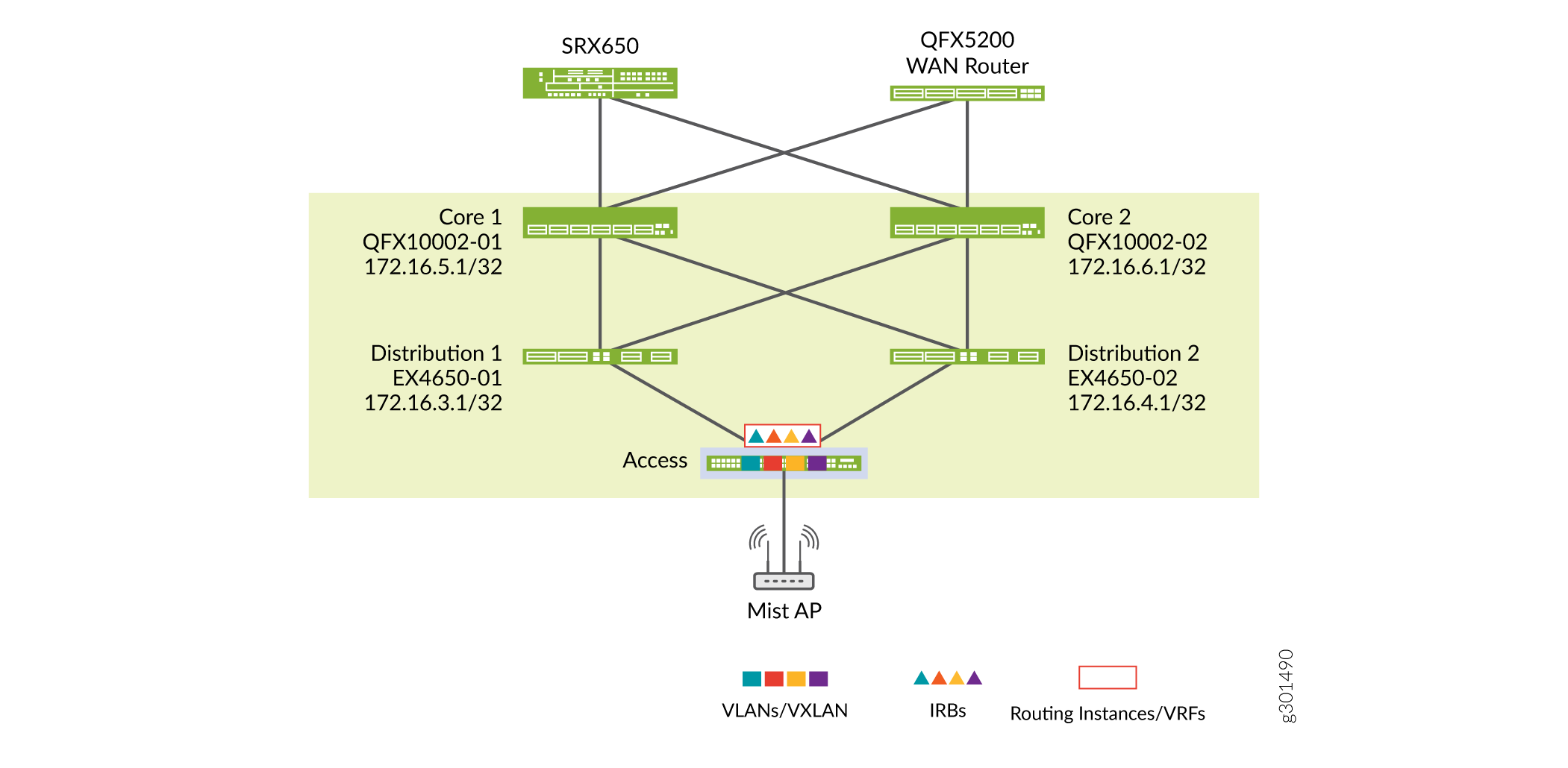
In this example, we have three virtual networks: 1, 2, and 3. The IRB interfaces for these virtual networks are on the access switches. We placed all IRB interfaces in the same routing instance. You can place the IRB interfaces in different routing instances for network segmentation if it is needed in your deployment.
Figure 2 shows the overlay virtual network with VLANs.
Overlay and Virtual Network Configuration
Use this section to configure the overlay on the core and distribution layer switches.
- Core 1 Configuration
- Core 2 Configuration
- Distribution 1 Configuration
- Distribution 2 Configuration
- Access 1 Configuration
- Access 2 Configuration
Core 1 Configuration
Step-by-Step Procedure
Set the AS number and configure IBGP neighbors between core and distribution devices. You do not need to configure IBGP neighbors between Core 1 and Core 2 because they receive all BGP updates from Distribution 1 and Distribution 2.
Configure the core devices as route reflectors to eliminate the need for a full IBGP mesh between all distribution layer switches. This makes the configuration on the distribution layer devices simple and consistent.
set routing-options autonomous-system 100
set protocols bgp group cluster-rr type internal
set protocols bgp group cluster-rr local-address 172.16.5.1
set protocols bgp group cluster-rr mtu-discovery
set protocols bgp group cluster-rr family evpn signaling
set protocols bgp group cluster-rr cluster 172.16.5.1
set protocols bgp group cluster-rr multipath
set protocols bgp group cluster-rr bfd-liveness-detection minimum-interval 1000
set protocols bgp group cluster-rr bfd-liveness-detection multiplier 3
set protocols bgp group cluster-rr bfd-liveness-detection session-mode automatic
set protocols bgp group cluster-rr neighbor 172.16.3.1
set protocols bgp group cluster-rr neighbor 172.16.4.1
set protocols bgp group cluster-rr vpn-apply-export
Core 2 Configuration
Step-by-Step Procedure
Set the AS number and configure IBGP neighbors between core and distribution devices. Configure the core devices as route reflectors to eliminate the need for full mesh IBGP configuration between all distribution and access layer devices.
set routing-options autonomous-system 100
set protocols bgp group cluster-rr type internal
set protocols bgp group cluster-rr local-address 172.16.6.1
set protocols bgp group cluster-rr mtu-discovery
set protocols bgp group cluster-rr family evpn signaling
set protocols bgp group cluster-rr cluster 172.16.5.1
set protocols bgp group cluster-rr multipath
set protocols bgp group cluster-rr bfd-liveness-detection minimum-interval 1000
set protocols bgp group cluster-rr bfd-liveness-detection multiplier 3
set protocols bgp group cluster-rr bfd-liveness-detection session-mode automatic
set protocols bgp group cluster-rr neighbor 172.16.3.1
set protocols bgp group cluster-rr neighbor 172.16.4.1
set protocols bgp group cluster-rr vpn-apply-export
Distribution 1 Configuration
Step-by-Step Procedure
Configure IBGP neighbors from the distribution switch to the core switches.
set routing-options autonomous-system 100
set groups OverlayBGP protocols bgp group cluster-pod1 type internal
set groups OverlayBGP protocols bgp group cluster-pod1 local-address 172.16.3.1
set groups OverlayBGP protocols bgp group cluster-pod1 mtu-discovery
set groups OverlayBGP protocols bgp group cluster-pod1 family evpn signaling
set groups OverlayBGP protocols bgp group cluster-pod1 cluster 172.16.3.1
set groups OverlayBGP protocols bgp group cluster-pod1 multipath
set groups OverlayBGP protocols bgp group cluster-pod1 bfd-liveness-detection minimum-interval 1000
set groups OverlayBGP protocols bgp group cluster-pod1 bfd-liveness-detection multiplier 3
set groups OverlayBGP protocols bgp group cluster-pod1 bfd-liveness-detection session-mode automatic
set groups OverlayBGP protocols bgp group cluster-pod1 neighbor 172.16.1.1
set groups OverlayBGP protocols bgp group cluster-pod1 neighbor 172.16.2.1
set groups OverlayBGP protocols bgp group cluster-pod1 neighbor 172.16.5.1
set groups OverlayBGP protocols bgp group cluster-pod1 neighbor 172.16.6.1
set groups OverlayBGP protocols bgp group cluster-pod1 vpn-apply-export
set apply-groups OverlayBGP
Distribution 2 Configuration
Step-by-Step Procedure
Configure IBGP neighbors from the distribution switch to the core switches.
set routing-options autonomous-system 100
set groups OverlayBGP protocols bgp group cluster-pod1 type internal
set groups OverlayBGP protocols bgp group cluster-pod1 local-address 172.16.4.1
set groups OverlayBGP protocols bgp group cluster-pod1 mtu-discovery
set groups OverlayBGP protocols bgp group cluster-pod1 family evpn signaling
set groups OverlayBGP protocols bgp group cluster-pod1 cluster 172.16.3.1
set groups OverlayBGP protocols bgp group cluster-pod1 multipath
set groups OverlayBGP protocols bgp group cluster-pod1 bfd-liveness-detection minimum-interval 1000
set groups OverlayBGP protocols bgp group cluster-pod1 bfd-liveness-detection multiplier 3
set groups OverlayBGP protocols bgp group cluster-pod1 bfd-liveness-detection session-mode automatic
set groups OverlayBGP protocols bgp group cluster-pod1 neighbor 172.16.1.1
set groups OverlayBGP protocols bgp group cluster-pod1 neighbor 172.16.2.1
set groups OverlayBGP protocols bgp group cluster-pod1 neighbor 172.16.5.1
set groups OverlayBGP protocols bgp group cluster-pod1 neighbor 172.16.6.1
set groups OverlayBGP protocols bgp group cluster-pod1 vpn-apply-export
set apply-groups OverlayBGP
Access 1 Configuration
Step-by-Step Procedure
Configure the overlay BGP.
set routing-options router-id 172.16.1.1
set routing-options autonomous-system 100
set groups OverlayBGP protocols bgp group cluster-pod1 type internal
set groups OverlayBGP protocols bgp group cluster-pod1 local-address 172.16.1.1
set groups OverlayBGP protocols bgp group cluster-pod1 mtu-discovery
set groups OverlayBGP protocols bgp group cluster-pod1 family evpn signaling
set groups OverlayBGP protocols bgp group cluster-pod1 multipath
set groups OverlayBGP protocols bgp group cluster-pod1 bfd-liveness-detection minimum-interval 1000
set groups OverlayBGP protocols bgp group cluster-pod1 bfd-liveness-detection multiplier 3
set groups OverlayBGP protocols bgp group cluster-pod1 bfd-liveness-detection session-mode automatic
set groups OverlayBGP protocols bgp group cluster-pod1 neighbor 172.16.3.1
set groups OverlayBGP protocols bgp group cluster-pod1 neighbor 172.16.4.1
set groups OverlayBGP protocols bgp group cluster-pod1 vpn-apply-export
set apply-groups OverlayBGP
Configure EVPN-VXLAN.
set switch-options vtep-source-interface lo0.0
set switch-options route-distinguisher 172.16.1.1:10
set switch-options vrf-target target:65000:1111
set switch-options vrf-target auto
set forwarding-options vxlan-routing next-hop 16384
set forwarding-options vxlan-routing interface-num 6144
set forwarding-options vxlan-routing overlay-ecmp
set protocols evpn encapsulation vxlan
set protocols evpn default-gateway no-gateway-community
set protocols evpn remote-ip-host-routes
set protocols evpn extended-vni-list all
Configure the VLAN/VXLAN mapping and IRB interfaces. VLAN_1 is used to send management traffic from Mist APs to the Internet. Configure VLAN_2 and VLAN_3 to connect wired and wireless client devices
set groups EP-VLAN-1-52 vlans EP-VLAN-1 vlan-id 1
set groups EP-VLAN-1-52 vlans EP-VLAN-1 l3-interface irb.1
set groups EP-VLAN-1-52 vlans EP-VLAN-1 vxlan vni 100001
set groups EP-VLAN-1-52 vlans EP-VLAN-2 vlan-id 2
set groups EP-VLAN-1-52 vlans EP-VLAN-2 l3-interface irb.2
set groups EP-VLAN-1-52 vlans EP-VLAN-2 vxlan vni 100002
set groups EP-VLAN-1-52 vlans EP-VLAN-3 vlan-id 3
set groups EP-VLAN-1-52 vlans EP-VLAN-3 l3-interface irb.3
set groups EP-VLAN-1-52 vlans EP-VLAN-3 vxlan vni 100003
set groups EP-VLAN-1-52 interfaces irb unit 1 family inet address 10.0.1.241/24 preferred
set groups EP-VLAN-1-52 interfaces irb unit 1 family inet6 nd6-stale-time 3600
set groups EP-VLAN-1-52 interfaces irb unit 1 family inet6 address 2001:db8::10:0:1:241/112 preferred
set groups EP-VLAN-1-52 interfaces irb unit 2 family inet address 10.0.2.241/24 preferred
set groups EP-VLAN-1-52 interfaces irb unit 2 family inet6 nd6-stale-time 3600
set groups EP-VLAN-1-52 interfaces irb unit 2 family inet6 address 2001:db8::10:0:2:241/112 preferred
set groups EP-VLAN-1-52 interfaces irb unit 3 family inet address 10.0.3.241/24 preferred
set groups EP-VLAN-1-52 interfaces irb unit 3 family inet6 nd6-stale-time 3600
set groups EP-VLAN-1-52 interfaces irb unit 3 family inet6 address 2001:db8::10:0:3:241/112 preferred
set apply-group EP-VLAN-1-52
Configure the VRF instance.
set groups VRF-TYPE-2-BD-1-52 routing-instances VRF-ep-type2-1 instance-type vrf
set groups VRF-TYPE-2-BD-1-52 routing-instances VRF-ep-type2-1 interface lo0.1
set groups VRF-TYPE-2-BD-1-52 routing-instances VRF-ep-type2-1 interface irb.1
set groups VRF-TYPE-2-BD-1-52 routing-instances VRF-ep-type2-1 interface irb.2
set groups VRF-TYPE-2-BD-1-52 routing-instances VRF-ep-type2-1 interface irb.3
set groups VRF-TYPE-2-BD-1-52 routing-instances VRF-ep-type2-1 route-distinguisher 172.16.1.1:1
set groups VRF-TYPE-2-BD-1-52 routing-instances VRF-ep-type2-1 vrf-target target:100:1
set apply-group VRF-TYPE-2-BD-1-52
Configure the ports for the Mist Access Points as trunk ports. This allows you to use multiple SSID and VLANs on the port. VLAN_1 is used to send management traffic from Mist APs to the Internet. Configure VLAN_2 and VLAN_3 to connect wired and wireless client devices.
set routing-options static route 0.0.0.0/0 next-hop 172.31.25.2
set interfaces mge-0/0/25 mtu 9200
set interfaces mge-0/0/25 unit 0 family ethernet-switching interface-mode trunk
set interfaces mge-0/0/25 unit 0 family ethernet-switching vlan members vlan_1
set poe interface mge-0/0/25
set interfaces irb mtu 9200
Configure 802.1x authentication for the wired clients.
set access profile 802.1X-PROFILE-1 accounting-order radius
set access profile 802.1X-PROFILE-1 authentication-order radius
set access profile 802.1X-PROFILE-1 radius authentication-server 10.204.32.234
set access profile 802.1X-PROFILE-1 radius accounting-server 10.204.32.234
set access profile 802.1X-PROFILE-1 radius options nas-identifier access-switch-1
set access profile 802.1X-PROFILE-1 accounting order radius
set access profile 802.1X-PROFILE-1 accounting address-change-immediate-update
set groups DOT1X protocols dot1x authenticator authentication-profile-name 802.1X-PROFILE-1
set groups DOT1X protocols dot1x authenticator no-mac-table-binding
set groups DOT1X protocols dot1x authenticator interface mge-1/0/44.0 authentication-order dot1x
set groups DOT1X protocols dot1x authenticator interface mge-1/0/44.0 authentication-order mac-radius
set groups DOT1X protocols dot1x authenticator interface mge-1/0/44.0 supplicant multiple
set groups DOT1X protocols dot1x authenticator interface mge-1/0/44.0 transmit-period 30
set groups DOT1X protocols dot1x authenticator interface mge-1/0/44.0 mac-radius
set groups DOT1X protocols dot1x authenticator interface mge-1/0/44.0 reauthentication 3600
set groups DOT1X protocols dot1x authenticator interface mge-1/0/44.0 server-timeout 30
set groups DOT1X protocols dot1x authenticator interface mge-1/0/44.0 maximum-requests 10
set apply-groups DOT1X
Access 2 Configuration
Step-by-Step Procedure
Configure the overlay BGP
set routing-options router-id 172.16.2.1
set routing-options autonomous-system 100
set groups OverlayBGP protocols bgp group cluster-pod1 type internal
set groups OverlayBGP protocols bgp group cluster-pod1 local-address 172.16.2.1
set groups OverlayBGP protocols bgp group cluster-pod1 mtu-discovery
set groups OverlayBGP protocols bgp group cluster-pod1 family evpn signaling
set groups OverlayBGP protocols bgp group cluster-pod1 multipath
set groups OverlayBGP protocols bgp group cluster-pod1 bfd-liveness-detection minimum-interval 1000
set groups OverlayBGP protocols bgp group cluster-pod1 bfd-liveness-detection multiplier 3
set groups OverlayBGP protocols bgp group cluster-pod1 bfd-liveness-detection session-mode automatic
set groups OverlayBGP protocols bgp group cluster-pod1 neighbor 172.16.3.1
set groups OverlayBGP protocols bgp group cluster-pod1 neighbor 172.16.4.1
set groups OverlayBGP protocols bgp group cluster-pod1 vpn-apply-export
set apply-groups OverlayBGP
Configure EVPN-VXLAN.
set switch-options vtep-source-interface lo0.0
set switch-options route-distinguisher 172.16.1.1:10
set switch-options vrf-target target:65000:1111
set switch-options vrf-target auto
set forwarding-options vxlan-routing next-hop 16384
set forwarding-options vxlan-routing interface-num 6144
set forwarding-options vxlan-routing overlay-ecmp
set protocols evpn encapsulation vxlan
set protocols evpn default-gateway no-gateway-community
set protocols evpn remote-ip-host-routes
set protocols evpn extended-vni-list all
Configure the VLAN/VXLAN mapping and IRB.
set groups EP-VLAN-1-52 vlans EP-VLAN-1 vlan-id 1
set groups EP-VLAN-1-52 vlans EP-VLAN-1 l3-interface irb.1
set groups EP-VLAN-1-52 vlans EP-VLAN-1 vxlan vni 100001
set groups EP-VLAN-1-52 vlans EP-VLAN-2 vlan-id 2
set groups EP-VLAN-1-52 vlans EP-VLAN-2 l3-interface irb.2
set groups EP-VLAN-1-52 vlans EP-VLAN-2 vxlan vni 100002
set groups EP-VLAN-1-52 vlans EP-VLAN-3 vlan-id 3
set groups EP-VLAN-1-52 vlans EP-VLAN-3 l3-interface irb.3
set groups EP-VLAN-1-52 vlans EP-VLAN-3 vxlan vni 100003
set groups EP-VLAN-1-52 interfaces irb unit 1 family inet address 10.0.1.242/24 preferred
set groups EP-VLAN-1-52 interfaces irb unit 1 family inet6 nd6-stale-time 3600
set groups EP-VLAN-1-52 interfaces irb unit 1 family inet6 address 2001:db8::10:0:1:242/112 preferred
set groups EP-VLAN-1-52 interfaces irb unit 2 family inet address 10.0.2.242/24 preferred
set groups EP-VLAN-1-52 interfaces irb unit 2 family inet6 nd6-stale-time 3600
set groups EP-VLAN-1-52 interfaces irb unit 2 family inet6 address 2001:db8::10:0:2:242/112 preferred
set groups EP-VLAN-1-52 interfaces irb unit 3 family inet address 10.0.3.242/24 preferred
set groups EP-VLAN-1-52 interfaces irb unit 3 family inet6 nd6-stale-time 3600
set groups EP-VLAN-1-52 interfaces irb unit 3 family inet6 address 2001:db8::10:0:3:242/112 preferred
set apply-group EP-VLAN-1-52
Configure the VRF instance.
set groups VRF-TYPE-2-BD-1-52 routing-instances VRF-ep-type2-1 instance-type vrf
set groups VRF-TYPE-2-BD-1-52 routing-instances VRF-ep-type2-1 interface lo0.1
set groups VRF-TYPE-2-BD-1-52 routing-instances VRF-ep-type2-1 interface irb.1
set groups VRF-TYPE-2-BD-1-52 routing-instances VRF-ep-type2-1 interface irb.2
set groups VRF-TYPE-2-BD-1-52 routing-instances VRF-ep-type2-1 interface irb.3
set groups VRF-TYPE-2-BD-1-52 routing-instances VRF-ep-type2-1 interface irb.4
set groups VRF-TYPE-2-BD-1-52 routing-instances VRF-ep-type2-1 route-distinguisher 172.16.2.1:1
set groups VRF-TYPE-2-BD-1-52 routing-instances VRF-ep-type2-1 vrf-target target:100:1
set groups VRF-TYPE-2-BD-1-52 interfaces lo0 unit 1 family inet
set apply-group VRF-TYPE-2-BD-1-52
Configure the ports for the Mist Access Points as trunk ports. This allows you to support multiple SSID and VLANs on the port. VLAN_1 is used to send management traffic from Mist APs to the Internet. Configure VLAN_2 and VLAN_3 to connect wired and wireless client devices.
set routing-options static route 0.0.0.0/0 next-hop 172.31.25.2
set interfaces mge-0/0/25 mtu 9200
set interfaces mge-0/0/25 unit 0 family ethernet-switching interface-mode trunk
set interfaces mge-0/0/25 unit 0 family ethernet-switching vlan members vlan_1
set poe interface mge-0/0/25
set interfaces irb mtu 9200
Configure 802.1x authentication for the wired clients.
set access profile 802.1X-PROFILE-1 accounting-order radius
set access profile 802.1X-PROFILE-1 authentication-order radius
set access profile 802.1X-PROFILE-1 radius authentication-server 10.204.32.234
set access profile 802.1X-PROFILE-1 radius accounting-server 10.204.32.234
set access profile 802.1X-PROFILE-1 radius options nas-identifier access-switch-2
set access profile 802.1X-PROFILE-1 accounting order radius
set access profile 802.1X-PROFILE-1 accounting address-change-immediate-update
set groups DOT1X protocols dot1x authenticator authentication-profile-name 802.1X-PROFILE-1
set groups DOT1X protocols dot1x authenticator no-mac-table-binding
set groups DOT1X protocols dot1x authenticator interface mge-1/0/44.0 authentication-order dot1x
set groups DOT1X protocols dot1x authenticator interface mge-1/0/44.0 authentication-order mac-radius
set groups DOT1X protocols dot1x authenticator interface mge-1/0/44.0 supplicant multiple
set groups DOT1X protocols dot1x authenticator interface mge-1/0/44.0 transmit-period 30
set groups DOT1X protocols dot1x authenticator interface mge-1/0/44.0 mac-radius
set groups DOT1X protocols dot1x authenticator interface mge-1/0/44.0 reauthentication 3600
set groups DOT1X protocols dot1x authenticator interface mge-1/0/44.0 server-timeout 30
set groups DOT1X protocols dot1x authenticator interface mge-1/0/44.0 maximum-requests 10
set apply-groups DOT1X
If you have additional access layer switches in your network, repeat this configuration procedure for each access switch.
Verification
Procedure
Step-by-Step Procedure
Overview
Log in to each device and verify that the EVPN-VXLAN fabric has been configured.
Verification
- Distribution 1: Verifying BGP Sessions
- Distribution 2: Verifying BGP Sessions
- Access 1: Verifying EVPN Database Information
- Access 1: Verifying Local Switching Table Information
- Access 2: Verifying EVPN Database Information
- Access 2: Verifying Local Switching Table Information
Distribution 1: Verifying BGP Sessions
Purpose
Verify the state of the BGP sessions with the core and access devices.
Action
Verify that BGP sessions are established with the core devices and access devices. The IP addresses for the core devices are 172.16.5.1 and 172.16.6.1 and the IP addresses for the access devices are 172.16.1.1 and 172.16.2.1
user@distribution-1> show bgp summary
Threading mode: BGP I/O
Groups: 3 Peers: 11 Down peers: 0
Table          Tot Paths  Act Paths Suppressed    History Damp State    Pending
bgp.evpn.0
                     931        914          0          0          0          0
inet.0
                      23         14          0          0          0          0
Peer                     AS      InPkt     OutPkt    OutQ   Flaps Last Up/Dwn State|#Active/Received/Accepted/Damped...
172.16.1.1              100        379        318       0       0       35:40 Establ
  bgp.evpn.0: 273/273/273/0
  default-switch.evpn.0: 5/5/5/0
  __default_evpn__.evpn.0: 0/0/0/0
  VRF-ep-type5-2.evpn.0: 9/9/9/0
172.16.2.1              100        301        357       0       0       35:32 Establ
  bgp.evpn.0: 624/624/624/0
  default-switch.evpn.0: 5/5/5/0
  __default_evpn__.evpn.0: 0/0/0/0
172.16.5.1              100        569        540       0       0       29:53 Establ
  bgp.evpn.0: 17/17/17/0
  default-switch.evpn.0: 14/14/14/0
  __default_evpn__.evpn.0: 1/1/1/0
  VRF-ep-type5-2.evpn.0: 2/2/2/0
172.16.6.1              100        476        541       0       0       30:21 Establ
  bgp.evpn.0: 0/17/17/0
  default-switch.evpn.0: 0/14/14/0
  __default_evpn__.evpn.0: 0/1/1/0
  VRF-ep-type5-2.evpn.0: 0/2/2/0
192.168.1.1      4200000001         77         75       0       0       31:51 Establ
  inet.0: 2/3/3/0
192.168.2.1      4200000001         84         83       0       0       35:42 Establ
  inet.0: 2/3/3/0
192.168.3.1      4200000001         85         84       0       0       35:43 Establ
  inet.0: 2/3/3/0
192.168.7.1      4200000002         83         86       0       0       35:39 Establ
  inet.0: 2/3/3/0
192.168.8.1      4200000002         83         86       0       0       35:35 Establ
  inet.0: 2/3/3/0
192.168.11.2     4200000005         76         74       0       0       30:04 Establ
  inet.0: 2/5/5/0
192.168.12.2     4200000006         72         72       0       0       30:25 Establ
Meaning
BGP is up on both the distribution and core devices. The IBGP sessions are established with the loopback interfaces of the core and access devices using MP-IBGP with EVPN signaling to form the overlay that exchanges EVPN routes.
Distribution 2: Verifying BGP Sessions
Purpose
Verify the state of the BGP sessions with the core and access devices.
Action
Verify that BGP sessions are established with the core devices and access devices. The IP addresses for the core devices are 172.16.5.1 and 172.16.6.1 and the IP addresses for the access devices are 172.16.1.1 and 172.16.2.1.
user@distribution-2> show bgp summary
Threading mode: BGP I/O
Groups: 3 Peers: 11 Down peers: 0
Table          Tot Paths  Act Paths Suppressed    History Damp State    Pending
bgp.evpn.0
                     931        914          0          0          0          0
inet.0
                      26         14          0          0          0          0
Peer                     AS      InPkt     OutPkt    OutQ   Flaps Last Up/Dwn State|#Active/Received/Accepted/Damped...
172.16.1.1              100        390        321       0       0       36:52 Establ
  bgp.evpn.0: 273/273/273/0
  default-switch.evpn.0: 5/5/5/0
  __default_evpn__.evpn.0: 0/0/0/0
  VRF-ep-type5-2.evpn.0: 9/9/9/0
172.16.2.1              100        303        364       0       0       36:32 Establ
  bgp.evpn.0: 624/624/624/0
  default-switch.evpn.0: 5/5/5/0
  __default_evpn__.evpn.0: 0/0/0/0
172.16.5.1              100        555        555       0       0       31:46 Establ
  bgp.evpn.0: 17/17/17/0
  default-switch.evpn.0: 14/14/14/0
  __default_evpn__.evpn.0: 1/1/1/0
  VRF-ep-type5-2.evpn.0: 2/2/2/0
172.16.6.1              100        555        556       0       0       31:49 Establ
  bgp.evpn.0: 0/17/17/0
  default-switch.evpn.0: 0/14/14/0
  __default_evpn__.evpn.0: 0/1/1/0
  VRF-ep-type5-2.evpn.0: 0/2/2/0
192.168.4.1      4200000001         79         77       0       0       33:22 Establ
  inet.0: 2/4/4/0
192.168.5.1      4200000001         88         85       0       0       36:53 Establ
  inet.0: 2/4/4/0
192.168.6.1      4200000001         87         85       0       0       36:49 Establ
  inet.0: 2/4/4/0
192.168.9.1      4200000002         88         91       0       0       36:49 Establ
  inet.0: 2/4/4/0
192.168.10.1     4200000002         88         89       0       0       36:45 Establ
  inet.0: 2/4/4/0
192.168.13.2     4200000005         74         75       0       0       31:48 Establ
  inet.0: 2/2/2/0
192.168.14.2     4200000006         76         77       0       0       31:53 Establ
  inet.0: 2/4/4/0
Meaning
BGP is up on both the distribution and core devices. The IBGP sessions are established with the loopback interfaces of the core and access devices using MP-IBGP with EVPN signaling to form the overlay layer and exchange EVPN routes.
Access 1: Verifying EVPN Database Information
Purpose
Verify that the EVPN database is correctly populated.
Action
Verify that the EVPN database is installing MAC address information for locally attached hosts and receiving advertisements from the other leaf devices with information about remote hosts.
user@access-1> show evpn database
Instance: default-switch
VLAN  DomainId  MAC address        Active source                  Timestamp        IP address
     100001     0c:59:9c:ea:22:dc  172.16.2.1                     Dec 14 01:55:44  10.0.1.242
                                                                                   2001:db8::10:0:1:242
                                                                                   fe80::e59:9c00:1ea:22dc
     100001     94:bf:94:8e:9b:6d  irb.1                          Dec 13 04:48:00  10.0.1.241
                                                                                   2001:db8::10:0:1:241
                                                                                   fe80::96bf:9400:18e:9b6d
     100001     ba:04:00:00:00:01  mge-0/0/44.0                   Dec 14 20:11:42  10.0.1.1
     100001     ba:04:00:00:00:02  mge-0/0/44.0                   Dec 14 20:11:42  10.0.1.2
     100003     94:bf:94:8e:9b:6d  irb.3                          Dec 13 04:48:00  10.0.3.241
                                                                                   2001:db8::10:0:3:241
     100003     ba:04:01:00:00:01  mge-0/0/44.0                   Dec 14 20:11:43  10.0.3.1

...
Access 1: Verifying Local Switching Table Information
Purpose
Verify that the local switching table is correctly populated. For this example, we are interested in the devices and routes for VLAN_2.
Action
Verify that the local switching table is installing MAC address information for locally attached hosts and receiving advertisements from the other leaf devices with information about remote hosts.
user@access-1> show ethernet-switching table vlan-name EP-VLAN-1
MAC flags (S - static MAC, D - dynamic MAC, L - locally learned, P - Persistent static
           SE - statistics enabled, NM - non configured MAC, R - remote PE MAC, O - ovsdb MAC)


Ethernet switching table : 201 entries, 201 learned
Routing instance : default-switch
   Vlan                MAC                 MAC      Logical                SVLBNH/      Active
   name                address             flags    interface              VENH Index   source
   EP-VLAN-1           0c:59:9c:ea:22:dc   D        vtep.32770                          172.16.2.1
   EP-VLAN-1           ba:04:00:00:00:01   D        mge-0/0/44.0
   EP-VLAN-1           ba:04:00:00:00:02   D        mge-0/0/44.0
user@access-1> show ethernet-switching table vlan-name EP-VLAN-2
MAC flags (S - static MAC, D - dynamic MAC, L - locally learned, P - Persistent static
           SE - statistics enabled, NM - non configured MAC, R - remote PE MAC, O - ovsdb MAC)
Ethernet switching table : 201 entries, 201 learned
Routing instance : default-switch
   Vlan                MAC                 MAC      Logical                SVLBNH/      Active
   name                address             flags    interface              VENH Index   source
   EP-VLAN-2           0c:59:9c:ea:22:dc   D        vtep.32770                          172.16.2.1
   EP-VLAN-2           bc:04:00:00:00:01   D        vtep.32770                          172.16.2.1
   EP-VLAN-2           bc:04:00:00:00:02   D        vtep.32770                          172.16.2.1
Meaning
The output above confirms that the local switching table is correctly learning and installing MAC addresses for all endpoints. It shows the relationship between MAC addresses, the VLANs that they are associated with (VLANs 1, 2, and 3), and their next-hop interface.
Access 2: Verifying EVPN Database Information
Purpose
Verify that the EVPN database is correctly populated.
Action
Verify that the EVPN database is installing MAC address information for locally attached hosts and receiving advertisements from the other leaf devices with information about remote hosts.
user@access-2> show evpn database
Instance: default-switch
VLAN  DomainId  MAC address        Active source                  Timestamp        IP address
 100002     0c:59:9c:ea:22:dc  irb.2                          Dec 14 09:31:03  10.0.2.242
                                                                                   2001:db8::10:0:2:242
     100002     94:bf:94:8e:9b:6d  172.16.1.1                     Dec 14 09:52:33  10.0.2.241
                                                                                   2001:db8::10:0:2:241
     100002     bc:04:00:00:00:01  mge-0/0/44.0                   Dec 15 04:12:22  10.0.2.1
     100002     bc:04:00:00:00:02  mge-0/0/44.0                   Dec 15 04:12:22  10.0.2.2
     100004     0c:59:9c:ea:22:dc  irb.4                          Dec 14 09:31:03  10.0.4.242
                                                                                   2001:db8::10:0:4:242
     100004     94:bf:94:8e:9b:6d  172.16.1.1                     Dec 14 09:52:33  10.0.4.241
                                                                                   2001:db8::10:0:4:241
     100004     bc:04:01:00:00:01  mge-0/0/44.0                   Dec 15 04:12:23  10.0.4.1
     100004     bc:04:01:00:00:02  mge-0/0/44.0                   Dec 15 04:12:23  10.0.4.2
Access 2: Verifying Local Switching Table Information
Purpose
Verify that the local switching table has been populated correctly.
Action
Verify that the local switching table is installing MAC address information for locally attached hosts and receiving advertisements from the other leaf devices with information about remote hosts.
user@access-2> show ethernet-switching table vlan-name EP-VLAN-2
MAC flags (S - static MAC, D - dynamic MAC, L - locally learned, P - Persistent static
           SE - statistics enabled, NM - non configured MAC, R - remote PE MAC, O - ovsdb MAC)


Ethernet switching table : 201 entries, 201 learned
Routing instance : default-switch
   Vlan                MAC                 MAC      Logical                SVLBNH/      Active
   name                address             flags    interface              VENH Index   source
   EP-VLAN-2           94:bf:94:8e:9b:6d   D        vtep.32769                          172.16.1.1
   EP-VLAN-2           bc:04:00:00:00:01   D        mge-0/0/44.0
   EP-VLAN-2           bc:04:00:00:00:02   D        mge-0/0/44.0
Meaning
The output above confirms that the local switching table is correctly learning and installing MAC addresses for all endpoints associated with VLAN_2. It shows the relationship between MAC addresses, VLANs that they are associated with , and their next-hop interface.