- play_arrow Introduction
- play_arrow Router Data Extraction
- play_arrow Routing Protocols
- play_arrow Equal Cost Multiple Paths
- play_arrow Static Routes
- play_arrow Policy-Based Routes
- play_arrow Virtual Private Networks
- NorthStar Planner Virtual Private Networks Overview
- Importing VPN Information from Router Configuration Files
- Viewing the Integrity Checks Reports
- Accessing VPN Summary Information
- Accessing Detailed Information for a Particular VPN
- VPN Topology View
- Route-Target Export/Import Relationships
- Additional Methods to Access VPN Information
- VPN Path Tracing
- VPN Design and Modeling Using the VPN Wizard
- L3 (Layer 3) VPN
- L3 Hub-and-Spoke VPN
- L2M (Layer2-Martini) VPN
- L2K (Layer2-Kompella) VPN
- VPLS-BGP VPN (for Juniper)
- VPLS-LDP VPN
- L2CCC (Circuit Cross-Connect) VPN
- Inter-AS VPN
- Forming VPN Customer Groups
- Deleting or Renaming VPNs
- VPN Configlet Generation
- Adding Traffic Demands in a VPN
- VPN Traffic Generation
- VPN-Related Reports
- VPN Monitoring and Diagnostics
- play_arrow GRE Tunnels
- play_arrow Multicast
- NorthStar Planner Multicast Overview
- NorthStar Planner Recommended Multicast Instructions
- Creating Multicast Groups
- Creating Multicast Demands
- Viewing Multicast Demands in the Network
- Comparing Multicast with Unicast
- Multicast SPT Threshold
- Multicast Reports
- Multicast Simulation
- Collecting Multicast Path Data from Live Network
- Importing Multicast Path Data
- Multicast Data Processing
- Viewing Multicast Trees
- play_arrow Class of Service
- NorthStar Planner Class of Service Overview
- NorthStar Planner Recommended CoS Instructions
- The QoS Manager
- Define Class Maps
- Create Policies for Classes
- Attach Policies to Interfaces
- Adding Traffic Inputs
- Using the Text Editor
- Reporting Module
- IP Flow Information
- Link information
- Traffic Load Analysis
- Traffic Load by Policy Class
- CoS Alias File
- Bblink File
- Policymap File
- Demand File
- Traffic Load File
- play_arrow Routing Instances
- play_arrow Traffic Matrix Solver
- play_arrow LSP Tunnels
- NorthStar Planner LSP Tunnels Overview
- Viewing Tunnel Info
- Viewing Primary and Backup Paths
- Viewing Tunnel Utilization Information from the Topology Map
- Viewing Tunnels Through a Link
- Viewing Demands Through a Tunnel
- Viewing Link Attributes/Admin-Group
- Viewing Tunnel-Related Reports
- Adding Primary Tunnels
- Adding Multiple Tunnels
- Mark MPLS-Enabled on Links Along Path
- Modifying Tunnels
- Path Configuration
- Specifying a Dynamic Path
- Specifying Alternate Routes, Secondary and Backup Tunnels
- Adding and Assigning Tunnel ID Groups
- Making Specifications for Fast Reroute
- Specifying Tunnel Constraints (Affinity/Mask or Include/Exclude)
- Adding One-Hop Tunnels
- Tunnel Layer and Layer 3 Routing Interaction
- play_arrow Optimizing Tunnel Paths
- play_arrow Tunnel Sizing and Demand Sizing
- play_arrow Tunnel Path Design
- Tunnel Path Design Overview
- Tunnel Path Design Instructions
- Designing Tunnel Paths Overview
- Backup Path Configuration Options
- Default Diversity Level
- Evaluate/Tune Options
- Advanced Options
- Viewing Design Results
- Tunnel Modifications
- Exporting and Importing Diverse Group Definitions
- Advanced Path Modification
- play_arrow Inter-Area MPLS-TE
- play_arrow Point-to-Multipoint (P2MP) Traffic Engineering
- NorthStar Planner P2MP Traffic Engineering Overview
- Point-to-Multipoint Traffic Engineering Instructions
- Import a Network That Already has Configured P2MP LSP Tunnels
- Examine the P2MP LSP Tunnels
- Create P2MP LSP Tunnels and Generate Corresponding LSP Configlets
- Examine P2MP LSP Tunnel Link Utilization
- Perform Failure Simulation and Assess the Impact
- play_arrow Diverse Multicast Tree Design
- Diverse Multicast Tree Design Overview
- Diverse Multicast Tree Instructions
- Open a Network That Already Has a Multicast Tree
- Set the Two P2MP Trees of Interest to be in the Same Diversity Group
- Using the Multicast Tree Design Feature to Design Diverse Multicast Trees
- Using the Multicast Tree Design Feature
- play_arrow DiffServ Traffic Engineering Tunnels
- DiffServ Traffic Engineering Tunnels Overview
- Using DS-TE LSP
- Hardware Support for DS-TE LSP
- NorthStar Planner Support for DS-TE LSP
- Configuring the Bandwidth Model and Default Bandwidth Partitions
- Forwarding Class to Class Type Mapping
- Link Bandwidth Reservation
- Creating a New Multi-Class or Single-Class LSP
- Configuring a DiffServ-Aware LSP
- Tunnel Routing
- Link Utilization Analysis
- play_arrow Fast Reroute
- NorthStar Planner Fast Reroute Overview
- Fast Reroute Supported Vendors
- Import Config and Tunnel Path
- Viewing the FRR Configuration
- Viewing FRR Backup Tunnels
- Viewing Primary Tunnels Protected by a Bypass Tunnel
- Modifying Tunnels to Request FRR Protection
- Modifying Links to Configure Multiple Bypasses (Juniper only)
- Modifying Links to Trigger FRR Backup Tunnel Creation (Cisco)
- FRR Design
- FRR Auto Design
- FRR Tuning
- Viewing Created Backup Tunnels
- Generating LSP Configlets for FRR Backup Tunnels
- Failure Simulation—Testing the FRR Backup Tunnels
- Exhaustive Failure
- Link, Site and Facility Diverse Paths
- play_arrow Cisco Auto-Tunnels
- play_arrow Integrity Check Report
- play_arrow Compliance Assessment Tool
- Compliance Assessment Tool Overview
- Using The Compliance Assessment Tool
- CAT Testcase Design
- Creating a New Project
- Loading the Configuration Files
- Creating Conformance Templates
- Reviewing and Saving the Template
- Saving and Loading Projects
- Run Compliance Assessment Check
- Compliance Assessment Results
- Publishing Templates
- Running External Compliance Assessment Scripts
- Scheduling Configuration Checking in Task Manager
- Building Templates
- Special Built-In Functions
- Paragon Planner Keywords For Use Within a Rule
- More on Regular Expressions
- IP Manipulation
- play_arrow Virtual Local Area Networks
- play_arrow Overhead Calculation
- play_arrow Router Reference
BGP Routing Table
The Find BGP Routing Table window, as shown in the following figure, will appear when the Network > Protocols > BGP > BGP Routing Table function is selected. The BGP Routing Table window is used to display all BGP routing from the specified source node to the specified destination node/IP address.

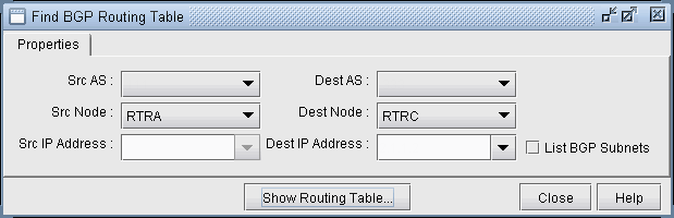
Choose a source node and a destination node (and/or destination IP address) from two different autonomous systems from the drop down lists and then click on the Show Routing Table button. Selecting the SrcAS and DestAS is not required but is only used to filter the Src Node and Dest Node lists. (The Dest AS will be ignored if it is in a different AS than the Destination IP Address entered.) Selecting a blank SrcAS and DestAS field can be done to retrieve back all source and destination nodes from the node drop down lists.
Note that different destination IP addresses may have different attributes and associated routing policies. The destination IP address can be directly entered or populated by first selecting the Dest Node. To load additional IP addresses at that node found in the BGP Subnet window into the drop down list (Network > Protocols > BGP > BGP Subnets...), check “List BGP Subnets.”
If you already know the IP address, you can skip selecting the matching Dest Node or Dest AS, which can be derived from the IP address. Note also that this destination IP address should either be included in one of the BGP subnets (see BGP Subnets for more information), or defined on the destination node.
Another method of choosing the source and destination nodes is to use the mouse and the Standard (not BGP) map. After selecting the Network > Protocols > BGP > BGP Routing Table function, move the mouse over the map. Notice that the arrow of the mouse turns into a cross hair. Click on the first node, which will be the source node. Move the cross hair to another node and click on it to specify the destination node. Then move to the Find BGP Routing Table window and click on the OK button.
Tip: To clearly see which nodes belong to which ASs from the map, go to the Standard map’s Filter menu and make sure that the box for Hide ASNodes/Links is unchecked. You might also use the map’s right-click menu’s Grouping>AutoGroup option and group your nodes by AS and go to the Subviews > AS menu to color the nodes by AS.
Troubleshooting: In some cases the BGP routing table search does not return any results. Make sure that the SrcAS and Dest AS are different. Additionally, check the EBGP neighbor relationships from the BGP map in Network > Maps > Maps (BGP View) to verify whether two routers can communicate using EBGP. Finally, check that the destination IP address is either assigned to the destination node, or a BGP subnet originated from that node.
The BGP Routing Table window shows all possible routes from the specified source node to the specified destination node/IP address. The fields shown on the window are:
Field | Description |
---|---|
Src IP Address | The IP address of the source node. |
Src Node | The name of the source node. |
Dest IP Address | The IP address of the destination node. |
Dest Node | The name of the destination node. |
Exit Src AS | This shows the router name and IP address for the last BGP speaker on the path before it exits the AS of the source node. |
BGP Next Hop | The router name and IP address of the BGP next hop. |
Mask | The corresponding mask of the destination IP address. |
Preference | This is not a BGP property, but is used to indicate the preferred BGP next hop chosen by the BGP route selection process when there is more than one possible path. Possible values are “Preferred”, “Blocked”, or blank. |
Weight | The weight attribute |
Local Preference | The local preference number. |
Med | The Multi-Exit Discriminator attribute |
AS Path | The AS path attribute, which consists of AS numbers of all ASs that the route traverses, the most recently traversed one displayed first. |
Community String | The Community Attribute |
Origin | The origin attribute indicates how a route was learned (e.g., IGP, EGP, or Incomplete) |
Distance | Total metric of the IGP route from the router to the Exit Src AS router |

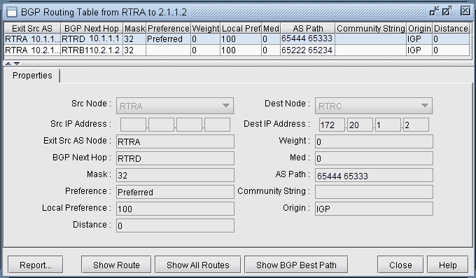
Highlight a BGP route entry and then click on the Show Route button to display the route on the standard map. Or select Show All Routes to display routes for all the BGP Routing Table entries displayed. Note that the gray line symbolizes the connection to the BGP next hop. Click “Show Path” to show the actual path that would be used.