ON THIS PAGE
Maintenance Events
Use the Maintenance option to schedule maintenance events for network elements, so you can perform updates or other configuration tasks. Maintenance events are planned failures at specific future dates and times. During a scheduled maintenance event, the selected elements are considered logically down, and the system reroutes the LSPs around those elements during the maintenance period. After the maintenance event is completed, the default behavior is that all LSPs that were affected by the event are reoptimized. There is an option that allows you to disable that reoptimization if you want to complete the maintenance event, but keep the paths in their rerouted condition.
NorthStar only attempts to reoptimize PCE-initiated and PCC-delegated LSPs (not PCC-controlled LSPs).
Maintenance events can also be created by NorthStar when the link packet loss threshold has been exceeded, triggering LSP rerouting. See LSP Routing Behavior for more information about LSP rerouting.
For information on system settings that can affect path computation before and after maintenance events, see Subscribers and System Settings.
Viewing Scheduled Maintenance Events
You can view scheduled maintenance events for network elements in the Maintenance tab of the network information table. In the network information table, the Node, Link, and Tunnel tabs are always displayed. Maintenance is one of the tabs you can optionally display. Click the plus sign (+) in the tabs heading bar and select Maintenance from the drop-down menu.
Table 1 describes the columns displayed in the Maintenance tab.
| Field | Description |
Name |
Name assigned to the scheduled maintenance event. The name specified for the maintenance event is also used to name the subfolder for reports in the Report Manager. Note:
The names of triggered maintenance events (created by NorthStar) indicate they were triggered by packet loss. |
Nodes |
Number of nodes scheduled for maintenance. |
Links |
Number of links scheduled for maintenance. |
SRLGs |
Number of SRLGs scheduled for maintenance. |
Start Time |
Start time for the maintenance event. |
End Time |
End time for the maintenance event. |
Estimated Duration |
Estimated duration for the maintenance event, which is calculated as the duration between the Start Time and End Time in the Maintenance Scheduler window. |
Owner |
Owner (creator) of the maintenance event. |
Operation Status |
Possible status conditions are:
|
Comment |
Comments entered when the event was added or modified. If a maintenance event was created as a result of a Network Maintenance task (Administration > Task Scheduler), the system adds a comment, “created by maintenance task”. See Creating Maintenance Events for Devices with the Overload Bit Set for information about this type of maintenance event. |
Auto Complete |
When selected, NorthStar automatically sets the event’s Operation Status to Completed at the specified End Time. Note:
For NorthStar-created maintenance events, this option is not available. NorthStar-created events require manual completion via the Modify Maintenance Event window. |
No LSP Reoptimization |
When selected, NorthStar does not automatically reoptimize LSPs when the event is completed. |
Node Names |
Nodes included in the event. |
Link Names |
Links included in the event. |
SRLG Names |
SRLGs included in the event. |
Adding a Maintenance Event
Add a new maintenance event by clicking the Maintenance tab in the network information table, and clicking Add at the bottom of the table. The Add Maintenance Event window is displayed as shown in Figure 1.
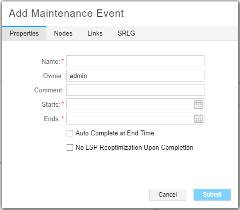
Table 2 describes the data entry fields available in the Properties tab. A red asterisk denotes a required field.
Field |
Description |
|---|---|
Name |
Required. Enter a name for the maintenance event. |
Owner |
This field auto-populates with the user that is scheduling the maintenance event. |
Comment |
Enter a comment for the maintenance event. |
Starts |
Required. Click the calendar icon to display a monthly calender from which you can select the year, month, day, and time. |
Ends |
Required. Click the calendar icon to display a monthly calender from which you can select the year, month, day, and time. |
Auto Complete at End Time |
Select the Auto Complete at End Time check box to automatically complete the maintenance event (bring the elements back up) at the specified end time. If the check box is not selected, you must manually complete the maintenance event after it finishes. Note:
To manually complete an event, select it in the network information table, click Modify, and use the drop-down menu in the Status field to select Completed. When a maintenance event is completed, it triggers NorthStar to bring the maintenance elements back to an Up state, ready for path reoptimization. The affected LSPs are then rerouted to optimal paths unless you selected No LSP Reoptimization Upon Completion. |
No LSP Reoptimization Upon Completion |
The default behavior is for the system to reoptimize those LSPs that were affected by the maintenance event when the maintenance event is completed. When you check the No LSP Reoptimization Upon Completion option, that behavior is disabled. This allows you to use a maintenance event to temporarily disable a link in NorthStar. You can reoptimize all LSPs by navigating to Applications > Path Optimization. You can reoptimize specific LSPs by selecting them in the Tunnel tab of the network information table, right-clicking, and selecting Trigger LSP Optimization from the drop-down menu. You can also right-click on links in the Link tab to reoptimize LSPs on those links. |
Use the Nodes, Links, and SRLG tabs to select the elements that are to be included in the maintenance event. All three of these tabs are structured in the same way. Figure 2 shows an example.
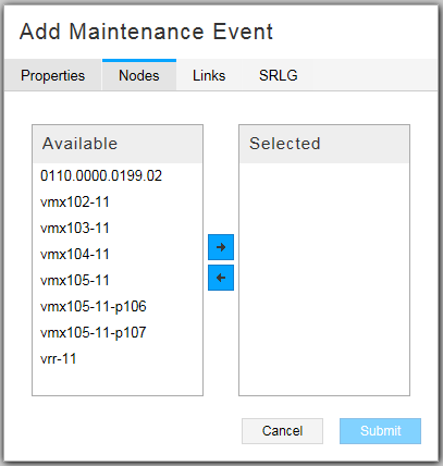
Select elements in the Available column and click the right arrow to move them to the Selected column. Click the left arrow to deselect elements. Click Submit when finished. The new maintenance event appears in the network information table at the bottom of the Topology view.
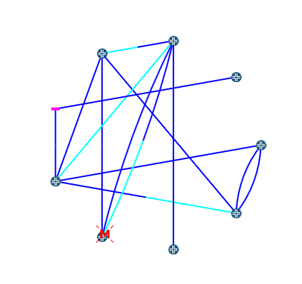
When an element (node, link, or SRLG) is undergoing a maintenance event, it appears on the topology map with an M (for maintenance) through the element. Figure 3 shows an example.
NorthStar-Created Maintenance Events
In the Maintenance tab of the network information table, you might also see maintenance events created by NorthStar in response to packet loss on a link. These events include just one link per event, and they are named to indicate that they were created in response to packet loss. The corresponding link in the topology map displays with the M through it that indicates the link is logically down due to a maintenance event.
These events start immediately when the link packet loss threshold is exceeded, and the end time is set for one hour later. Because this type of maintenance event requires manual completion, the end time is not significant.
These events do not automatically complete because there is no way for NorthStar to know when troubleshooting efforts have been successful and the link has been restored to stability. Therefore, you must manually complete these events using the Modify Maintenance Event window.
Modifying Maintenance Events
To modify a planned maintenance event, select the maintenance event row in the Maintenance tab of the network information table and click Modify at the bottom of the table. The Modify Maintenance Event window is displayed where you can change the parameters, schedule, or status. Figure 4shows the Properties tab in the Modify window.
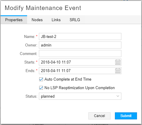
See Table 2 and Table 1 for descriptions of these fields and possible values.
When you are finished updating the fields, click OK. The updates you made are reflected in the network information table.
Canceling and Deleting Maintenance Events
When you cancel a maintenance event, it remains in the Maintenance tab of the network information table, with an operation status of Cancelled. When you delete an event, it is completely removed from the network information table. You might want to cancel an event rather than delete it if you think you will reactivate it later, possibly with modifications, or if you need it for tracking purposes.
You cannot delete a maintenance event that is in progress. You can, however, cancel one.
To cancel a maintenance event, select the event row in the Maintenance tab of the network information table and click Modify at the bottom of the table. Use the drop-down menu in the Status field to select Cancelled.
To delete a maintenance event, you can select the event row and click Delete at the bottom of the table. Alternatively, you can select the event row and click Modify at the bottom of the table. Use the drop-down menu in the Status field to select Deleted. With either method, the row is removed from the table.
Creating Maintenance Events for Devices with the Overload Bit Set
When a device has the overload bit set, it might be at risk of going down. Putting such devices under maintenance and routing traffic around them until the issue is resolved is a preventative measure. Rather than monitoring for the overload bit manually, NorthStar supports automatically creating and completing maintenance events for devices that have the overload bit set. NorthStar discovers the overload bit setting via either NTAD or BMP.
Not all Junos OS releases set the overload bit properly when sending node advertisement to NorthStar. For example, the Junos VM bundled with NorthStar Release 5.0 does not support setting the overload bit. If you want to use this feature with NorthStar Release 5.0 and the bundled JunosVM, you can use BMP instead of NTAD.
To set up automatic creation and completion of an overload bit maintenance event, you create a Network Maintenance task in the Task Scheduler (Administration > Task Scheduler), and schedule it to recur at regular intervals.
In the Task Scheduler, click Add to bring up the Create New Task window. Enter a name for the task and use the Task Type drop-down menu to select Network Maintenance. Click Next to proceed to the options and conditions window shown in Figure 5.
Figure 5: Network Maintenance Task, Task Options Tab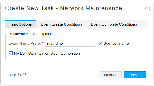
On the Task Options tab, Event Name Prefix is a required field. NorthStar uses the prefix in the naming of the maintenance event created by the task. The prefix is followed by a timestamp to ensure the uniqueness of the event name. You can either enter a prefix or you can select to use the name of the task as the prefix.
Click the No LSP Optimization Upon Completion check box if you don’t want NorthStar to automatically reoptimize LSPs when the event is completed.
The Event Create Conditions and Event Complete Conditions tabs are for specifying what should trigger the creation and completion of the maintenance event.
In the Event Create Conditions tab, highlight elements in the Available column and click the right arrow to move them into the Selected column. As of NorthStar Controller Release 5.0, the only available create condition is Node.
Once Node has been moved to the Selected column, the Attributes table displays in the lower part of the window. Click the plus sign (+) to add a property row and then click in the property row Name field to display the drop-down menu arrow. From the drop-down menu, select the create condition. As of NorthStar Release 5.0, the only available create condition is overloadBit. In the Value column, use the drop-down menu to select the value of True for the overloadBit create condition.
Note:For other create conditions available in future releases, False might be the appropriate selection.
Figure 6 shows the Event Create Conditions tab with the Attributes table displayed.
Figure 6: Network Maintenance Task, Event Create Conditions Tab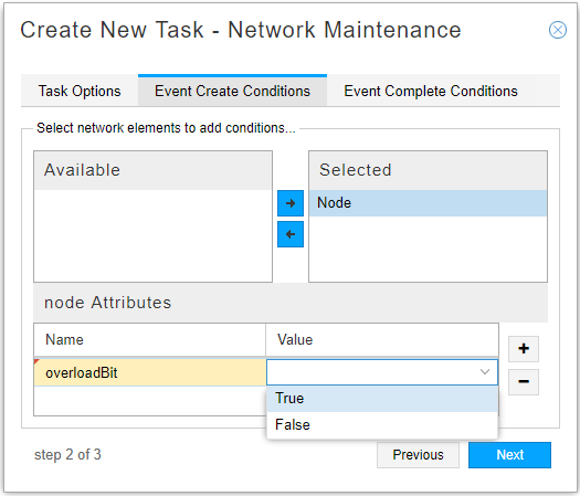
There are sorting and column selection tools available in the Attributes table headings. These will be more useful later, when additional create conditions are implemented.
The Event Complete Conditions tab fields work the same way as the Event Create Conditions tab fields. Select Node and move it from Available to Selected. Click the plus sign (+) beside the Attributes table, click in the Name field of the new row, and use the drop-down menu to select overloadBit. In the Value field, select False. Click Next to proceed to the scheduling window.
In the scheduling window, specify when the task should start and how often it should repeat. Click Submit. The task appears in the list of Task Scheduler tasks. See Introduction to the Task Scheduler for information about monitoring the progress of scheduled tasks.
Every time the task runs, it first checks the complete condition for the maintenance event created by the task. If all the elements included in the maintenance task satisfy the complete condition (overloadBit = false, for example), it completes the maintenance event. Next, it looks for elements that match the create conditions (overloadBit = true, for example). If it finds some, it creates a new maintenance event that includes those elements.
Just as for other maintenance events, the “M” symbol marks the affected nodes on the topology map. In the Maintenance tab of the network information table, the maintenance event displays the comment “created by maintenance task” in the Comment column.
This type of maintenance event completes when the included nodes no longer have the overload bit set, but the event will not automatically be deleted. You can manually delete the completed event from the Maintenance tab of the network information table.
Simulating Maintenance Events
You can run scheduled maintenance event simulations to test the resilience of your network. Network simulation is based on the current network state for the selected maintenance events at the time the simulation is initiated. Simulation does not simulate the maintenance event for a future network state or simulate elements from other concurrent maintenance events. You can run network simulations based on elements selected for a maintenance event, with the option to include exhaustive failure testing.
To access this function, right-click in the maintenance event row in the network information table and select Simulate.
The Maintenance Event Simulation window, as shown in Figure 7, displays the nodes, links, and SRLGs you selected to include in the event.
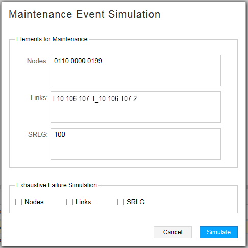
The Exhaustive Failure Simulation section at the bottom of the window is optional. It provides check boxes for selecting the element types you want to include in an exhaustive failure simulation. If you do not perform an exhaustive failure simulation (all check boxes under Exhaustive Failure Simulation are cleared), all the nodes, links, and SRLGs selected for the maintenance event fail concurrently. In Figure 7, for example, node 0110.0000.0199, link L10.106.107.1_.10.106.107.2, and SRLG 100 would all fail at the same time.
Using this same example, but with Nodes selected under Exhaustive Failure Simulation, the simulation still fails all the maintenance event elements concurrently, but simultaneously fails each of the other nodes in the topology, one at a time. If you select multiple element types for exhaustive failure simulation, all possible combinations involving those elements are tested. The subsequent report reflects peak values based on the worst performing combination.
Whether or not you select exhaustive failure, click Simulate to perform the simulation and generate reports.
Viewing Failure Simulation Reports
When a simulation completes, the Reports menu is displayed, showing a list of the newly generated reports for the simulation, grouped into a folder with the same name as the maintenance event. You can also view the reports any time by navigating to Applications>Reports.
The following reports are available for each maintenance event simulation:
RSVP Link Utilization Changes: Shows changes to the tunnel paths, number of hops, path cost, and delay.
Peak Simulation Stat Summary: Shows the summary view of the count, bandwidth, and hops of the impacted and failed tunnels.
Peak Simulation Tunnel Failure Info: Lists the tunnels that were unable to reroute and the causing events during exhaustive failure simulation.
LSP Path Changes: Shows changes to the tunnel paths, number of hops, path cost, and delay.
Link Peak Utilization: For each link, this report shows the peak utilization encountered from one or more elements that failed.
Link Oversubscription Stat Summary: Lists the links that reached over 100% utilization during exhaustive failure simulation.
Physical Interface Peak Utilization Report: Physical interfaces report with normal utilization, the worst utilization, and the causing events during exhaustive failure simulation.
Maintenance Event Simulation Report: Link utilization and LSP routing changes during failure simulation caused by maintenance events.
Path Delay Information Report: Shows the worst path delay and distance experience by each tunnel and the associated failure event that caused the worst-case scenario.
