- play_arrow Introduction
- play_arrow Router Data Extraction
- play_arrow Routing Protocols
- play_arrow Equal Cost Multiple Paths
- play_arrow Static Routes
- play_arrow Policy-Based Routes
- play_arrow Border Gateway Protocol
- NorthStar Planner Border Gateway Protocol Overview
- Border Gateway Protocol Recommended Instructions
- BGP Data Extraction
- BGP Reports
- BGP Options
- BGP Map
- BGP Live Status Check
- BGP Routing Table
- BGP Routes Analysis
- BGP Information at a Node
- BGP Neighbor
- Apply, Modify, or Add BGP Polices
- BGP Subnets
- Getipconf Usage Notes
- BGP Report
- play_arrow Virtual Private Networks
- NorthStar Planner Virtual Private Networks Overview
- Importing VPN Information from Router Configuration Files
- Viewing the Integrity Checks Reports
- Accessing VPN Summary Information
- Accessing Detailed Information for a Particular VPN
- VPN Topology View
- Route-Target Export/Import Relationships
- Additional Methods to Access VPN Information
- VPN Path Tracing
- VPN Design and Modeling Using the VPN Wizard
- L3 (Layer 3) VPN
- L3 Hub-and-Spoke VPN
- L2M (Layer2-Martini) VPN
- L2K (Layer2-Kompella) VPN
- VPLS-BGP VPN (for Juniper)
- VPLS-LDP VPN
- L2CCC (Circuit Cross-Connect) VPN
- Inter-AS VPN
- Forming VPN Customer Groups
- Deleting or Renaming VPNs
- VPN Configlet Generation
- Adding Traffic Demands in a VPN
- VPN Traffic Generation
- VPN-Related Reports
- VPN Monitoring and Diagnostics
- play_arrow GRE Tunnels
- play_arrow Multicast
- NorthStar Planner Multicast Overview
- NorthStar Planner Recommended Multicast Instructions
- Creating Multicast Groups
- Creating Multicast Demands
- Viewing Multicast Demands in the Network
- Comparing Multicast with Unicast
- Multicast SPT Threshold
- Multicast Reports
- Multicast Simulation
- Collecting Multicast Path Data from Live Network
- Importing Multicast Path Data
- Multicast Data Processing
- Viewing Multicast Trees
- play_arrow Class of Service
- NorthStar Planner Class of Service Overview
- NorthStar Planner Recommended CoS Instructions
- The QoS Manager
- Define Class Maps
- Create Policies for Classes
- Attach Policies to Interfaces
- Adding Traffic Inputs
- Using the Text Editor
- Reporting Module
- IP Flow Information
- Link information
- Traffic Load Analysis
- Traffic Load by Policy Class
- CoS Alias File
- Bblink File
- Policymap File
- Demand File
- Traffic Load File
- play_arrow Routing Instances
- play_arrow LSP Tunnels
- NorthStar Planner LSP Tunnels Overview
- Viewing Tunnel Info
- Viewing Primary and Backup Paths
- Viewing Tunnel Utilization Information from the Topology Map
- Viewing Tunnels Through a Link
- Viewing Demands Through a Tunnel
- Viewing Link Attributes/Admin-Group
- Viewing Tunnel-Related Reports
- Adding Primary Tunnels
- Adding Multiple Tunnels
- Mark MPLS-Enabled on Links Along Path
- Modifying Tunnels
- Path Configuration
- Specifying a Dynamic Path
- Specifying Alternate Routes, Secondary and Backup Tunnels
- Adding and Assigning Tunnel ID Groups
- Making Specifications for Fast Reroute
- Specifying Tunnel Constraints (Affinity/Mask or Include/Exclude)
- Adding One-Hop Tunnels
- Tunnel Layer and Layer 3 Routing Interaction
- play_arrow Optimizing Tunnel Paths
- play_arrow Tunnel Sizing and Demand Sizing
- play_arrow Tunnel Path Design
- Tunnel Path Design Overview
- Tunnel Path Design Instructions
- Designing Tunnel Paths Overview
- Backup Path Configuration Options
- Default Diversity Level
- Evaluate/Tune Options
- Advanced Options
- Viewing Design Results
- Tunnel Modifications
- Exporting and Importing Diverse Group Definitions
- Advanced Path Modification
- play_arrow Inter-Area MPLS-TE
- play_arrow Point-to-Multipoint (P2MP) Traffic Engineering
- NorthStar Planner P2MP Traffic Engineering Overview
- Point-to-Multipoint Traffic Engineering Instructions
- Import a Network That Already has Configured P2MP LSP Tunnels
- Examine the P2MP LSP Tunnels
- Create P2MP LSP Tunnels and Generate Corresponding LSP Configlets
- Examine P2MP LSP Tunnel Link Utilization
- Perform Failure Simulation and Assess the Impact
- play_arrow Diverse Multicast Tree Design
- Diverse Multicast Tree Design Overview
- Diverse Multicast Tree Instructions
- Open a Network That Already Has a Multicast Tree
- Set the Two P2MP Trees of Interest to be in the Same Diversity Group
- Using the Multicast Tree Design Feature to Design Diverse Multicast Trees
- Using the Multicast Tree Design Feature
- play_arrow DiffServ Traffic Engineering Tunnels
- DiffServ Traffic Engineering Tunnels Overview
- Using DS-TE LSP
- Hardware Support for DS-TE LSP
- NorthStar Planner Support for DS-TE LSP
- Configuring the Bandwidth Model and Default Bandwidth Partitions
- Forwarding Class to Class Type Mapping
- Link Bandwidth Reservation
- Creating a New Multi-Class or Single-Class LSP
- Configuring a DiffServ-Aware LSP
- Tunnel Routing
- Link Utilization Analysis
- play_arrow Fast Reroute
- NorthStar Planner Fast Reroute Overview
- Fast Reroute Supported Vendors
- Import Config and Tunnel Path
- Viewing the FRR Configuration
- Viewing FRR Backup Tunnels
- Viewing Primary Tunnels Protected by a Bypass Tunnel
- Modifying Tunnels to Request FRR Protection
- Modifying Links to Configure Multiple Bypasses (Juniper only)
- Modifying Links to Trigger FRR Backup Tunnel Creation (Cisco)
- FRR Design
- FRR Auto Design
- FRR Tuning
- Viewing Created Backup Tunnels
- Generating LSP Configlets for FRR Backup Tunnels
- Failure Simulation—Testing the FRR Backup Tunnels
- Exhaustive Failure
- Link, Site and Facility Diverse Paths
- play_arrow Cisco Auto-Tunnels
- play_arrow Integrity Check Report
- play_arrow Compliance Assessment Tool
- Compliance Assessment Tool Overview
- Using The Compliance Assessment Tool
- CAT Testcase Design
- Creating a New Project
- Loading the Configuration Files
- Creating Conformance Templates
- Reviewing and Saving the Template
- Saving and Loading Projects
- Run Compliance Assessment Check
- Compliance Assessment Results
- Publishing Templates
- Running External Compliance Assessment Scripts
- Scheduling Configuration Checking in Task Manager
- Building Templates
- Special Built-In Functions
- Paragon Planner Keywords For Use Within a Rule
- More on Regular Expressions
- IP Manipulation
- play_arrow Virtual Local Area Networks
- play_arrow Overhead Calculation
- play_arrow Router Reference
Viewing the Results
Trafficload
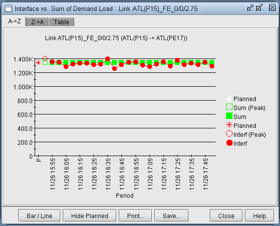
If the period “All” was designed for, then not only will the demands be updated, but also the trafficload file which includes the designed bandwidth of the demand for multiple periods. The T-Solve window will only display the results for the final period. However, the per-period results can be viewed per link after the design by right-clicking the link on the map and selecting Traffic Load > Interface vs Demand. Select Bar/Line to view the chart as a line chart. This chart will show how well the utilization based on the designed trafficload bandwidth matches with the actual interface load.

Save the network to a new directory using File > Save Network... Navigate to this directory in the File Manager and open the designed trafficload file to see the bandwidths designed for each period.
Console
Intermediate results will be displayed in the console. In each successive iteration, the program attempts to minimize the cost function, which is based on the linkDiff + shape weight * shapeDiff, where the linkDiff is a function of the sum of the differences between measured interface traffic and an interface’s total demand bandwidth over the sum of the link bandwidths.
The following information is also indicated to provide warnings regarding incomplete data. The links indicated below will not be considered into the cost function. These should be checked to see if that is the desired behavior or not, or if additional information can be supplied.
#link_interface without traffic and demands=n : Indicates number of links with no seed demands nor measured interface traffic.
#link_interface without traffic=n : Indicates number of links with seed demands routed over it, but no measured interface traffic.
#link_interface without demands=n : Indicates number of links with measured interface traffic, but without seed demands routed over it. If these are links that are important, then it may be a good idea to add the appropriate flow(s) that goes through this link into the demand file. In some cases, however, you may not worry about the link, in which case it can be ignored. For example, this might be the case if you are only concerned about running designs and simulations for Area 0 traffic and link loading, but this is a link in a different area.
Reports
After the iterations are completed, the following output files will be saved to the server:
TMLINK.runcode : The Tomogravity Link Traffic Comparison Report provides information (per link) regarding differences between measured interface traffic and the interface’s total demand load (see Links Tab)
TMShape.runcode : The Tomgravity Demand Traffic Shape Report provides information regarding the shape matrix and the traffic matrix.
TMPATH.runcode : Provides Path Placement and bandwidth Information
TMLOAD.runcode : The T-solve Demand Bandwidth vs Demand Load Comparison Report provides information (per flow) about the difference between model demand bandwidth and measured demand bandwidth from the trafficload file
Once complete, select Network > Elements > Demands to view the changed demand bandwidths assigned by the Traffic Matrix Solver.
Summary Tab
Click the Summary tab to see a summary of the statistics from the links tab.
overallFit : Sum of the absolute differences between the measured interface traffic and interface’s total demand load divided by the sum of the measured traffic plus geometric mean of the measured and modeled traffic. Note that the results are independent of the link bandwidth.
formula : overallFit = |measured traffic - demand| / [measured traffic + SQRT (measured traffic * modeled traffic)]
For example, a 10G link between two nodes with measured interface traffic 5G for both interfaces on that link and 8G bidirectional demand over the link. In this example the absolute difference is |5G - 8G| = 3G. The geometric mean is SQRT(5*8) = 6.325. Thus the overallFit = absolute difference / (measured traffic + geometric mean) = 3/(5 + 6.325) = 0.2649 = 26.49%.
ShapeError : The shaping error is based on a comparison the shaping matrix derived from normalizing the seed demands’ bandwidth matrix, against the shaping matrix derived from normalizing the demands’ new bandwidth matrix.
WorstLinkDiff : Indicates the largest difference between the measured and model utilization percentage, i.e., the highest value for Abs Diff Util % in the Links tab.
When evaluating the fit of the new traffic matrix to the interface traffic file, the linkDiff provides an averaged difference, and the worst link diff provides the worst case difference for a particular link. Ideally, these two numbers should be as close to zero as possible.
Links Tab
Select the Links tab of the T-Solve window.

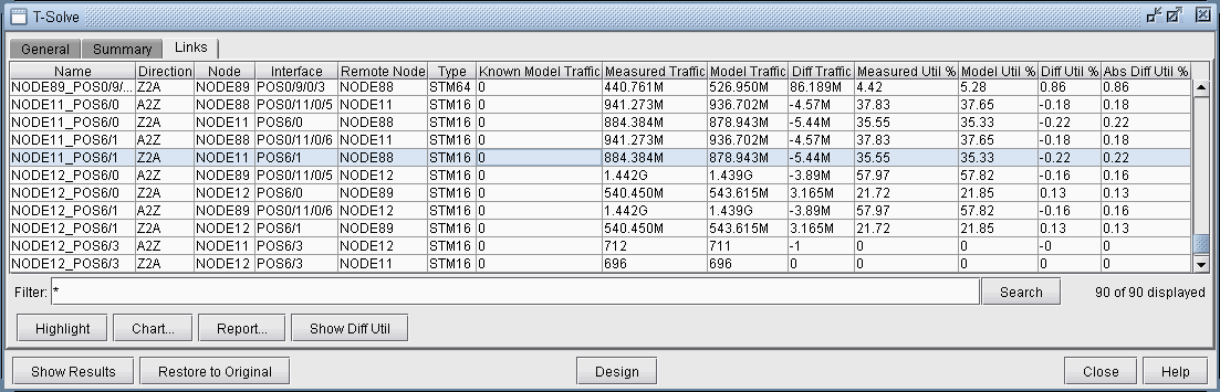
Here, you can view statistics comparing the original measured interface traffic file (Measured Traffic and Measured Util %) with the traffic load and utilizations computed based on the set of end-to-end demands (Model Traffic and Model Util %).
Name : Link’s name
Direction : A2Z or Z2A direction of the link
Node,Interface : The node and interface corresponding to the given direction on the link
Remote Node : The other end node of the link
Type : The link’s Trunk Type
Known Model Traffic : Traffic load on the link based on measured flow bandwidth (based on the trafficload file)
Measured Traffic : Traffic load on the link according to measured interface traffic file (based on the egress/ingress files)
Diff Traffic : The difference between Model Traffic and Measured Interface Traffic. Note that the values -1, -2, -3, and -4 have special meanings here: “-4” means that there is measured interface traffic, but model traffic is 0, “-3” means that there is model traffic, but measured interface traffic is 0, “-2” means that there is model traffic but measured traffic is missing, and “-1” means the model traffic is 0, but measured interface traffic is missing.
Measured Util % : Percentage Utilization of the link according to measured interface traffic file (based on the egress/ingress files)
Model Util % : Percentage Utilization of the link according to the sum of bandwidth of demands over the link (based on the demand file0
Diff Util % : Model Util % - Measured Util %
Abs Diff Util % : The absolute value of Diff Util % (This number will always be positive)