Specifying a Dynamic Path
Configuring a Dynamic Route Between Source and Destination
To add a tunnel with a dynamic route between two nodes, after you have configured the source, destination, bandwidth, priority and preempt fields, simply click the “Add” button.
The word “Dynamic” should be displayed under the pathname column.
Configuring a Loose Route
To add in a loose route, double-click the cell under the Configured Route and type in a route. Where the route is “loose”, enter in two asterisks as the delimiter. For example, CHI-DAL**HOU**LAX**ATL would be an example of a loose route, where the only fixed portion is the path from Chicago (CHI) to Dallas (DAL). Since the exact route is not specified, it will be up to the hardware to choose a route going from DAL to HOU, HOU to LAX, and LAX to ATL.
Alternatively, you can specify a Loose Route through the Tunnel Path Selection window by right-clicking the row and selecting Edit Route. In the Tunnel Path Selection window, select the Loose Route radio button. You will then have a wider array of options to choose from when you are adding nodes or links to your route. Note that the nodes should still be in sequential order. When you have added the destination router, the OK button will be enabled to allow you to finish adding the loose route.
Configuring an Explicit Route Based On Current Route
To cause the Current Route to be set as the Configured Route, select “Add” “Config” in the Path Config. Options explained in Path Config Options on page 252.
Excluding Network Elements from a Path (for Cisco Routers)
You can specify dynamic routes that avoid particular nodes or links. However, for accurate modeling of your network, you should only choose this option if your hardware supports this feature. Cisco routers implement this with the “exclude-address” command.
To choose nodes or links to exclude from the map, select Click links/nodes on map, then right-click in table from the To choose paths: menu.
Next, click on the network elements you want to exclude from the route to highlight them. Note that you can hold down <CTRL> or <SHIFT> keys while clicking network elements to select more than one.
After you have selected the elements to exclude, right-click on the row of the table that you want to modify and select Use Map Sel’n as Excluded (Sel’n is an abbreviation for Selection). This will cause a statement to be entered into the Configured Route field like the following: EXCLUDE-NODEA-LINK1-LINK8-LINK14.
Alternatively, you can double-click the Configured Route field and type in a string starting with “EXCLUDE” and containing the IDs of the elements that are to be excluded separated by dashes ‘-’ (one dash separates each element). After you have entered in some text, click on a different table cell in order to turn the editing mode off.
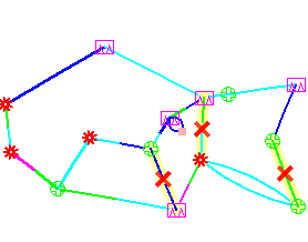
To visualize which elements you are excluding in a particular row, click on a table cell in that row that you are not editing. Select Show Route to view the excluded elements on the Map, which will be marked with an X as shown in Figure 1.
Figure 1: Marked Elements to Avoid in Route
