Simulation
When you click the menu icon (horizontal bars) in the upper left corner of the Planner and select Simulation, the Simulation tool opens in the main window (a network must be open for this option to be available). The Simulation tool allows you to run failure analysis using path provisioning that simulates the hardware’s implementation of bandwidth allocation and demand routing on the existing topology. This tool walks you through creating a simulation, step by step.
After selecting at least one element in Step 1, you are not restricted to progressing through these steps in order. You can click on any Step number directly to go backward and forward rather than using the Next or Back buttons.
Using this tool, you can design a simulation that uses a single, double, or triple exhaustive failure combination, using network element types of your choice.
NorthStar web UI Planner runs modeling and simulation in whichever layer (Tunnel/Layer 2 or Layer 3) you have selected and that is displayed in the top menu bar.
An exhaustive single failure simulation fails all network elements of a given type, one at a time. For example, an exhaustive node failure fails every node in the network, one at a time. For an exhaustive double failure simulation, two elements are failed at once. For example, if you select Node and Link for a Double exhaustive failure, the simulation would then fail all node and node, node and link, and link and link combinations. An exhaustive triple failure fails three elements at once.
The tool also allows you to select a routing method to use for the simulation, either Normal, Fast Reroute (FRR), or both (the default). Fast Reroute is a mechanism that can be used to protect MPLS traffic engineering LSP tunnels in the event of node or link failures. It accomplishes this with SONET-like restoration times by locally repairing the LSPs at the point of failure, using backup tunnels that bypass the failure while waiting for the head-end routers to establish a new LSP. The short restoration times are especially desirable for real-time applications such as voice over IP, which often cannot tolerate high delays. “Normal” routing method means “without FRR.”
To design and execute a simulation, use the following procedure.
In Step 1, shown in Figure 1, select the exhaustive failure combination from the drop-down menu (Single, Double, or Triple) and click the check boxes corresponding to the network elements to be included in the simulation.
Figure 1: Simulation, Step 1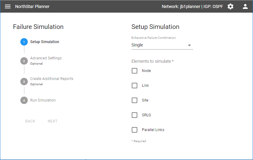
The default exhaustive failure combination is Single. No network elements are selected by default. You must select at least one network element type. When the form is complete, click Next.
In Step 2, shown in Figure 2, you can accept the default routing method (Normal and FRR) or use the drop-down menu to select an alternative (Normal alone or FRR alone).
Figure 2: Simulation, Step 2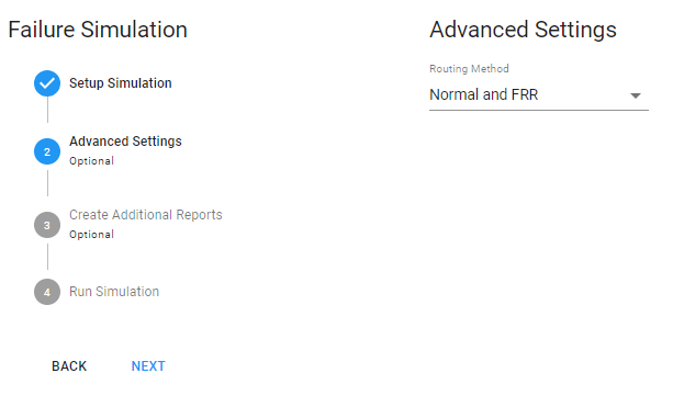
Click Next.
In Step 3, shown in Figure 3, click the check boxes for any additional reports you would like generated.
Figure 3: Simulation, Step 3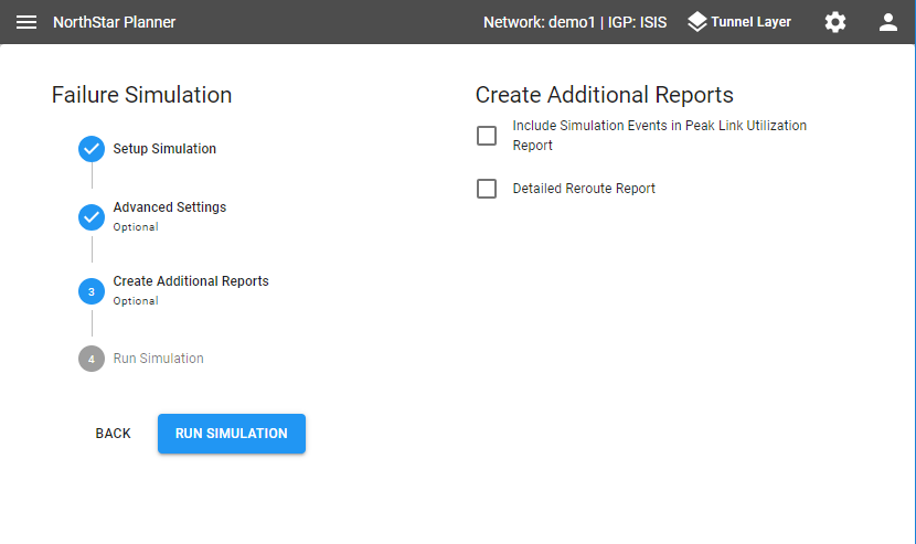
Click Run Simulation.
A success message indicates the simulation was executed, as shown in Figure 4.
Figure 4: Simulation, Step 4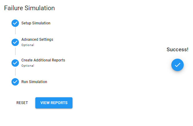
Click View Reports to go to the Report Manager where you can access all the simulation reports that were generated. Click Reset to begin another simulation.
In the Report Manager, simulation reports are overwritten by the next simulation, so be sure to use the download tool (down arrow icon in the bottom tool bar) to download any reports you want to keep. The Report Manager is fully documented in Report Manager.