Understanding the EPE Planner Application
Overview
Egress Peer Engineering (EPE) is the process by which a network operator directs traffic demands exiting their network to a peer operator network in the most cost effective way. Various factors influence the effectiveness and cost of an EPE plan, including:
The cost of transporting traffic demands across the operator’s network
The load on the egress peer links
The cost of using egress peer links
The cost to the peer operator to forward traffic to its ultimate destination
The NorthStar EPE Planner application is built on this EPE functionality to allow you to formulate plans that minimize the cost of traffic destined for peers. The EPE planner is bundled with the NorthStar Controller/Planner, and you install it in the same installation process.
You launch and operate the EPE Planner application through the NorthStar Controller web UI, where you can plan how to steer traffic into tunnels, taking internal transit, external transit, and peering costs into consideration, and generally manage the EPE planning and execution workflow.
You work on “projects” which are, essentially, planning sessions. A session begins with a “current plan”, represented by a snapshot of the live network. From there, you formulate plan changes, along with step-by-step execution plans to make the proposed changes safely in the network. Ultimately, you can execute the plans in the live network. Figure 1 illustrates the general work flow.
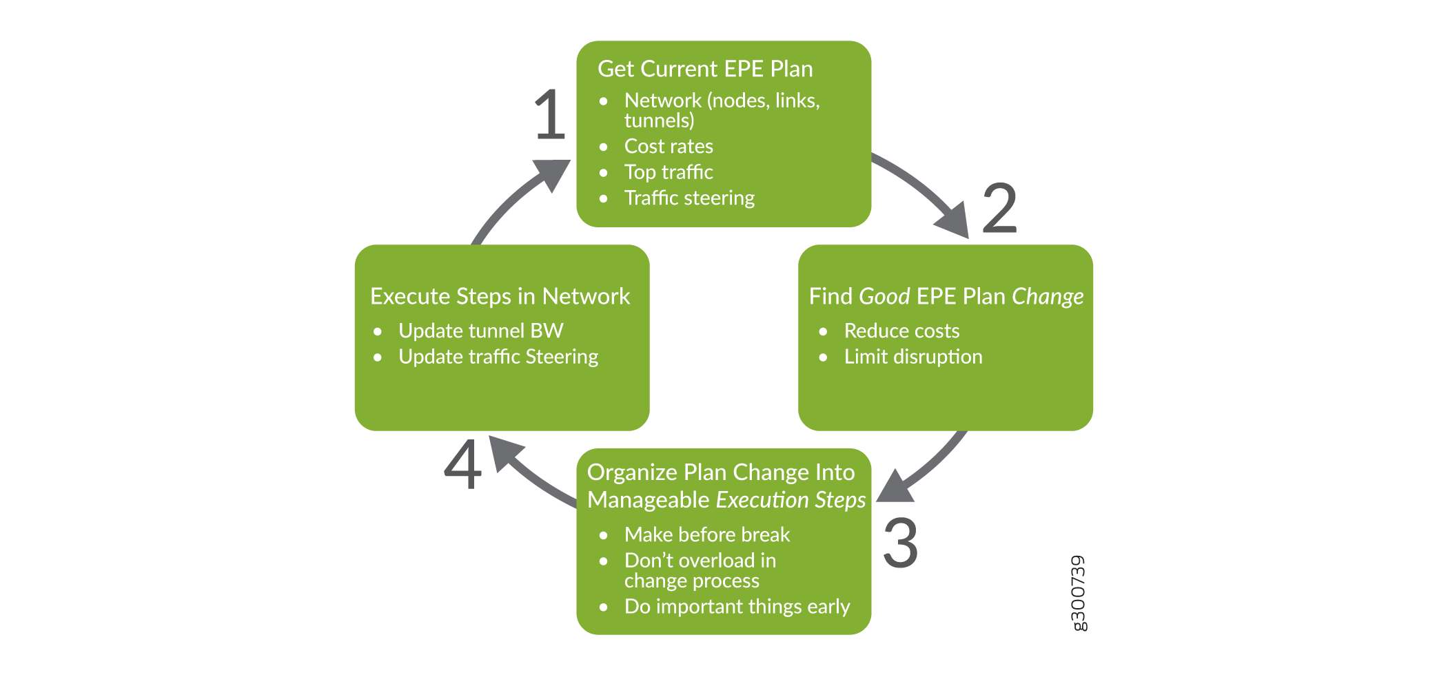
The EPE Planner allows you to monitor the performance of the EPE plan in your network as the traffic, cost functions, and other network conditions change over time.
If monitoring reveals that the EPE plan performance is degrading, you can use the EPE Planner as a tool to propose new plans that could get the performance back on track. You can evaluate proposed plans before actually making any change.
Before implementing a plan in the network, use the EPE Planner to organize the proposed new plan into a sequence of safe and manageable execution steps.
Once you have constructed an execution plan, the EPE Planner can automatically carry out the sequence of steps, making the changes in the network required to move to the new plan. You can use the EPE planner to monitor the progress of these changes.
There is an EPE application microservice that provides the EPE planning and plan execution functionality via the NorthStar REST API. Internally, the “EPEPlanAndExecute” interface is provided by a project repository. Each project within the repository contains a snapshot of the EPE network and current EPE plan, as well as a set of proposed plan changes from the current plan to a new (better) plan. The EPE network and current plan are instantiated from information available in the NorthStar REST API. The network is derived from the LSPs, nodes, and links. The current plan is derived from the demand-LSP bindings in the network and evaluated according to a cost model. The NorthStar REST API has EPE properties for LSPs, nodes, and links that facilitate the EPE plan costing. New plans are “better” in the sense that they evaluate to a lower cost according to the cost model.
In NorthStar, traffic is known as a “demand” (short for “traffic demand”), and traffic steering is implemented by binding a demand to an LSP. Hence the term, “demand-LSP bindings”.
A plan change can have an execution plan which is a way to safely apply the plan change in the network by changing LSP bandwidth and demand-LSP bindings via the NorthStar REST API. An execution plan consists of a sequence of execution plan steps that implement the plan change. The goal is to implement the plan change in a safe way, without unduly increasing the cost at any intermediate step, or causing other drastic fluctuations.
Figure 2 illustrates a top level model of the EPE Planner application, showing the basic concepts just described.
Representations like this are examples of class diagrams using Unified Modeling Language (UML). There are many online references describing UML notation to which you can refer if you are not familiar with it.
We use UML in the EPE Planner documentation because it is a succinct way to illustrate the system’s operations and the relationships between objects.
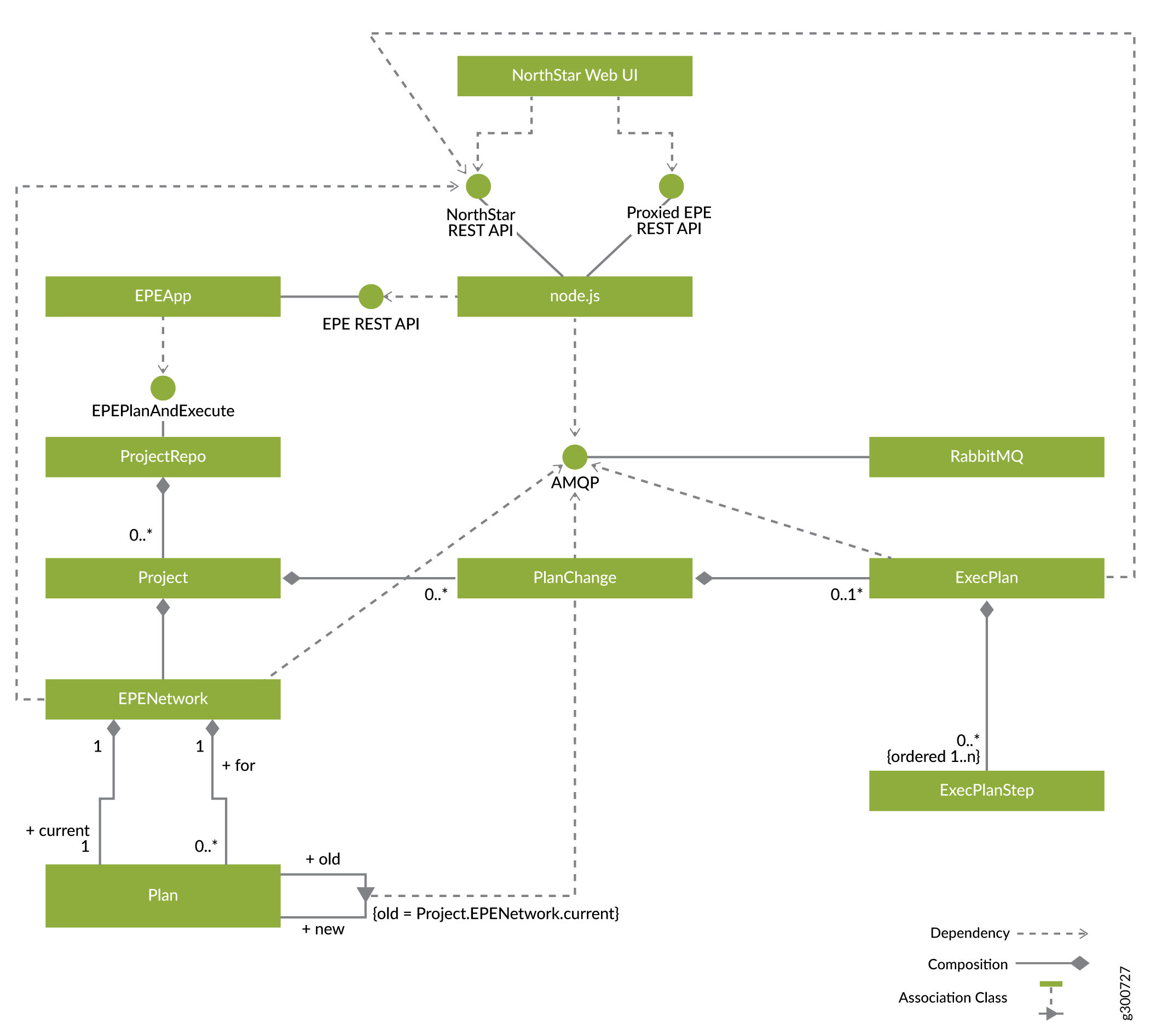
The EPE REST API is proxied by NorthStar’s node.js to become a new endpoint in the NorthStar REST API. There are three types of long-running operations for which asynchronous progress notifications are available:
Loading the network snapshot
Searching for plan changes optimizing the cost
Executing a plan change
These progress notifications are published to NorthStar’s RabbitMQ via AMQP, and node.js subscribes to them. Node.js handles them as socket.io notifications as it does with other NorthStar REST API notifications.
The EPE Network
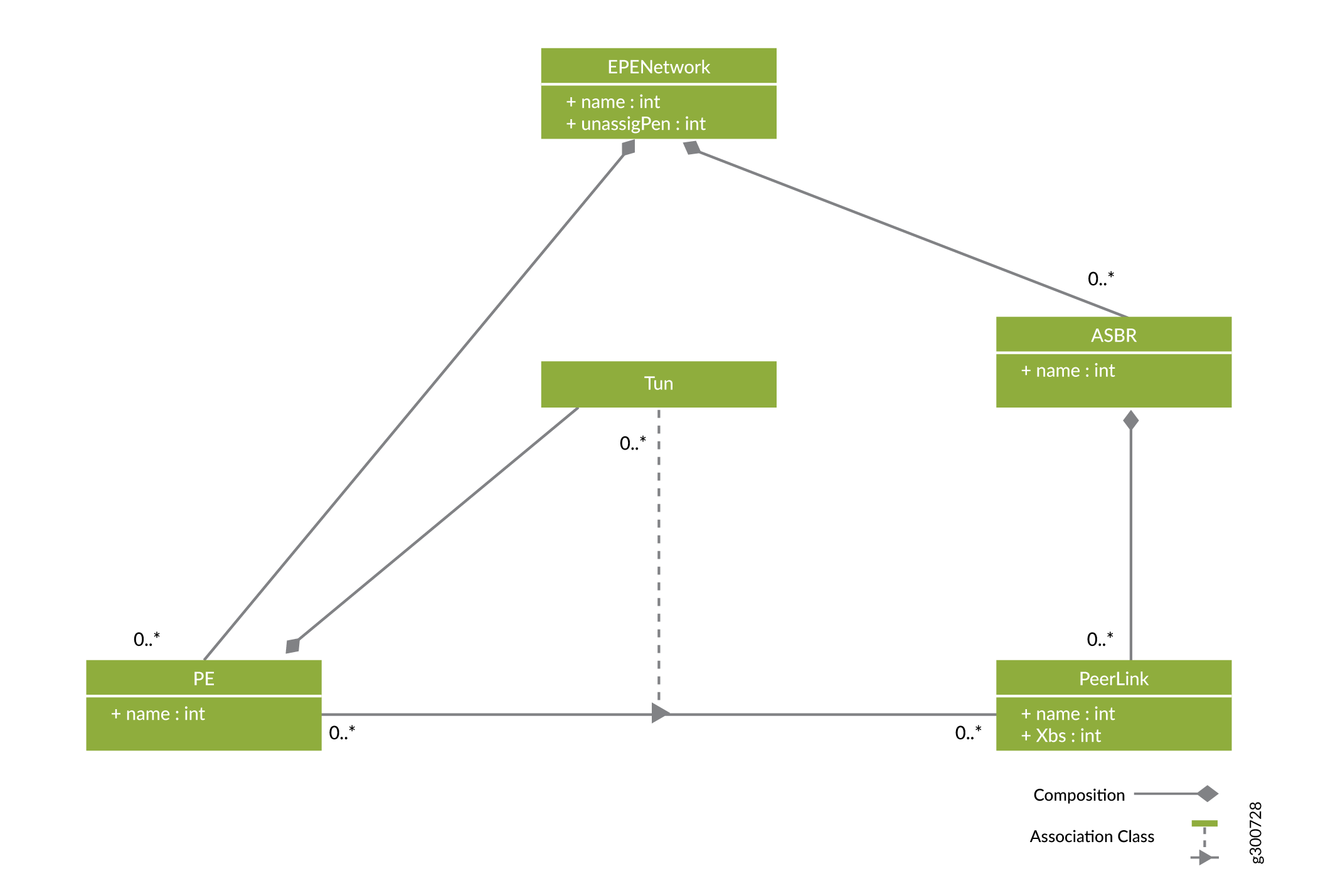
An EPE network is composed of a set named PEs, tunnels, and ASBRs. We recommend ensuring that PE and ASBR names are unique within the network. ASBRs can have a number of peer links with a traffic capacity in units of “X” bits per second (Xbs) measured in some form of network bandwidth (Gb/s, packets per second, and so on). Tunnels form a many-to-many relationship between PEs and peer links.
Figure 3 shows the elements of an EPE network.
Traffic Planning
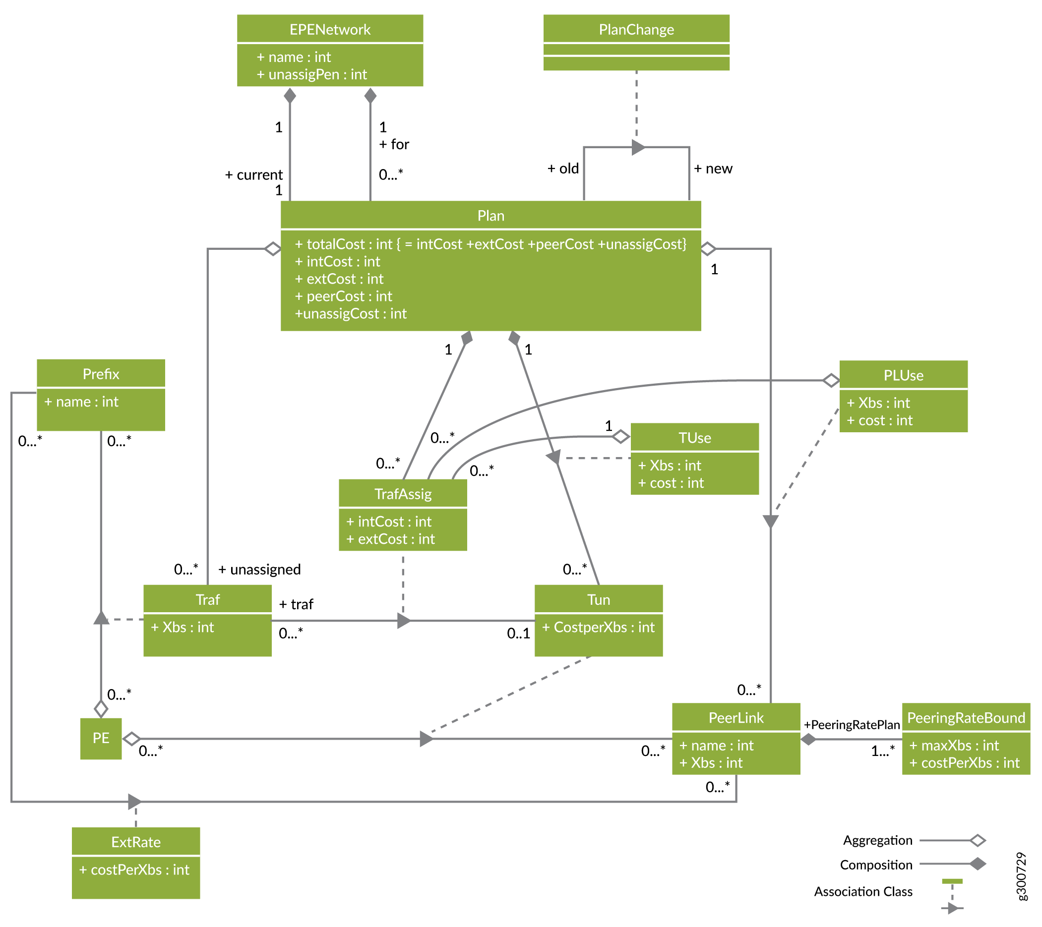
Traffic is a relationship between a PE and a prefix, measured in the same units as peer link traffic capacity. Traffic planning is devising plans by which some or all traffic is steered into tunnels.
Figure 4 shows the model for EPE traffic planning, including how traffic is specified for the network and how plans are devised to steer some or all of that traffic into tunnels.
Costs
Cost rates are measured per unit of traffic (bandwidth). There are three kinds of costs of engineering traffic:
Internal transit costs
External transit costs
Peering costs
It is assumed that a lower cost rate implies the tunnel, peer link, or external route is preferable to use from an EPE planning perspective, either because it actually costs less in dollars, it provides better quality of service, or it is better due to another factor or combination of factors.
There is an unassigned penalty in the EPE network that is used to weight the cost of the traffic that is not engineered by a plan (unnassignedPenalty). This is, essentially, a fourth cost. The cost of an EPE plan is the sum of the three costs of engineering traffic plus the cost of unassigned traffic.
Internal Transit Costs
Internal transit costs are specified by a cost-per-unit of traffic value (costPerXbs) in the tunnel object (Tun). An internal rate might reflect a number of different factors, such as the distance, number of hops, or other metrics of the tunnels between PEs and peer links.
External Transit Costs
External peer transit costs are specified by an external rate relationship between peer links and prefixes. This relationship reflects the cost to the peer to deliver the traffic to its ultimate destination from the ASBR on the far end of the peer link. Some examples are the distance, transit cost, delay, or other metrics of the peer ASBR to the ultimate location of the prefix.
Peering Costs
Peer link usage costs are specified by a peering rate plan (PeeringRatePlan), which consists of an ordered sequence of peering rate bounds (PeeringRateBounds) which have a rate cost-per-Xbs (costPerXbs) and a bound Xbs. An adjacent pair of peering rate bounds specifies a bandwidth interval (minXbs, maxXbs] and a charge rate for traffic in that interval in a way analogous to income tax brackets. The minXbs for the first bandwidth interval is 0, the minXbs for the rest is the maxXbs for the peering rate bound below. If a peering rate plan has last maxXbs B, the corresponding peer link has usage U, rate range bounds b0 = 0,b1,...,bn = B, and non-negative cost rates c1,...,cn for these ranges, then the peer link usage cost is:
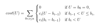
For example, if B = 10, U = 8, n = 3, and we have range bounds b0 =0, b1 =5, b2 =7, b3 = B =10 and costs for (0,5] ➝ 2= c1 , (5,7] ➝ 5= c2 , and (7,10] ➝ 10= c3 , then the peering rate plan and its evaluation for U would look like this:
More Than |
Not Exceeding |
Rate |
Cost |
|---|---|---|---|
0 Gb/s |
5 Gb/s |
$2 per Gb/s |
$2(5-0)=$10 |
5 Gb/s |
7 Gb/s |
$5 per Gb/s |
$5(7-5)=$10 |
7 Gb/s |
10 Gb/s |
$20 per Gb/s |
$10(8-7)=$10 |
Total cost = $30 |
Another way of looking at this is as a graph of a piecewise linear function as in Figure 5. The x axis is the Xbs value to rate and the y axis is the cost of that amount of traffic. The slopes of the linear pieces are the cost rates and the bounds are the points on the x axis where the slope changes. The cost of a certain traffic level is the result of mapping the point on the x axis to the corresponding point on the y axis.
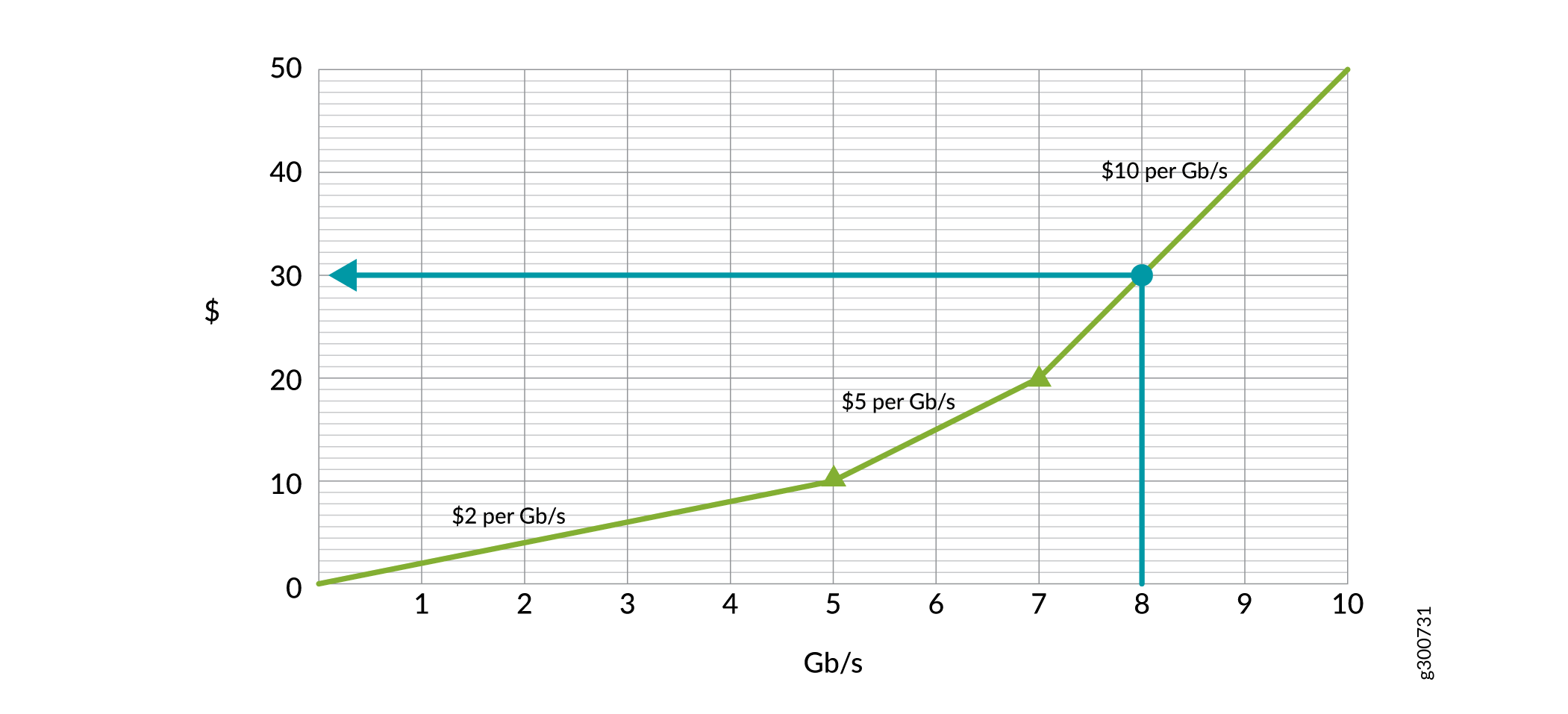
You can be creative with this scheme by:
Imposing very high costs at the top end to reserve space on links
Having high costs for low bandwidth, but volume discounts as traffic ramps up
Having free ranges
There is an EPE network global excess peer link (excessPeerLink) rate (in dollars per Xb/s) which is used to rate traffic in excess of the highest bound in a peer rating plan (PeerRatingPlan).
Example Network with Costs and Traffic
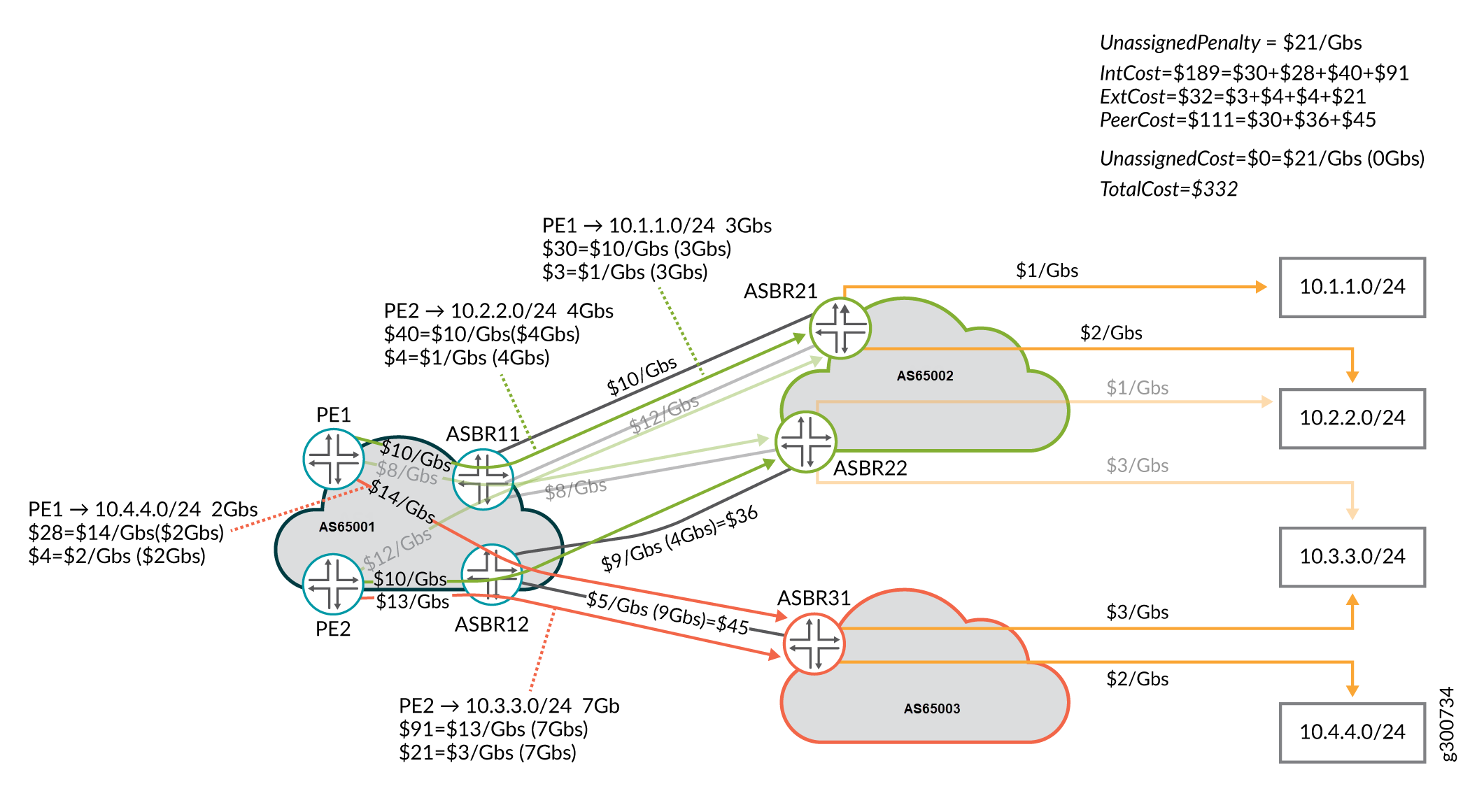
Figure 6 shows an example PE network. In this example, AS65001 is the subject of EPE and has peer links with AS65002 and AS65003. There are two PEs and two ASBRs in AS65001. ASBR11 has three peer links with AS65002: two with ASBR21 and one with ASBR22. ASBR12 has a peer link with ASBR22 in AS65002, and one with ASBR31 in AS65003. All peer links are assumed to be 10 Gb/s with single rate peering rate plans that vary from $5 per Gb/s to $12 per Gb/s as indicated.
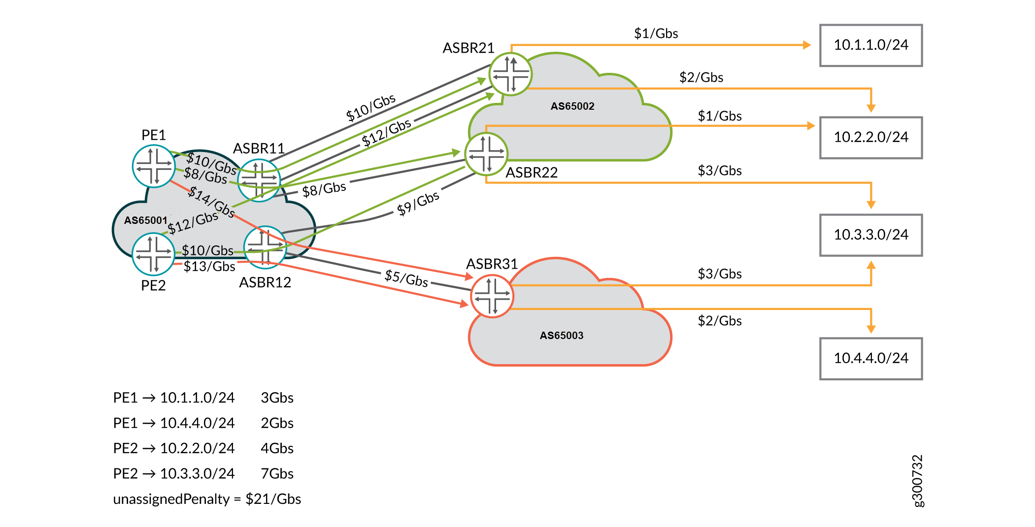
The EPE network has four prefixes which are in the top traffic list for the PEs. The external transit rates between the peer ASBRs and the prefixes are as indicated by the orange arrows.
The EPE network has four tunnels to AS2 and two tunnels to AS65003, as indicated by the green and red arrows, respectively. The traffic in the network is indicated by the key in the lower left of the figure. The unassigned traffic penalty is set to $21 per Gb/s. As we develop this example, you will see how that is relevant.
Plans
A plan for the EPE network with associated traffic and costs is a set of traffic assignments (TrafAssig) that assign some or all traffic to tunnels. This assignment implies tunnel-use (TUse) and peer-link-use (PLUse) relationships between the plan and the tunnels, and the plan and the peer links, respectively. Remember that a plan’s total cost is the sum of the internal and external transit costs, the peering costs, and the cost of the unassigned traffic.
The plan partitions the traffic into an unassigned set and an assigned set. The assigned set participates in a traffic assignment relationship, mapping traffic flows to compatible tunnels. A compatible tunnel is one that starts at the PE where the traffic flow enters the network, and ends on a peer link that connects to an ASBR with an external route to the prefix of the traffic flow. The traffic assignment relationship induces tunnel-use and peer-link-use relationships, tracking the use of the tunnels and peer links in the plan.
Traffic Assignment
A traffic assignment assigns the traffic for a prefix at a PE to a tunnel. The internal cost of the assignment is calculated by multiplying the traffic’s rate by the tunnel’s cost rate. The external cost of the assignment is calculated by multiplying the traffic’s rate by the peer link’s external rate.
Tunnel Use
If a plan uses a tunnel in one or more traffic assignments, there is a tunnel-use relationship between the plan and the tunnel. The Xbs used by the tunnel in the plan is the sum of the Xbs of the traffics assigned to the tunnel. The cost of the tunnel-use is the cost-per-Xbs for the tunnel.
Peer Link Use
A peer-link-use (PLUse) indicates the bandwidth usage and cost of a peer link in the plan. A peer link is used in a plan each time traffic is assigned to a tunnel that ends on that peer link. Only peer links that are actually used in the plan are included. The peer-link-use includes Xbs used and the cost of that use. The Xbs is the sum of all the traffic Xbs for traffic assigned to tunnels ending on the peer link. The cost is the peer link’s peering rate plan applied to the peer-link-use’s Xbs.
Plan Cost Breakdown
The peer cost for a plan is the sum of the costs of the peer-link-uses of the plan.
There are two ways to look at the internal and external costs of a plan:
Traffic assignment perspective:
The internal cost is the sum of the traffic assignment internal costs
The external cost is the sum of the traffic assignment external costs
Tunnel-use perspective:
The internal cost is the sum of the tunnel-use costs
The external cost is the sum over all tunnel-uses. For each traffic assigned to the tunnel in the plan, the Xbs of the traffic times the external rate of the prefix of the traffic for the peer link of the tunnel.
Unassigned Traffic
It is not necessary for a plan to assign all traffic to tunnels. Any traffic that is not assigned is tracked in an unassigned set. The cost of the unassigned traffic is the sum of the Xbs for that traffic times the unassigned penalty (unassigPen) factor for the EPE network. It is possible that the total cost of a plan with unassigned traffic is less than plans without unassigned traffic.
Plan Examples
Figure 7 shows a plan for the example EPE network in Figure 6. Traffic from PE1 to 10.4.1.0/24 and from PE2 to 10.4.3.0/24 are assigned to appropriate tunnels, and the rest of the traffic is left unassigned. The internal and external transit costs as well as the unassigned traffic penalties are show below the traffic. The used tunnels and peer links are annotated with their internal transit and peering costs, respectively. The breakdown of the total internal transit, external transit, peering, and unassigned traffic costs as well as the total cost of the plan are shown in the upper right.
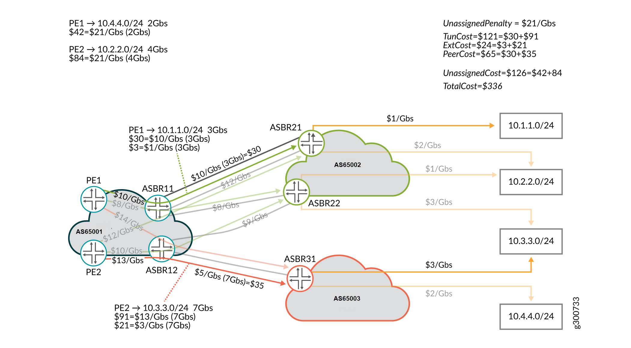
Figure 8 shows the optimal plan for the same network. It turns out that the cost is the same to leave the 2 Gb/s of traffic from PE1 to 10.4.4.0/24 unassigned as it does to have all traffic assigned.
Plan Changes
There are three plan change relationships that are interesting for the process of analyzing the differences between plans. These relationships are between the old plan and a new plan:
Traffic changes
Tunnel changes
Peer link changes
Traffic Changes
The traffic changes relationship (TrafChanges) is shown in Figure 9. This type of relationship consists of a traffic change for each traffic flow that had one of the following traffic assignment changes:
Unassigned to assigned
Change of tunnel assignment
Assigned to unassigned
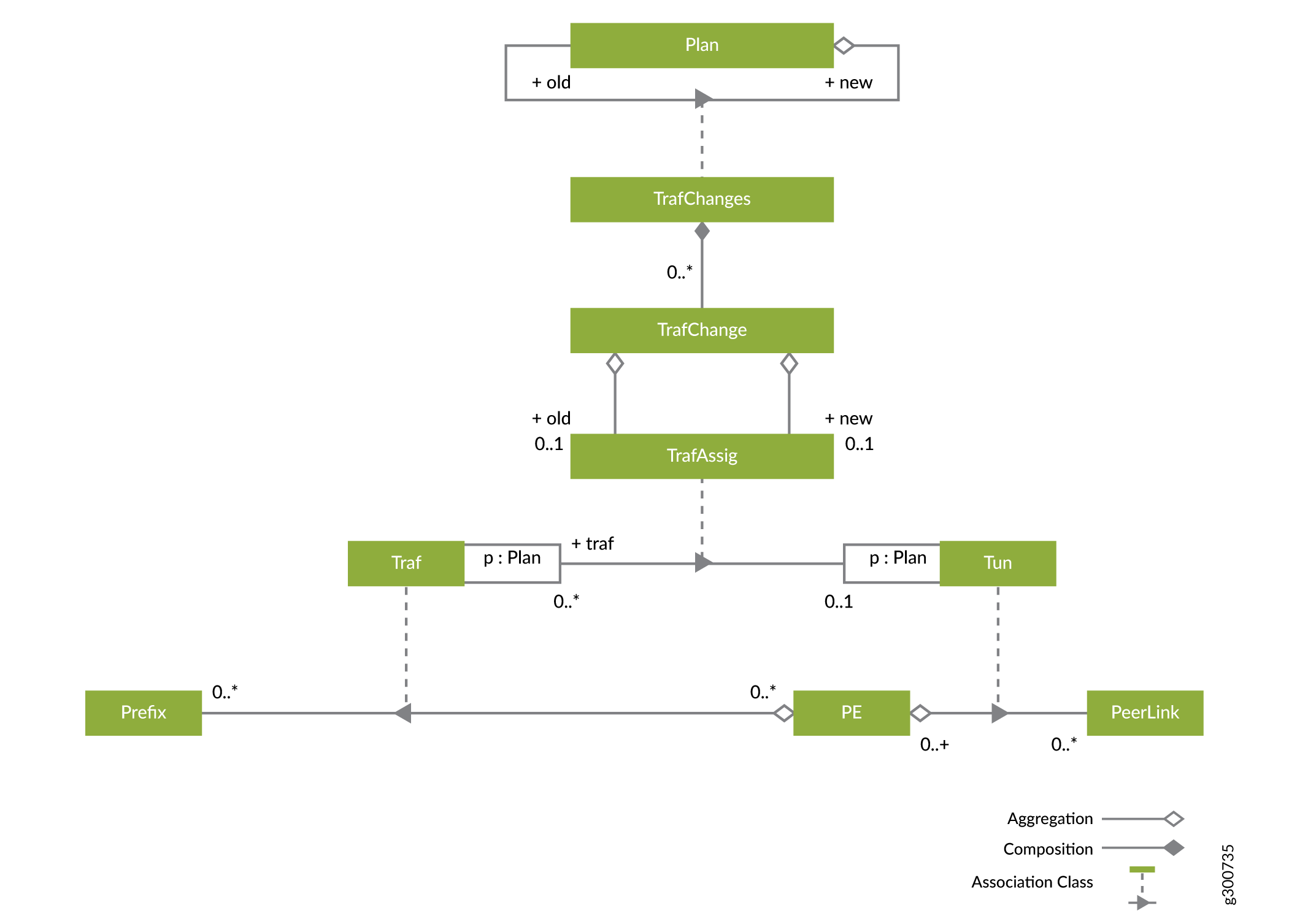
The old and new attributes of the traffic change indicate the old and new traffic assignments for the traffic whose assignment has changed. If the traffic was unassigned before the change, the old traffic assignments are not included. If the traffic is unassigned after the change, the new traffic assignments are not included.
Tunnel Changes
Tunnel changes represent the relationship between an old plan and a new plan. Tunnel changes summarize the total number of tunnels changed, the total number of pieces of traffic moved, and the total amount of Xbs moved in all changes.
Tunnel changes (TunnelChanges) aggregate a set of individual tunnel change (TunnelChange) objects—changes to individual tunnels. Some or all of the tunnels could be changed. There is a single pseudo-TunnelChange with no associated tunnel that represents changes to the unassigned traffic. The TunnelChanges object:
Summarizes how much Xbs was used by the tunnel before and after the change
Breaks down the set of traffic on the tunnel before and after the change
Breaks down the traffic that was added to and deleted from the tunnel as a result of the change
Peer Link Changes
There is a similar peer link change relationship between plans that describes how peer links change in the transition from one plan to another.
Plan Change Example
Table 1, Table 2, Table 3, Table 4, and Table 5 summarize the plan change between the two plans shown in Figure 7 and Figure 8 . Table 1 shows the cost changes. Table 2 totals the number of traffic, tunnel, and peer link changes, and shows the total traffic moved in Gb/s. The remaining three tables break down the traffic, tunnel, and peer link changes.
This is a simple example where traffic only changes from unassigned to assigned. In practice, traffic can be moved from one tunnel and/or peer link to another, or can be moved to unassigned.
Cost Type |
New Cost |
% Change |
|---|---|---|
Internal |
$186 |
+36% |
External |
$30 |
+27% |
Peering |
$116 |
+40% |
Unassigned |
$0 |
-100% |
Totals |
$332 |
-1.2% |
Traffic Changes |
Tunnel Changes |
Peer Link Changes |
Traffic moved |
|---|---|---|---|
2 |
2 |
2 |
6 GB/s |
Traffic |
Old Tunnel |
New Tunnel |
|---|---|---|
10.4.4.0/24 |
NA |
PE1→12_31 |
10.4.2.0/24 |
NA |
PE2→12_22 |
Tunnel |
Old |
New |
|---|---|---|
Pseudo-tunnel (unassigned traffic) |
PE1→10.4.4.0/24 |
|
PE2→10.4.2.0/24 |
||
6 Gb/s |
0 Gb/s |
|
PE1→12_31 |
|
10.4.4.0/24 |
0 Gb/s |
2 Gb/s |
|
PE2→12_22 |
|
10.4.2.0/24 |
0 Gb/s |
4 Gb/s |
Peer Link |
Old |
New |
|---|---|---|
Pseudo-tunnel (unassigned traffic) |
PE1→10.4.4.0/24 |
|
PE2→10.4.2.0/24 |
||
6 Gb/s |
0 Gb/s |
|
12_22 |
|
PE2→10.4.2.0/24 |
0 Gb/s |
4 Gb/s |
|
12_31 |
PE2→10.4.3.0/24 |
PE1→10.4.4.0/24 |
PE2→10.4.3.0/24 |
||
7 Gb/s |
9 Gb/s |
Execution Plans
Figure 10 shows the model for executing changes to the EPE Plan. An execution plan (ExecPlan) has a start plan and an end plan. The start plan is the current EPE plan that is active in the network. The end plan is the optimized EPE plan—the target.
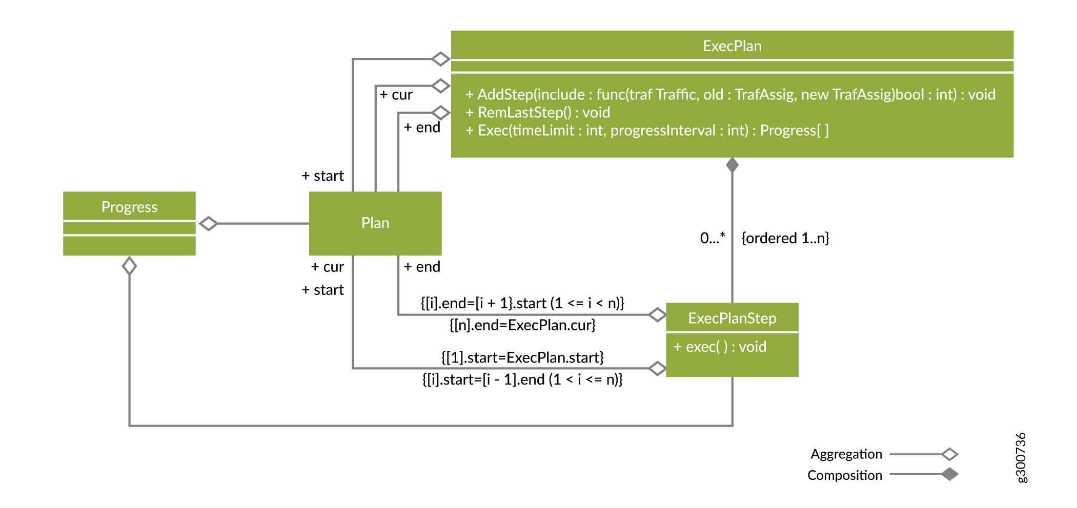
An execution plan for a plan change is a sequence of execution plan steps (ExecPlanSteps) which are themselves smaller plan changes. The steps, put back to back, add up to the overall plan change (or part of it if the execution plan is incomplete). The start plan for the first execution plan step is the start plan for the whole execution plan. The start plan for each subsequent step is the end plan for the previous step. The end plan for the last step is the current (cur) plan for the whole execution plan. If the current plan is not the execution plan’s end plan, then the execution plan is incomplete in that it doesn’t go all the way to the end plan.
An execution plan is created by adding execution plan steps and possibly backtracking from time to time by removing the last added step. The add-step (AddStep) method takes an include predicate which tests each of the remaining traffic assignment (TrafficAssignment) changes needed to get from the current plan to the end plan. If include returns true, the traffic assignment change is included in the added execution plan step.
At any time, you can take a look at the intermediate plans that will result from running with the execution plan, to decide if the results are acceptable. It may be the case that a step turns out to be unacceptable. For example, an intermediate plan might be too expensive, might cause too much churn in the network, or might temporarily makes an LSP’s or peer link’s bandwidth too high. In this case, it might be desirable to backtrack by calling remove-last-step (RemLastStep) and try something different.
Once the execution plan is complete and acceptable, the execute (Exec) command is called to apply the execution plan in the network. This causes the traffic assignment changes in the execution plan steps to be applied, in order, and in parallel within the execution plan step. There is a synchronization at the end to ensure that the end of each execution plan step is in place before the next execution plan step is started.
While the execution plan is executing, a stream of progress notifications are sent back to you, to provide feedback on the progress of the execution. These notifications are created based on the detailed progress report. The detailed progress report contains information about the execution plan step that is currently executing and a current plan describing what is confirmed to be operational in the network.
Executing an ExecPlan consists of two types of changes in the network:
Changing tunnel bandwidth (optional)
Changing demand LSP bindings (which effect traffic assignment changes)
Each execution plan step groups a set of traffic assignment changes together to be executed as a group of demand LSP binding changes in NorthStar Controller terminology. If optional tunnel bandwidth maintenance is requested, tunnel bandwidth is managed in a “make before break” fashion. This means the bandwidth on tunnels that will experience a net gain of traffic as a result of the execution plan step is increased before any traffic is moved. This ensures that the bandwidth is available before moving any traffic. After all the traffic moves in the execution plan step are complete, the bandwidth on the tunnels that experience a net loss of traffic is reduced.
When optional tunnel bandwidth maintenance is requested, there is another subtlety for tunnels that are not getting any traffic assignment changes as a result of the requested plan change. Since traffic conditions have changed since the last time their bandwidths were set, they might need updates to reflect the current traffic conditions. So the general sequence of the network operations with optional tunnel bandwidth maintenance is:
Unaffected Tunnel bandwidth changes
ExecPlanStep 1 Tunnel bandwidth increases
ExecPlanStep 1 TrafficAssignment changes
ExecPlanStep 1 Tunnel Bandwidth decreases
ExecPlanStep 2 Tunnel bandwidth increases
ExecPlanStep 2 TrafficAssignment changes
ExecPlanStep 2 Tunnel Bandwidth decreases
...
ExecPlanStep N Tunnel bandwidth increases
ExecPlanStep N TrafficAssignment changes
ExecPlanStep N Tunnel Bandwidth decreases
During the traffic assignment changes phase of an execution plan step, the current plan is normally some intermediate plan between the start and end plans of the step. The progress notifications have two types, one for a tunnel bandwidth change phase, and one for a traffic assignment change phase. You can use the REST API to view the detailed progress report.
Pacing the Rate of Operations
Testing shows that Junos PRPD/SR/Steering functionality is very sensitive to load and routing can be adversely affected if the functionality is driven too hard by NorthStar. As a result, when executing a plan change, the EPE Planner must pace the rate of operations that change the network. You can access the exec-pace-rate setting through the NorthStar CLI to help control this. Use the set northstar peer-engineering egress application exec-pace-rate command. You can also manage this through a setting in the REST API.
The exec-pace-rate setting is the maximum rate at which the EPE Planner executes NorthStar REST API calls that change the network, in units of calls per second. The NorthStar REST API calls that the EPE Planner executes in the process of executing a plan change are:
Posts, Patches, Puts, and Deletes of demands to change the LSP bindings and steer traffic
Patches of LSPs to change the tunnel bandwidth
The setting is:
In the NorthStar CLI: set northstar peer-engineering egress application exec-pace-rate command.
In the settings managed by the REST API: “execPaceRate": {{float32}}.
The default value for this setting is 0.5 (network changes per second), so by default, the EPE Planner makes a REST API call to NorthStar which changes no faster than once every two seconds. When modifying this setting, be aware that slower (lower setting) is safer.
Projects
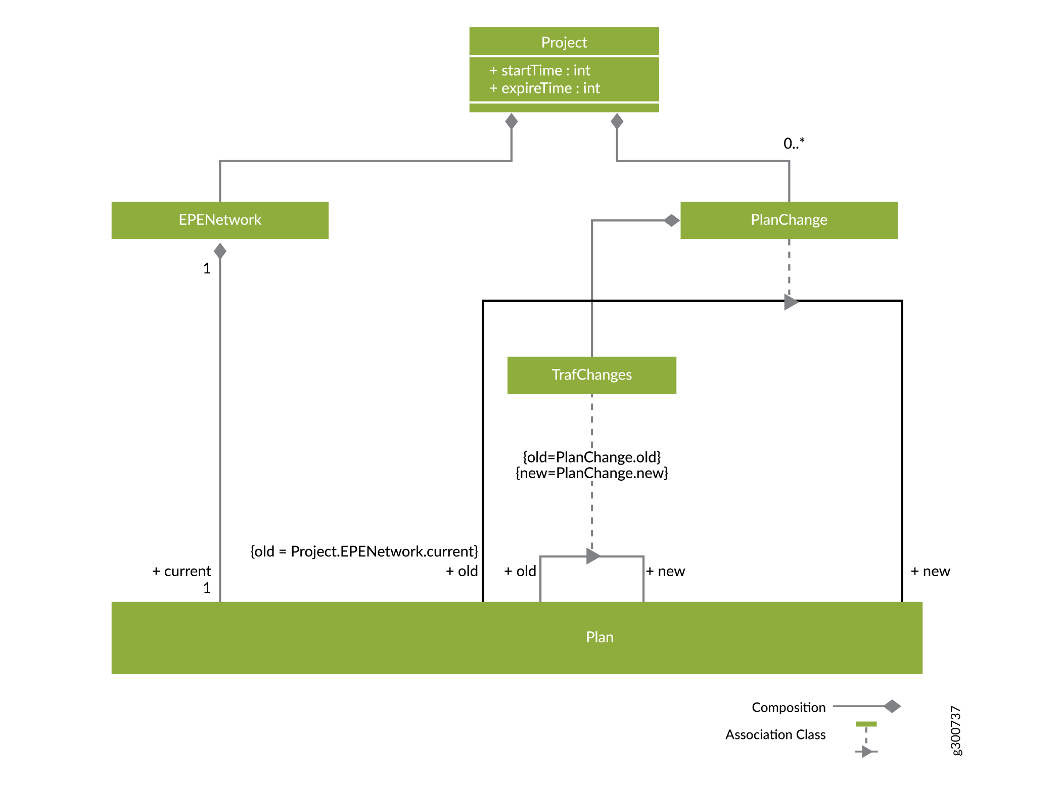
When using the EPE Planner application, you work on projects. The model for projects is shown in Figure 11. When you want to initiate a new planning session, you create a project. Initially, the project loads an EPE network (EPENetwork) and associated current plan which is created based on a snapshot of the live network’s demands, tunnels, links, and nodes. You receive a sequence of progress notifications, culminating in a “loading complete” notification along with the status of the load process (whether it succeeded or failed). This snapshot drifts away from reality as things change in the network, so a planning session is normally completed in one interactive session. Since you might wish to leave the planning session and return to it later, a project has a start time (startTime) and an expiration time (expireTime). After the expiration time has been reached, the EPE Planner automatically deletes the project.
After initiating the session, you can direct the EPE Planner to consider moving traffic around in search of plan changes that improve the current plan. This is a long-running operation with a configurable time limit. You receive a notification each time a qualified (improves costs) plan change is found. If no such plan changes are found within the time limit, the search ends. Otherwise, you are presented with the plan changes that were found. A plan change, remember, is a relationship between an old plan (the current plan) and a new plan which has a total cost lower than the current plan. You can look at a plan change from a traffic, tunnel, or peer link perspective, as described in Plan Changes.
You can select a plan change and create an execution plan for it. The model for this is shown in Figure 12.
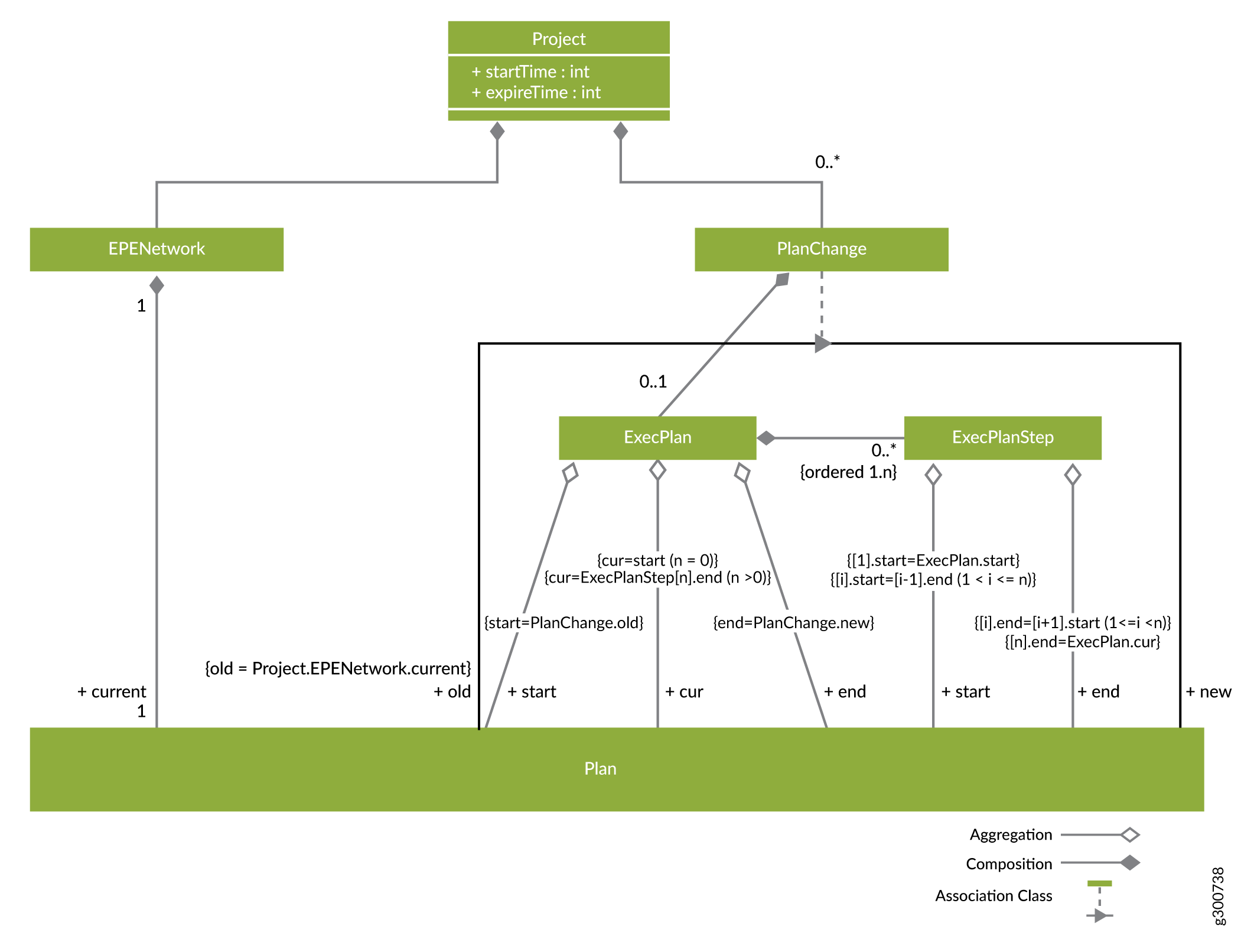
Remember that an execution plan (ExecPlan) is a way of breaking down the plan change (PlanChange) into execution steps (Steps) that are smaller, safely executable plan changes. The goal is to create an execution plan that implements the whole plan change, but you can also create partial execution plans that only implement some of the overall plan change.
The steps are executed in order, and accumulated together, they add up to a change from the start to the current plan of the execution plan. If the current plan is the end plan, then it’s a complete execution plan for the plan change.
You can interactively construct and simulate execution plans to get an understanding of and confidence in the steps they will take to implement the plan change in the network. When you’re ready, you can direct the EPE Planner to apply the execution plan in the network and monitor its progress.
When you execute the plan change in the network, progress notifications are provided according to an interval that you configure. The execution of the plan change either finishes within the configured time limit (success) or is stopped early due to the time limit (failure). The final progress notification includes where the plan change execution ended up and its final status, and the project (planning session) is terminated. The execution plan is complete when its current plan is the same as its end plan.
The workflow for a project, as shown in the Overview section (Figure 1) is cyclical. Once completed, the whole process can begin again by loading the EPE network and (new) current plan.
Be aware of the “stale project” concept. A project is stale if there is another project that made progress executing since this project was created. A stale project is read-only; no operations can be performed on it.
Detailed Steps for Discovering the Network, Traffic, and Current Plan
The EPE Planner application proceeds through the following steps to discover the network, traffic, and current plan:
The EPE Planner requests the demands from the NorthStar REST API. From this, the application gets the traffic bandwidth for the top demands between a PE and a (local) ASBR. The from and to values are IP addresses of routers—the PE, and the local ASBR involved in the demand.
If the EPE Planner cannot find a router with the specified IP address, it warns that the demand cannot be planned for.
It is allowed that the same prefix/PE combination could have a demand to one or more local ASBRs (ECMP routing or multiple tunnel bindings, for example). In this case, the traffic will be the sum of the bandwidth for all such demands.
The bandwidth for the demand comes from the live properties or the planned properties. If both have a bandwidth property, the live properties take precedence.
If a demand has an LSP binding, there is a corresponding traffic assignment to a tunnel in the current plan.
The application requests the EPE LSPs from the NorthStar REST API. To be considered an EPE tunnel, the LSP must be provisioned with “SR”, have a color, and have usePenultimateHopAsSignallingAddress set to true.
Logically, the REST GET is performed first with collectedProperties, then a second time with plannedProperties. If an EPE LSP is found to have both collected and planned properties, the attributes in the collectedProperties take precedence.
The peer link for the tunnel is the final entry in the calculated ERO, and it must be the name of a link. If not, the application logs a warning that the LSP will not be used for EPE planning.
An EPE property “internalRate” can be used to store the internal cost of the tunnel. The value is an integer.
The EPE Planner logs a warning if there is a demand with a binding LSP which is not found among the LSPs that are deemed eligible for EPE. In this case, the related traffic is considered unassigned in the current plan.
Get the peer links.
The EPE Planner gets all links and processes those with IDs seen in EPE tunnels. It logs an error for any link seen in an EPE tunnel but not found.
The application looks for two EPE properties: EPE bandwidth (EPEBandwidth) and peering rate plan (peeringRatePlan). EPE bandwidth must be an integer, and is the Xbs used for the peer link. The EPE bandwidth is the amount of bandwidth reserved on the link for EPE, which could be less than the total link bandwidth. The peering rate plan is a sequence of (bound,rate) pairs, defining the peering rate plan.
The application gets the PEs and ASBRs involved in the EPE network. A database is built with all routers that occur in a demand (by IP address = routerId), an EPE tunnel (by IP address), or peer link (by ID).
hostName is used as the name of the PE or ASBR in the EPE network.
The EPE property external rates (externalRates) is used on the ASBR on the remote ends of peer links to provide the external rate plan for those peer links. These prefix-rate mappings indicate the external cost of sending traffic from the peer links connected to the remote ASBR to a prefix. Prefixes not included in the mapping are considered “not reachable” from the associated peer links.
Create a new EPE network with the unassigned traffic penalty and excess peer link cost values provided as parameters to the planning process. An empty current plan is created automatically.
Add the prefixes found in demands to the network.
Add the PEs to the EPE network based on the information retrieved in previous steps.
The traffic for prefixes entering at the PE is added to the network.
ASBRs are added to the network.
Peer links for the ASBR are added to the network.
External rates for prefixes are added to the peer links.
Peer rating plans are added to the peer links. 0 is the implicit lower bound for the first range in the plan and does not need to be specified.
The maximum bound can be greater than the peer link bandwidth so plans can be formulated even when there is so much traffic that overloaded peer links are required. If a plan assigns more traffic to the peer link than the maximum bound, then the excess peer link cost specified when the network is created is used to rate the excess traffic.
Tunnels are added to the PEs in the network. The default internal cost rate is 0 if unspecified.
Traffic assignments are added to the current plan for the network, based on the binding LSPs found with the demands.
Detailed Steps for Proposing New Plans for an EPE Network
The EPE Planner application proceeds through the following steps to propose new plans for how to handle the traffic in an EPE network:
You specify what currently-assigned traffic the EPE Planner application is free to move, in the search for improvements to the current plan. Supported free traffic test types are:
Free up all traffic assignments in the current plan.
Free up none of the traffic assignments in the current plan.
Free up the listed traffic assignments in the current plan.
Free up all traffic assignments on peer links where peer link use/bandwidth ≥ minUseRatio; minUseRatio is not negative.
Free up all traffic assignments on tunnels where tunnel use ≥ minUse; minUse is not negative.
Free up traffic assignments where traffic bandwidth ≥ minBandwidth; minBandwidth is not negative.
Free up traffic assignments where traffic bandwidth ≤ maxBandwidth; maxBandwidth is not negative.
Free up traffic assignments where traffic is in the top k of all traffic; k is not negative or zero.
Free up traffic assignments where traffic is in the bottom k of all traffic; k is not negative or zero.
You request plans to be created, specifying a time limit for searching for and improving upon plans.
Asynchronously, the EPE Planner component creates a sequence of plans meeting the requirements, each less costly than the previous.
A new plan created by the EPE Planner changes the traffic assignments that it is free to move, and also considers assigning any unassigned traffic.
The plans are reported back to the EPE Planner application, one by one. After the final plan is reported, the EPE Planner can determine if it is optimal or just the best one that was found before the time limit expired. The EPE Planner allows you to browse through:
The traffic assignments in the plan.
The tunnel-uses in the plan.
The peer-link-uses in the plan
Detailed Steps for Evaluating a New Plan
Using the EPE Planner application, you proceed through the following steps to evaluate a new plan, determining if it should be applied in the network. Beyond looking at the new plan in isolation as in the previous set of steps, you might want to look at the traffic assignment changes that would be required to execute the plan. The changes can be looked at in general, by tunnel, and by peer link.
You can browse the list of plan changes, sorting them by criteria such as cost of the end plan, or number of changes required.
You can also dig deeper into promising plan changes, searching, highlighting, and animating particular changes that are proposed.
Detailed Steps for Creating an Execution Plan
Once a new plan is selected, you formulate an execution plan (a sequence of steps) that updates LSP bandwidths and bindings in the network until the new plan is achieved. You do this by specifying which of the remaining traffic changes not already in a step should be included in the next step.
Traffic change tests (TrafficChangeTest) are used to evaluate if each of the remaining traffic changes should be included in the next step. The EPE Planner supports the following traffic change tests:
Include traffic changes involving a peer link. Optional direction specifies the traffic change is either from or to the indexed peer link. If direction is omitted, it is treated as both from and to.
Include traffic changes involving a tunnel. Optional direction specifies the traffic change is either from or to the indexed tunnel. If direction is omitted, it is treated as both from and to.
Include traffic changes involving unassigned traffic. Optional direction specifies the traffic change is either from or to unassigned. If direction is omitted, it is treated as both from and to.
Include traffic where bandwidth ≥ minBandwidth; minBandwidth cannot be negative.
Include traffic where bandwidth ≤ maxBandwidth; maxBandwidth cannot be negative.
Include traffic in the top k of traffic remaining to change; k cannot be negative or zero.
Include traffic in the bottom k of traffic remaining to change; k cannot be negative or zero.
Include specific traffic changes.
Include all traffic changes.
At any time, you can simulate and dig into the details of the execution plan as it stands, watching for problems such as overloaded links or expensive intermediate steps. This can help you gain confidence that the execution plan can be safely and efficiently executed in the network.
At any time, you can remove the last step if you want to backtrack and try something different.
Finally, you add the remaining traffic assignment changes to a last execution plan step to complete the execution plan.
Detailed Steps for Applying the Execution Plan in the Network
You request the execution of the execution plan and specify a time limit for how long the EPE application should spend trying to execute and an interval for progress updates. Here’s what happens next:
The execution plan executes each plan step, in order, in a make before break fashion, which means that for each step:
It first increases the bandwidth of all LSPs that get more traffic as a result of the execution plan step.
Next, it changes the LSP bindings of all demands that are affected by the step. Demands for the PE and prefix that don’t go to the ASBR of the assigned tunnel are deleted. If there is no demand for the PE and prefix that goes to the ASBR of the assigned tunnel, the execution plan creates one.
Finally, it decreases the bandwidth of all LSPs that get less traffic as a result of the execution plan step.
Each time a tunnel bandwidth change or a traffic assignment change is successfully applied in the network, the execution plan creates a progress report and saves it in a progress history for the execution plan.
At the specified progress interval, the EPE Planner delivers a notification for the latest progress report in the history to the client(s) who are following EPE notifications.
Configuration Parameters
The configuration parameters in Table 6 and Table 7 are used by the NorthStar Planner. With the exception of exec-pace-rate, we do not recommend that you change the value associated with any of these parameters unless instructed to do so by JTAC. See Pacing the Rate of Operations for information about why the value of the exec-pace-rate parameter might need to be modified.
Parameter |
Default Value |
Supported Values |
Description |
|---|---|---|---|
notification-types |
amqp |
amqp, file |
Configures the destination types for the notifications generated during execution. The type, “file” has to be used only for debugging/troubleshooting purposes. Setting this value allows notifications to be sent to a file. NorthStar CLI command: set northstar peer-engineering egress notification notification-types |
mq_host |
127.0.0.1 |
IP Address |
Configures the host on which the AMQP service is running. Maintained in the northstar.cfg file. |
mq_port |
5672 |
Port number |
Configures the port on which the AMQP service is running. Maintained in the northstar.cfg file. |
mq_username |
N/A |
AMQP username |
Configures the username to be used for connecting to the AMQP service. Maintained in the northstar.cfg file. |
mq_password_enc |
N/A |
Encrypted AMQP password |
Configures the encrypted password to be used for connecting to the AMQP service. Maintained in the northstar.cfg file. |
mq_max_channels |
128 |
1..2047 |
Configures the maximum number of channels that can be multiplexed over a single AMQP connection. |
northstar-rest-client host |
127.0.0.1 |
IP address |
Configures the host on which the NorthStar REST API service is running. NorthStar CLI command: set northstar peer-engineering egress northstar-rest-client host |
northstar-rest-client port |
8443 |
Port number |
Configures the port serviced by the NorthStar REST APIs. NorthStar CLI command: set northstar peer-engineering egress northstar-rest-client port |
admin_username |
admin |
NorthStar username |
Configures the username for connecting to the NorthStar REST API service. Maintained in the northstar.cfg file. |
admin_password_enc |
N/A |
Encrypted NorthStar password |
Configures the encrypted password for connecting to the NorthStar REST API service. Maintained in the northstar.cfg file. |
northstar-rest-client allow-rest-insecure |
true |
true/false |
A value of true avoids logging warnings about improper server certificates. NorthStar CLI command: set northstar peer-engineering egress northstar-rest-client allow-rest-insecure |
exec-pace-rate |
0.5 |
Execution pace rate |
Configures the maximum pace rate to change the network in units of calls per second to avoid problems with PRPD/SR/Steering loading and routing. NorthStar CLI command: set northstar peer-engineering egress application exec-pace-rate |
Parameter |
Default Value |
Supported Values |
Description |
|---|---|---|---|
notification filename |
“.” |
Valid location in the NorthStar installation |
Configures the location and name of the filename into which notifications are to be written. This configuration must only be used for debugging or troubleshooting purposes. NorthStar CLI command: set northstar peer-engineering egress notification filename |
northstar-rest-client protocol |
https |
https, http |
Configures the protocol used to access the NorthStar REST APIs. This value should always be https in a production system. This configuration has to be used only for debugging or troubleshooting purposes. NorthStar CLI command: set northstar peer-engineering egress northstar-rest-client protocol |