Network Information Table Bottom Tool Bar
The bottom tool bar in the network information table has tools for navigating through the network element data, as well as Add, Modify, and Delete buttons for performing actions on elements.
The Add, Modify, and Delete buttons behave differently, depending on which type of element you are working with; these functions are not always allowed. When they are not allowed, the buttons are grayed out. The Modify and Delete buttons become enabled when an individual element row is selected, as long as the action is allowed on that element.
The topology server (Toposerver) requires that certain conditions be met before it will allow you to delete a link or node.
To delete a link:
The link’s operational status must be down. The operational status is changed to down when Toposerver receives the first LINK WITHDRAW message from NTAD.
The link cannot have active IS-IS or OSPF adjacencies. IS-IS and OSPF adjacencies are dropped when Toposerver receives the second LINK WITHDRAW message from NTAD.
To delete a node:
The node must be isolated, meaning that all links associated with the node have been deleted (after the link deletion conditions have been met).
The node cannot have IS-IS, OSPF, or PCEP connections. IS-IS and OSPF adjacencies are cleared when Toposerver receives a NODE WITHDRAW message from NTAD and the PCEP session has been terminated. This workflow ensures that TED and Toposerver are synchronized.
For some elements, you can modify or delete multiple items at once (bulk modify) by Ctrl-clicking or Shift-clicking multiple line items in the table. For example, if you select multiple items in the Tunnel tab and click Modify, the Modify LSP (X LSPs) window is displayed as shown in Figure 1.
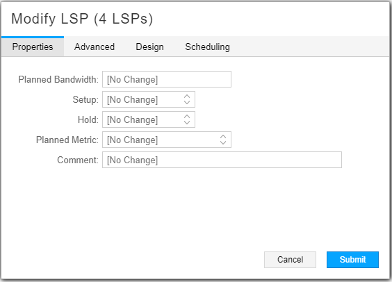
The window supports deleting the contents of a field, leaving the contents unchanged, or changing the contents to a specific value. Depending on the type of data the field contains, you can click to toggle, use the up and down arrows to select a value, or double-click to set a value. For fields where a blank value is not allowed (required fields), the option to delete is not available.
In some Add windows, a world icon is available beside certain fields. Clicking this icon allows you to select the field entry from the topology map instead of using the drop-down menu. This is a time-saving convenience. Figure 2 shows an example of this icon.
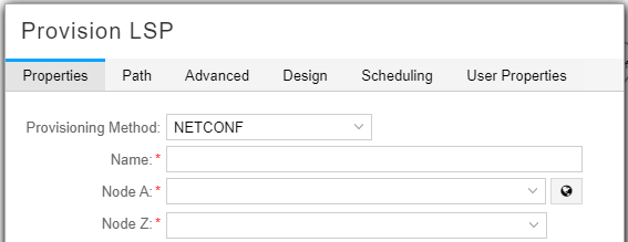
For example, if you are adding an LSP and you click the icon beside the Node A field, the Provision LSP window moves itself to the lower left corner of your screen to give you access to the topology map. You click the node you want to use for Node A, then click the node you want to use for Node Z. The Node A and Node Z fields are populated for you.
Navigation Tools
The tools in the network information table bottom tool bar are available to help you navigate through rows of data, refresh the display, and change the number of rows per loaded page. These tools are especially useful for large models with many elements.
Table 1 describes the tools in the bottom tool bar. Not all of the tools are available for all element types (node, link, interface, and so on).
Tool or Button |
Description |
|---|---|
<< |
Displays the first page of data. |
< |
Displays the previous page of data. |
Page __ of <total pages> |
Displays the specific page of data you enter. |
> |
Displays the next page. |
>> |
Displays the last page. |
|
Causes the web UI client to retrieve the latest data from the NorthStar server. This button turns orange to prompt you to refresh when the display is out of sync. |
|
Downloads the table information to spreadsheet. |
|
Opens a search criteria field at the top of the network information table. Enter the search criteria and click the Filter button on the far right of the field. The table filters out rows that do not contain the search criteria somewhere in the row. Click the X beside the Filter button to clear the filter. Note:
Searches are not case sensitive. See Table 2 for tips on constructing search criteria. |
|
This button is available in the Node, Link, Tunnel, and Demand tabs, and has two behaviors, depending on the tab. In the Node and Link tabs, the button is not functional unless you have filtered the table contents. For filtered contents, clicking the button causes the topology map to display only the elements that are included in the filtered contents. In these tabs, mousing over the button shows “Automatic filter to Topology map”. Note:
In the Node and Link tabs, you can select rows in the network information table, right-click the rows, and select Filter Selected Node/Link to filter the topology display without filtering the network information table. In the Tunnel and Demand tabs, the button is for unfiltered contents. If you select a subset of table rows, the corresponding tunnels are highlighted in the topology map. If you click this button, the topology map limits the display to only the nodes related to those selected tunnels. The network information table still displays all tunnels, with the selected tunnels highlighted. In these tabs, mousing over the button shows “Hide unrelated nodes from Topology map”. In both cases, the icon is highlighted when it is activated. To deactivate it and restore the full topology display, click the button again. |
|
Click the down arrow to specify a grouping for the table contents. |
|
Settings for:
|


The search/filter tool launched with the magnifying glass icon at the bottom of the network information table has a number of syntax options that are described in Table 2.
Syntax |
Behavior |
|---|---|
Simple string (no spaces) |
Every column is checked against the search string. All rows containing matching text anywhere in the row are displayed. Rows not containing matching text are filtered out. Searches are not case sensitive. |
== |
Compares a specific column with a specific value. For example, hostname==vmx101 checks the Hostname column and displays only those rows containing the search string vmx101. Other rows are filtered out. |
</<=/>/>= |
Less than, less than or equal to, greater than, and greater than or equal to can be used similarly to ==. For example, AS>3 displays only rows where the AS column has a value greater than three. |
“column name” |
Any column name that contains a space must be enclosed in quotation marks. For example, “node a”, not node a. “Node a”==vmx104 checks the Node A column and displays only those rows containing the search string vmx104. Other rows are filtered out. |
!= |
Not equal to. Excludes rows that contain the search criteria. For example, “node a”!=vmx104 checks the Node A column and displays only those rows that do not contain the search criteria vmx104. Rows that contain vmx104 in the Node A column are filtered out. |
and/or |
You can string multiple search criteria together using and/or. For example, “node a”==vmx102 and “path type”!= primary displays only rows in which the Node A column contains the search string vmx102 and the Path Type column does not contain the search string primary. |
(expression) |
An expression enclosed by parentheses has precedence. For example, in the expression (“node a”==vmx101 or “node a”==vmx102) and “path type”!= primary, the part in parentheses is evaluated first. Rows match if column Node A contains either vmx101 or vmx102, and column Path Type does not contain primary. |
==“ ” |
An empty search string matches if there is no value in the specified column. For example, “PRPD Status”==“ ” displays all rows for which there is no value in the PRPD Status column. |
!=“ ” |
Not equal to combined with an empty search string matches rows that have any value in the specified column. For example, type!=“ ” displays all rows that have any value in the Type column. |
Actions Available for Nodes
For nodes, the Add function is available, specifically for adding customer edge (CE) nodes and sites (multiple CE nodes in one location). The Add Node window is shown in Figure 3.
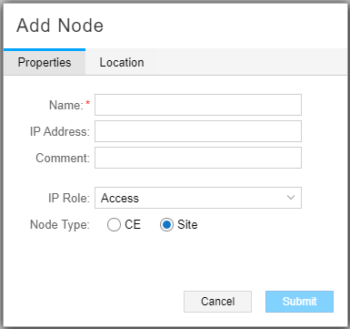
CE nodes and sites are used when configuring P2MP tree design with diverse PE-CE links. This type of tree design allows diverse tree calculation to be performed all the way to the intended traffic endpoints (the CE nodes/sites), even though the P2MP trees need to terminate on the PEs connecting to the sites. See Provision and Manage P2MP Groups for more information about P2MP tree design with diverse PE-CE links, including information about the IP Role options available for the CE node or site in the Add Node window.
Delete is allowed as long as the prerequisites for node deletion have been met, as described earlier in this topic. Modify is allowed and is optionally used to set or change the latitude and longitude of a node, change node properties, or add IP addresses.
Figure 4 shows the Properties tab of the Modify Node window. All of the fields on this tab can be modified.
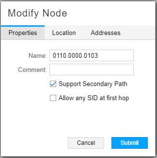
The default for Support Secondary Path is enabled (checked).
The default for Allow any SID at first hop is disabled (unchecked).
When disabled, NorthStar forces the first hop to be an adjacency SID,
even if the LSP is configured to use a node SID as the first hop.
If enabled (checked) the ingress node supports any SID as the first
hop of the SR LSP. In this case, a node SID can be used as the first
hop. This is supported on PCC devices running Junos OS Release 18.3
or later, and requires the configuration of set protocol
source-packet-routing inherit-label-nexthops.
Figure 5 shows the Location tab of the Modify Node window. NorthStar Controller uses latitude and longitude settings to position nodes on the country map, and also to calculate distances when performing routing by distance.
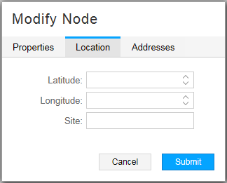
Enter latitude and longitude values using signed degrees format (DDD.dddd):
Latitudes range from -90 to 90.
Longitudes range from -180 to 180.
Positive values of latitude are north of the equator; negative values (precede with a minus sign) are south of the equator.
Positive longitudes are east of the Prime Meridian; negative values (precede with a minus sign) are west of the Prime Meridian.
Enter a site name in the Site field.
When provisioning diverse LSPs, NorthStar might return an error if the value you enter in the Site field contains special characters, depending on the version of Node.js in use. We recommend using alphanumeric characters only.
Figure 6 shows the Addresses tab of the Modify Node window.
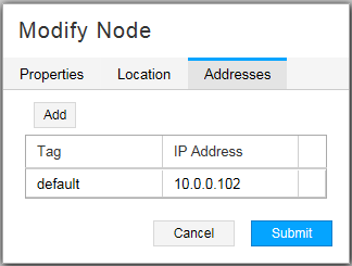
The NorthStar Controller supports using a secondary loopback address as the MPLS-TE destination address. In the Addresses tab of the Modify Node window, you have the option to add destination IP addresses in addition to the default IPv4 router ID address, and assign a descriptive tag to each. You can then specify a tag as the destination IP address when provisioning an LSP.
A secondary IP address must be configured on the router for the LSP to be provisioned correctly.
Click Add to create a new line where you can enter the IP address and the tag.
Click Submit to complete the node modification.
Actions Available for Links
For links, Add is a supported function. The Add Link window is shown in Figure 7.
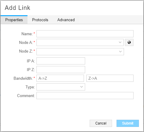
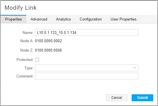
Delete is allowed as long as the prerequisites for link deletion have been met, as described earlier in this topic. Modify is available and is primarily used in support of the Multilayer feature. Sometimes, when interlayer links are initially loaded into the model, only the source is known. In those cases, you can select Node Z (the remote node name) from the drop-down menu, and enter IP Z (the corresponding IP link end on Node Z) to manually connect the Transport Layer to the IP Layer. You can also specify the Type of the link and add your comments for reference. On the Advance tab, you can specify Delay and Admin Weight values for the link. On the User Properties tab, you can add properties not already defined. The Properties tab of the Modify Link window is shown in Figure 8.
Actions Available for Tunnels
For tunnels, Add, Modify, and Delete are available functions for PCE-initiated tunnels.
Figure 9 shows the Provision LSP window.
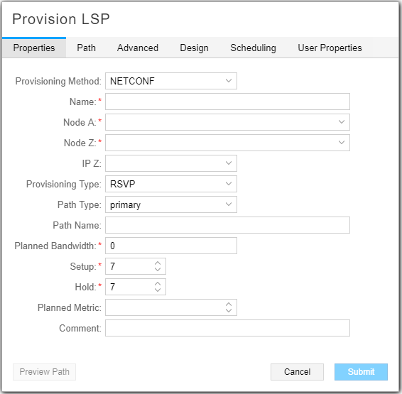
You can also reach the Provision LSP window from the Applications menu in the top menu bar by navigating to Applications>Provision LSP. See Provision LSPs for descriptions of the data entry fields in this window.
The Modify LSP window has the same data entry fields as the Provision LSP window (not all of which can be modified).
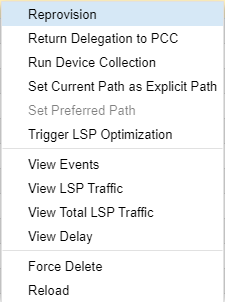
It can sometimes be necessary to remove LSPs from the topology when deletion requests have been rejected by the devices or when a deletion request cannot be sent to the device because the device is decommissioned. In that case, the Delete button at the bottom of the network information table does not work to delete the LSP. Instead, right-click the LSP row in the network information table (Tunnel tab) and select Force Delete. This option in the right-click drop-down menu is shown in Figure 10.
Actions Available for SRLGs
Shared Link Risk Group (SRLG) information can come from two sources:
BGP-LS
Transport controller
The information from these sources is merged and presented in the web UI. You can also Add, Modify, and Delete user-defined SRLGs.
Actions Available for Maintenance Events
Add, Modify, and Delete are available functions in the network information table for maintenance events. You can also reach the Add Maintenance Event window from the Applications menu in the top menu bar by navigating to Applications>Maintenance. See Maintenance Event Overview for descriptions of the data entry fields in the Add Maintenance Event window.
The Modify Maintenance Event window contains the same fields as the Add Maintenance Event window.
You can access the Maintenance Event Simulation window by right-clicking in a maintenance event row and selecting Simulate.
Actions Available for Interfaces
Interfaces cannot be added, modified, or deleted from the network information table.
Actions Available for P2MP Groups
Add, Modify, and Delete are available functions in the network information table for P2MP groups. These functions are for P2MP groups only, not for sub-LSPs within a group. To modify or delete sub-LSPs, use the Tunnel tab.
See Provision and Manage P2MP Groups for descriptions of the data entry fields in the Add P2MP Group window.
Actions Available for Demands
The Demand tab displays:
LDP Forwarding Equivalent Class (FEC) data compiled as a result of LDP collection tasks. These demands can be added, modified, or deleted from the network information table. Demands are never automatically deleted. See LDP Traffic Collection for information about this data.
Demands resulting from the Netflow Collector, which you can add, modify, or delete. Demands are never automatically deleted. See Netflow Collector for more information about Netflow Collector data.