ON THIS PAGE
Segment Routing-Do Not Use
NorthStar Controller supports Source Packet Routing in Networking (SPRING), also known as segment routing. Starting with Junos OS Release 17.2R1, segment routing for IS-IS and OSPFv2 is supported on QFX5100 and QFX10000 switches. Starting with Junos OS Release 17.3R1, segment routing for IS-IS and OSPFv2 is supported on QFX5110 and QFX5200 switches. See the Junos OS documentation for information about segment routing concepts and support on Juniper devices running Junos OS.
Junos OS Release 17.2R1 or later is required to utilize NorthStar Controller SPRING features. However, NorthStar Controller does not report the correct record route object (RRO) in the web UI and via the REST API when routers are configured with Junos OS Release 17.2R1. Instead of showing a list of link adjacency SIDs, the web UI and REST API report a list of “zero” labels. This issue has been fixed in Junos OS Releases 17.2.R1-S1 and 17.2R2, and later releases.
Some additional notes about segment routing (SR) LSP support:
-
NorthStar supports OSPF for SPRING as of NorthStar Release 5.0.0, using Junos OS Release 19.1 or later.
-
You must have Junos OS Release 19.1 or later to provision an SR LSP with a loose hop as the explicit path, together with routing method “RoutebyDevice”.
-
NorthStar diverse LSP and multiple LSP provisioning support segment routing. Select SR from the Provisioning Type drop-down menu on the Provision Diverse LSP or Provision Multiple LSPs window.
-
Maintenance events involving SR LSPs are supported for PCEP-based SR LSPs.
-
SR LSPs can be configured via NorthStar using either PCEP (real-time push model) or NETCONF (non-real-time pull model—LSP information is collected via periodic NETCONF device collection).
See Provision LSPs for full documentation of the Provision LSP window tabs. The following sections describe provisioning SR LSPs using NorthStar and viewing the SR LSP information in the NorthStar web UI.
Segment ID Labels
Adjacency segment ID (SID) labels (associated with links) and node SID labels (associated with nodes) can be displayed on the topology map.
You can use either BGP-LS peering or IGP adjacency from the virtual machine running Junos OS in the NorthStar Controller (JunosVM) to the network to acquire network topology. However, for SPRING information to be properly learned by NorthStar when using BGP-LS, the network should have RSVP enabled on the links and the TED database available in the network.
Starting
in Junos OS Release 19.4R1, you can configure Juniper Networks devices to advertise
selective traffic-engineering attributes without enabling RSVP for segment routing
and interior gateway protocol (IGP) deployments. Use the Junos command
protocols ospf traffic-engineering advertisement always to
configure this, so the TED can be populated properly without the need to enable
RSVP.
Junos OS Release 19.2R1-S1 also supports this configuration.
To display adjacency SID labels on the map:
-
Click the Tools (gear) icon (on the right of the topology map).
The Topology Settings page appears.
-
Click Links.
The links settings appears.
-
Select Show Label check box and from the drop-down menu select SID A::Z.
The adjacency SIDs are displayed on the map.
To view adjacency SID labels in the network information table, on the Link tab, click the down arrow besides any column heading and click Columns to display the full list of available columns. Then, click the check boxes beside SID A and SID Z.
An example topology map showing adjacency SID labels is shown in .
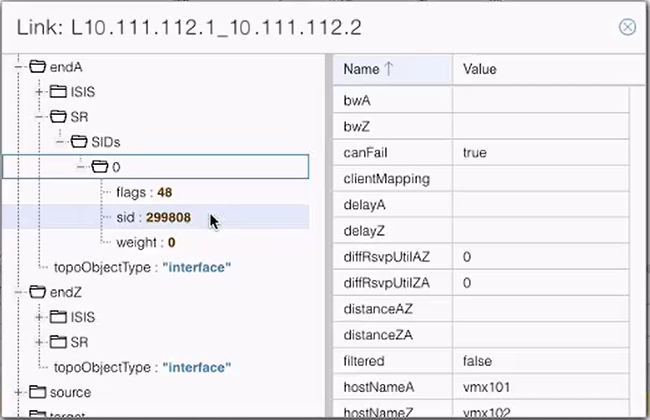
To display detailed information for a specific link (by double clicking the link in the topology map or in the network information table), you see an attribute folder (named SR) for both endA and endZ. You can drill down to display attributes for each SID as shown in Topology Map Showing Adjacency SID Labels. The endA folder contains details related to node A and endZ folder contains details related to node Z. At present, only IPv4 SIDs are supported, and NorthStar Controller only supports one adjacency SID per interface.
You can display adjacency SID labels on the map. On the right side of the topology window is a menu bar offering various topology settings. Click the Tools (gear-shaped) icon to bring up the Topology Settings window and select Links. Click the check box for Show Label and select SID A::Z from the corresponding drop-down menu. An example topology map showing adjacency SID labels is shown in #segment-routing__fig-topo-with-sids

To view adjacency SID labels in the network information table, click the down arrow beside any column heading under the Link tab, and click Columns to display the full list of available columns. Click the check boxes beside SID A and SID Z.
When you display the detailed information for a specific link (by double clicking the link in the map or in the network information table), you see an attribute folder for both endA and endZ called SR. You can drill down to display attributes for each SID as shown in #segment-routing__fig-new-sr-attribute-folder. At present, only IPv4 SIDs are supported, and only one per interface.
Node SID labels are displayed a little differently because the value of the label depends on the perspective of the node assigning it. A node might be given different node SID labels based on the perspective of the assigning node. To display node SID labels on the topology map, specify the perspective by right-clicking on a node and selecting Node SIDs from selected node. The node SID labels are then assigned from the perspective of that selected node.
For example, #segment-routing__fig-node-sid-vmx101 shows a topology displaying the SID node labels from the perspective of node vmx101. Note that the node SID label for node vmx106 is 1106.
If you right-click on node vmx104 and select Node SIDs from selected node, the node SID labels on the topology change to reflect the perspective of node vmx104 as shown in #segment-routing__fig-node-sid-vmx104. Note that the node SID label for node vmx106 is now 4106.
The selected node does not display a node SID label for itself. Any other nodes in the topology map that do not display a node SID label do not have the segment routing protocol configured.
Node SID information is not available in the network information table.
Create SR LSPs
An SR LSP is a label stack that consists of a list of adjacency SID labels, node SID labels, or a combination of both the labels.
To create an SR LSP:
-
Navigate to the Tunnel tab in the network information table and click Add at the bottom of the table.
The Provision LSP window (Properties tab) appears.
-
From the Provisioning Method drop-down menu, select either PCEP or NETCONF.
-
PCEP SR LSPs are PCE-initiated and the associated configuration statements do not appear in the router's configuration file. The advantage of PCEP is that LSP information is provided to NorthStar in real time, so changes in path or state are reflected in the NorthStar UI immediately.
-
NETCONF SR LSPs are statically provisioned and the associated configuration statements do appear in the router configuration file. While SR LSPs can be provisioned via NETCONF, they can also be learned via either PCEP or NETCONF. In Junos OS Release 18.2 R1, PCEP reporting is limited. The alternative is to learn about the details of the NETCONF-provisioned SR LSPs by way of Device Collection configuration parsing in NorthStar.If you opt to use this method for SR LSP provisioning, be aware that because the primary path details come from device collection configuration parsing, updates are not provided to NorthStar in real time, and NorthStar reports the operation status for these LSPs as Unknown.
In order for the configuration statements to be included in the router configuration file, SR LSPs must be configured in NorthStar via NETCONF.
Note:In Junos OS Release 18.2 R1, PCEP reporting is limited. The alternative is to learn
about the details of the NETCONF-provisioned SR LSPs by way of Device Collection
configuration parsing in NorthStar. If you opt to use this method for SR LSP provisioning, be
aware that because the primary path details come from device collection configuration
parsing, updates are not provided to NorthStar in real time, and NorthStar reports the
operation status for these LSPs as Unknown.
-
-
Configure the Name, Node A, and Node Z fields.
-
From the Provisioning Type drop-down menu, select SR.
-
If you selected NETCONF SR LSP as the provisioning (not applicable to PCEP), you can specify a binding SID label value in the Binding SID field on the Advanced tab. See the Binding SID section for more information.
-
On the Design tab, select the routing method from the Routing Method drop-down menu, typically either routeByDevice (which means that the router computes some of the path) or default (NorthStar computes the path). The oter routing method options are adminWeight, delay, constant, distance, ISIS, and OSPF.
-
On the Path tab, you can specify any specific hops you want in the path, including private forwarding adjacency links generated by the provisioning of binding SID SR LSP pairs. See the Binding SID section for more information.
-
Click Submit.
The provisioning request then enters the Work Order Management process.
-
For both PCEP and NETCONF provisioned SR LSPs, once the work order is activated, the new path is highlighted in the topology map.
-
For NETCONF provisioned SR LSPs, once the work order is activated, the corresponding configuration statements appear in the router configuration file.
-
Once the SR LSPs are provisioned, ensure the LSP status is active in the network information table and that the traffic is routed over the desired path.
Viewing the SR Path
To view the details of the SR path, do one of the following:
-
The IP address and the SID are the two parts of the explicit route. The IP address part is displayed in the ERO column and the SID is displayed in the Record Route column in the network information table.
-
Double-click on a tunnel entry in the network information table and drill down into the liveProperties to see the details of the ERO.
-
Use Junos OS show commands on the router. Some examples are:
-
show spring-traffic-engineering lsp name
                                        lsp-name detail
to display the LSP status and SID labels. -
show route table inet.3to display the mapping of traffic destinations with SPRING LSPs.
-
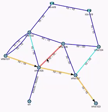
If a link (in a path) is used in both directions, it is highlighted in a different color in the topology, and does not have arrowheads to indicate direction. Figure 6 shows an example in which the link (highlighted in red) between vmx105 and vmx106 is used in both directions.
Binding SID
When you provision a pair of binding SID SR LSPs (one going from A to Z and one for the return path from Z to A), a private forwarding adjacency is automatically generated. These adjacencies are named with a specific format, with three sections, separated by colons. For example, binding:0110.0000.0105:privatefa57.
-
The names all start with “binding” followed by a colon.
-
The center section is the name of the originating node, followed by a colon (0110.0000.0105: in this example).
-
The last section is the name you specified for the binding SID SR LSP in the Name field on the Properties tab of the Provision LSP window (privatefa57 in this example). This name must be the same for the binding SID SR LSPs in both directions, to ensure they can be properly matched, creating the corresponding private forwarding adjacency link.
In the topology map, you can opt to display private forwarding adjacency links or not. In the left pane drop-down menu, select Types and then select or deselect the check box for privateForwardingAdjacency under Link Types as shown in #segment-routing__fig-types-forw-adj-binding-sid. When selected, the adjacencies display as dotted lines on the topology map as shown in #segment-routing__fig-forw-adj-binding-sid.
You can tunnel a non-binding SID SR LSP over a binding SID SR LSP, thereby reducing the number of labels in the label stack (private forwarding adjacency labels can represent multiple hops in the path). An example is shown in #segment-routing__fig-label-stack-ex.
Tunneling a binding SID SR LSP over another binding SID SR LSP is not supported.
In this display, you can see the logical path (traced in amber) of the SR LSP as it goes from vmx101 to vmx105, to vmx107 by way of a private forwarding adjacency link, and finally to vmx103. You can also see (traced in pink) the path of the private forwarding adjacency link of the binding SID SR LSP. The Record Route column in the network information tunnel shows a label stack with three labels. The second label of the three is the private forwarding adjacency link. Without that adjacency link, the label stack would have required six labels to define the same path.
Path highlighting for an SR LSP in a network that has two adjacency SIDs per interface is not supported.
To provision a pair of binding SID SR LSPs, use the procedure for NETCONF SR LSP provisioning, plus:
-
On the Provision LSP window Advanced tab, populate the Binding SID field with a numerical binding SID label value of your choice from the static label range of 1000000 to 1048575. This value then becomes the label that represents the path defined by the hops you specify on the Path tab (the hops that make up the private forwarding adjacency link).
Note:At this time, NorthStar does not support binding SID label allocation nor collision detection. Note that Junos OS has built-in collision detection, so that if the binding SID label specified is outside the allowed range of 1000000 to 1048575, the router does not allow the configuration to commit. Correspondingly, the Controller Status in the Tunnel tab of the network information table shows the usual indication of FAILED(NS_ERR_INVALID_CONFIG).
-
On the Design tab, select the routing method, default for example.
-
On the Path tab, select the hops in the path.
-
Provision a second binding SID SR LSP in the opposite direction, using the same LSP name as the first LSP in the pair. The binding SID label value can also be the same as in the first LSP in the pair, but it is not required that it be the same.
When the binding SID SR LSP pair is provisioned, the private forwarding adjacency link is automatically created, and can then be selected as a destination when you designate hops for a non-binding SID SR LSP. Use show commands on the router to confirm that the LSP pair has been pushed to the router configuration.
Maximum SID Depth (MSD)
To avoid encountering an equipment limitation on the maximum SID depth (MSD), you can use the Routing Method drop-down menu in the Provision LSP window (Design tab) to select routeByDevice as shown in #segment-routing__fig-routebypcc-selection. This option allows the router to control part of the routing, so fewer labels need to be explicitly specified.
routeByDevice is to be used when you want to create an SR LSP with Node SID.
When provisioning via PCEP, a symptom of encountering the MSD limitation when you are not using routeByDevice is that although a row for the new LSP is added to the network information table, the Op Status is listed as Unknown and the Controller Status is listed as Reschedule in x minutes.
Provisioning of an SR LSP can include hop information that somewhat influences the routing. In the Provision LSP window, select the Path tab. There, you can select hops up to the MSD hop limitation that is imposed on the ingress router, and specify Strict or Loose adherence.
PCEP RoutebyDevice Example
In #segment-routing__fig-ecmp-paths-with-routebypcc, the routing paths highlighted are the equal cost paths for the t2 LSP.
For t2 in this example:
-
Node A is vmx101 and Node Z is vmx104.
-
The provisioning type is SR, designated in the Properties tab of the Provision LSP window.
-
The routing method is routeByDevice, designated in the Design tab of the Provision LSP window. The highlighting of the equal cost paths can only be viewed in the topology if the routing is being done by the PCC.
The mandatory transit router can be part of the generated ERO using the adjacency SID passing through that transit router. However, specifying a mandatory transit router usually increases the label stack depth, violating the MSD. In that case, you can try using the routeByDevice method. To specify a mandatory transit router using Node SID, select the routing method as routeByDevice (Design tab), and specify the loopback of the mandatory transit router as loose hop (Path tab).
A possible downside to using routeByDevice is that other constraints you impose on the LSP links (bandwidth, coloring, and so on) cannot be guaranteed. The NorthStar Controller does not provision the LSP if it sees that the constraints cannot be met. But if the information available indicates that the constraints can be met, the NorthStar Controller provisions the LSP even though those constraints are not guaranteed. Turning on the path optimization timer enables NorthStar to periodically check the constraints.
If the NorthStar Controller later learns (during the execution of an optimization request, for example) that the constraints are no longer being met, it will try to reroute the tunnel by changing the first hop outgoing interface if a specific one was not configured. If that is not possible, the LSP remains in the network, even though constraints have been violated.
The Role of NETCONF Device Collection
SR LSPs provisioned using NETCONF can be learned either by PCEP or by device collection. When learned by device collection, the information is pulled in a non-real-time fashion only when collection tasks are run.
When you create your NETCONF device collection tasks, be sure you select the check box to collect configuration data. This is necessary for NorthStar to collect and parse the statements in the router configuration file, including those related to SR LSPs. See #segment-routing__fig-select-conf-collect-sr-lsp.
Automatic NETCONF collection is also performed every time an SR LSP is provisioned using NETCONF in the NorthStar UI.
Rerouting and Reprovisioning (PCEP-Provisioned SR LSPs)
For PCEP-provisioned SR LSPs, the router is only able to report on the operational status (Op Status in the network information table) of the first hop. After the first hop, the NorthStar Controller takes responsibility for monitoring the SID labels, and reporting on the operational status. If the labels change or disappear from the network, the NorthStar Controller tries to reroute and re-provision the LSPs that are in a non-operational state.
If NorthStar is not able to find an alternative routing path that complies with the constraints, the LSP is deleted from the network. These LSPs are not, however, deleted from the data model (they are deleted from the network, and persist in the data storage mechanism). The goal is to minimize traffic loss from non-viable SR LSPs by deleting them from the network. Op Status is listed as Unknown when an SR LSP is deleted, and the Controller Status is listed as No path found or Reschedule in x minutes.
You can mitigate the risk of traffic loss by creating a secondary path for the LSP with fewer or more relaxed constraints. If the NorthStar Controller learns that the original constraints are not being met, it first tries to reroute using the secondary path.
Although NorthStar permits adding a secondary path to an SR LSP, it is not provisioned as a secondary path to the PCC because the SR LSP protocol itself does not support secondary paths.
Allow Any SID at First Hop
By default,
NorthStar
Controller forces the first hop to be an adjacency SID, regardless
of the LSP configuration. You can alter this behavior by modifying an ingress node
to support any SID as the first hop. This is supported on PCC devices running Junos
OS Release 18.3 or later, and requires
that
the
Junos OS
command
set
                    protocols source-packet-routing
                inherit-label-nexthops
is configured.
To allow any SID at first hop:
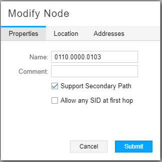
-
In the network information table, click the node you want to modify, then click Modify in the bottom tool bar.
The Modify Node pane appears.
-
On the Properties tab, select Allow any SID at first hop.
By default, the Allow any SID at first hop parameter is disabled (cleared). If enabled, NorthStar does not set an adjacency for newly signaled SR-LSPs (new LSPs or LSPs whose routing is changing).
-
Click Submit.
#segment-routing__fig-mod-node-allow-any-sid shows the Properties tab of the Modify Node window.
Delegating SR LSPs
As of NorthStar Release 6.0.0, you can delegate SR LSPs to NorthStar using the Configure LSP Delegation tool available under Applications in the UI. SR LSPs are included in the list of LSPs eligible for delegation in that tool. See Configure LSP Delegation for more information.
Colored SRTE Policies Using PCEP
Prior to NorthStar 6.2.0, you could apply the Color Community BGP attribute to SR LSPs created using NETCONF. Starting in NorthStar 6.2.0, this feature is also supported for LSPs provisioned using PCEP. To apply the color attribute, navigate to the Network Management > Provisioninig > Provision LSP > Advanced tab in the web UI and specify the color assignment in the Color Community field. This field is only available when the Provisioning Type is set to SR in the Properties tab.
You need Junos OS Release 20.4 or later running on a device to apply the Color Community BGP attribute to LSPs provisioned using PCEP.
Once a colored SR LSP is successfully provisioned, the corresponding configuration on the device indicates the color community. As shown in the following example, LSP-1 has a color community (<c>) of “123’.
[edit]
 northstar@vmx101# run show spring-traffic-engineering lsp

To                    State        LSPname
10.0.0.104-123<c>     Up           LSP-1
10.0.0.104            Down         LSP-2
10.0.0.104            Up           LSP-3
10.0.0.104            Up           LSP-4
For information about the assignment of color community in the context of NorthStar EPE, see NorthStar Egress Peer Engineering.
For background information about LSP coloring, see the Junos OS topic: Basic LSP Configuration.
On-Demand Next-Hop, Intra-Domain (Experimental)
This feature is for lab and demonstration purposes, only. We do not recommend using this feature for production networks.
The On-Demand Next-hop (ODN) in Junos OS provides the ability to dynamically create segment routing–traffic engineerring (SR–TE) LSPs when routes resolve over BGP next hops. The SR–TE LSPs can then be delegated and managed by NorthStar Controller. To use this feature, the device must be configured with a version of Junos 20.4 that supports SR ODN (e.g. JUNOS 20.4I-20200910).
You must configure the Juniper device for Junos OS to create the tunnels. The following example shows the prerequisite configuration:
set routing-options dynamic-tunnels odncf spring-te source-routing-path-template odnmytemplate
set routing-options dynamic-tunnels odncf spring-te destination-networks 10.0.0.11/32
set protocols source-packet-routing compute-profile test-compute-prof no-label-stack-compression
set protocols source-packet-routing compute-profile test-compute-prof maximum-computed-segment-lists 1
set protocols source-packet-routing source-routing-path-template odnmytemplate lsp-external-controller pccd
set protocols source-packet-routing source-routing-path-template odnmytemplate primary test-computer compute test-compute-prof
In the routing-options dynamic-tunnels configuration section, specify a template and the endpoint of the dynamic tunnels (the destination network). The destination network could be one device or multiple devices (indicated by the subnet). The template (odnmytemplate in the example) is specified under the protocols source-packet-routing source-routing-path-template. The device configuration also points to a compute profile which can include additional parameters.
To summarize, the configuration on the device establishes:
-
The source routing path template
-
The destination network
-
The compute profile
See your Junos OS documentation for general guidelines on the syntax and usage of these specific commands.
Once the dynamic LSPs are created by the router, run the show dynamic-tunnels
database command to view the new tunnel (see the example below).
Correspondingly, the dynamic tunnel will be displayed on the NorthStar Tunnel tab.
northstar@PE1# run show dynamic-tunnels database
*- Signal Tunnels #- PFE-down
Table: inet.3

Destination-network: 10.0.0.11/32

Tunnel to: 10.0.0.11/32
  Reference count: 1
  Next-hop type: spring-te
      10.0.0.11:dt-srte-odncf
      State: Established
To delegate an ODN LSP to NorthStar, configure the following statement on the Junos device:
set protocols source-packet-routing lsp-external-controller pccd
set protocols source-packet-routing source-routing-path-template odnmytemplate lsp-external-controller pccd
In the statement above, odnmytmeplate is the name of a particular template.