VPLS-LDP VPN
The VPLS-LDP VPN, based on the IETF Lasserre/Kompella draft, is implemented by Cisco and all other vendors except Juniper. To configure a VPLS-LDP VPN, perform the following steps:
- First identify, for the VPLS-LDP, a set of PEs with available PE-facing-CE interfaces that can be assigned as VPLS attachment circuits.
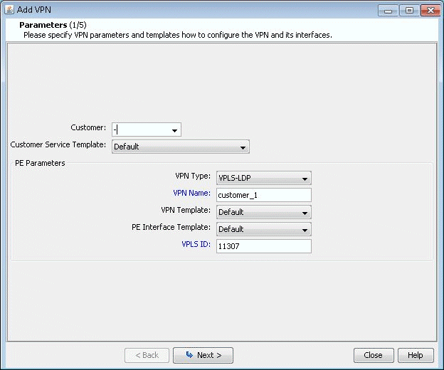
- Next, bring up the Add VPN window and select VPLS-LDP
VPN. In this example, we will configure a VPLS instance named
VPLS-LDP0.Figure 1: Creating a VPLS-LDP VPN
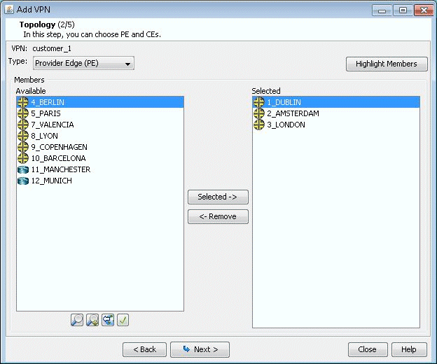
- Click on Next to take you to the screen to specify a VCID
and to select the PEs for the VPLS instance, as shown in the following
screen. If you prefer, you may select some or all the PEs in the PE
Selection tab in the next screen, as described in the next step. Click
on Next to continue.Figure 2: Select PEs and Specify a VCID
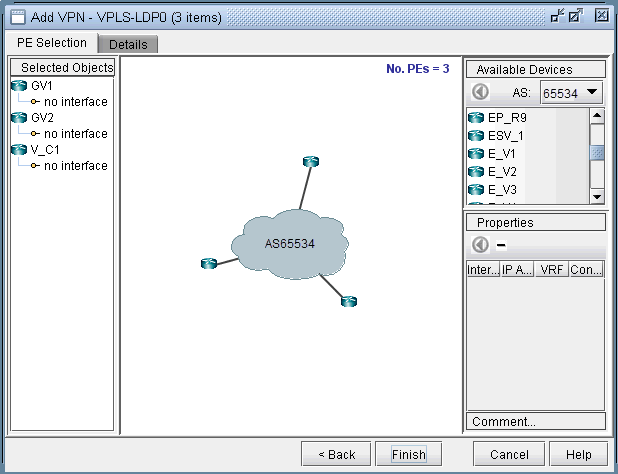
- As described in the previous step, you may select PEs in the PE Selection tab, as shown in the following screen.
If you have already selected all the PEs in the previous step, then
click on the Details tab to continue.Figure 3: Additional PEs may be select in the PE Selection tab
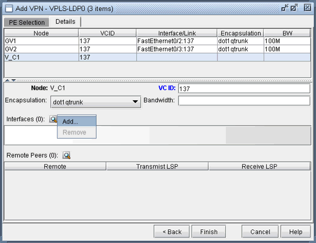
- Next, you are ready to configure the PE-facing-CE attachment
circuits; this includes specifying the interface and circuit ID, bandwidth,
and encapsulation.Figure 4: Configure VPLS-LDP Details
The encapsulation types for various vendors are:
Cisco: dot1qaccess, dot1qtunnel, dot1qtrunk.
Foundry: tagged, untagged.
Tellabs, Riverstone: tagged, untagged, q-in-q.
The following figures show how an interface is assigned: First, click on the magnifying glass next to Interfaces and choose Add. Then in the Select Interface window, pick an available interface. Finally, type in the VCID for the interface
Figure 5: Select an interface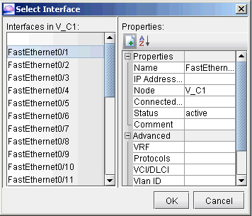 Figure 6: Assign the Circuit ID to the interface
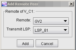
- Next, you will specify, in turn, each remote peer and
the transmit LSP used to reach the peer. Click on the magnifying glass
next to Remote Peers to bring up the Add Remote Peer window, where
you can choose the remote peer and the transmit LSP from the dropdown
selection menus.Figure 7: Configure PE peers
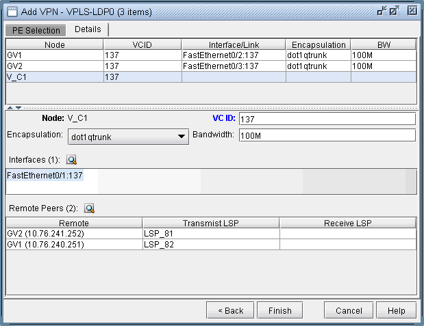
- The following figure shows the assignment details completed
for our VPLS instance, VPLS-LDP0. Click on Finish to add the VPLS
instance to the model.Figure 8: VPLS-LDP instance details configured
