Bandwidth Management
There are two methods for enabling NorthStar to control RSVP bandwidth reservations without the support of proprietary PCEP extensions on the PCC. Using these methods, NorthStar, not the PCC, makes bandwidth reservation decisions based on actual traffic. These methods are possible because NorthStar analytics gathers (via periodic SNMP polling or JTI telemetry streams) the traffic statistics necessary for NorthStar to make path-related decisions. Both methods are vendor-agnostic.
NorthStar does not support collection of SR-TE LSP statistics via SNMP, and therefore cannot support automatic bandwidth sizing on SR-TE LSPs where statistics are collected via SNMP.
Starting with NorthStar Release 5.0.0, you cannot enable bandwidth sizing in the Provision LSP window if the provisioning method is NETCONF.
Bandwidth Sizing
The following sections describe bandwidth sizing and how to use it.
- Bandwidth Sizing Overview
- Bandwidth Sizing on the PCS Versus Auto-Bandwidth on the PCC
- Bandwidth Sizing-Enabled LSPs
- Adding a Bandwidth Sizing Task
- Viewing LSP Statistics and Bandwidth
- Using Bandwidth Sizing Together with Zero Bandwidth Mode
Bandwidth Sizing Overview
NorthStar Controller can be configured to periodically compute a new planned bandwidth for each bandwidth sizing-enabled LSP based on aggregated LSP traffic statistics. NorthStar sends new planned bandwidth information to the NorthStar Path Computation Server (PCS) where the actual computation is done. The PCS determines, based on the new bandwidth requirements and the LSP bandwidth sizing parameters, whether it needs to provision the new planned bandwidth or not.
Only the bandwidth of PCE-initiated and PCC-delegated LSPs can be sized this way. PCC-controlled LSPs are not eligible.
For bandwidth sizing to occur, you must:
Enable NorthStar analytics
NorthStar supports bandwidth sizing for all PCE-initiated and PCC-delegated LSPs for which it can obtain LSP statistics, either via Juniper Telemetry Interface (JTI), or SNMP collection (scheduled via the Task Scheduler). This means that you must enable/use NorthStar analytics, and confirm that NorthStar is receiving traffic from the LSPs.
Configure PCE-initiated and PCC-delegated LSPs so their bandwidth sizing attribute is set to yes (bandwidth sizing enabled). LSPs without this setting are not sized.
Create and schedule a bandwidth sizing task in the Task Scheduler, as described later in this topic.
Bandwidth Sizing on the PCS Versus Auto-Bandwidth on the PCC
Bandwidth sizing can be confused with auto-bandwidth. Auto-bandwidth is configured on the router. NorthStar supports auto-bandwidth by responding to instructions from the router regarding bandwidth changes. Table 1 summarizes the differences between auto-bandwidth and bandwidth sizing.
Auto-Bandwidth |
Bandwidth Sizing |
|
|---|---|---|
Where configured |
Router (PCC) via a template |
NorthStar (PCS) via web UI or REST API |
Supported LSP types |
PCE-initiated PCC-delegated PCC-controlled RSVP |
PCE-initiated PCC-delegated Provisioning Method=PCEP Provisioning Type=RSVP SR-TE with Junos OS 19.2R1 or later |
Supported vendor types |
Juniper devices |
Vendor-agnostic |
Adjustment period |
Per-LSP |
One centralized schedule applies to all bandwidth sizing-enabled LSPs |
Bandwidth computations and bandwidth change decisions |
Done by the router (PCC) |
Done by NorthStar (PCS) |
Aggregation statistics options |
Average |
Average Max X Percentile (80, 90, 95, 99) |
Requires NorthStar Analytics? |
No |
Yes (to acquire LSP traffic statistics) |
Behavior if both are configured |
Auto-bandwidth overwrites bandwidth sizing and vice versa. For this reason, you should not have auto-bandwidth enabled for bandwidth sizing-enabled LSPs. Note:
For PCE-initiated LSPs, this means you must ensure that the name of the LSP does not match any configured label-switched path template that includes the auto-bandwidth parameter. For PCC-delegated LSPs, this means you must ensure that the auto-bandwidth parameter is not configured on the router. |
|
See NorthStar Controller Features Overview, Understanding the Behavior of Delegated Label-Switched Paths, and Creating Templates to Apply Attributes to PCE-Initiated Label-Switched Paths for more information about how NorthStar supports auto-bandwidth on the PCC.
Bandwidth Sizing-Enabled LSPs
Only bandwidth sizing-enabled LSPs are included in the re-computation of new planned bandwidths. When you add or modify an LSP, you must set the Bandwidth Sizing (yes/no) setting to yes to enable sizing.
Starting with NorthStar Release 5.0.0, you cannot enable Bandwidth Sizing if the provisioning method is NETCONF.
At the same time, you also set values for the following parameters:
Adjustment threshold (%)
This setting controls the sensitivity of the automatic bandwidth adjustment. The new planned bandwidth is only considered if it differs from the existing bandwidth by the value of this setting or more.
Minimum (planned) bandwidth
Maximum (planned) bandwidth
The minimum and maximum planned bandwidth values act as boundaries:
If the new planned bandwidth is greater than the maximum setting, NorthStar signals the LSP with the maximum bandwidth.
If the new planned bandwidth is less than the minimum setting, NorthStar signals the LSP with the minimum bandwidth.
If the new planned bandwidth falls in between the maximum and minimum settings, NorthStar signals the LSP with the new planned bandwidth.
Minimum variation threshold
This setting specifies the sensitivity of the automatic bandwidth adjustment when the new planned bandwidth is compared to the current planned bandwidth. The new planned bandwidth is only considered if the difference is greater than or equal to the value of this setting. Because it is not a percentage, this can be used to prevent small fluctuations from triggering unnecessary bandwidth changes.
If both the adjustment threshold and the minimum variation threshold are greater than zero, both settings are taken into consideration. In that case, the new planned bandwidth is considered if:
The percentage difference is greater than or equal to the adjustment threshold, and,
The actual difference is greater than or equal to the minimum variation.
These parameters are also described in the context of the Provision LSP window.
Adding a Bandwidth Sizing Task
The bandwidth sizing task periodically sends a new planned bandwidth for bandwidth sizing-enabled LSPs to the NorthStar PCS. The PCS determines whether it needs to provision the new planned bandwidth with a path that satisfies the new bandwidth requirement.
To schedule a bandwidth sizing task, navigate to Administration > Task Scheduler from the More Options menu.
Click Add in the upper right corner. The Create New Task window is displayed as shown in Figure 1.
Figure 1: Create New Task Window
Enter a name for the task, select Bandwidth Sizing from the Task Type drop-down menu, and click Next.
Select an aggregation statistics option from the drop-down menu shown in Figure 2.
Figure 2: Bandwidth Sizing Task, Step 2
The aggregation statistic works together with the task execution recurrence interval (the period of bandwidth adjustment) that you set up in the scheduling window. NorthStar aggregates the LSP traffic for the interval based on the aggregation statistic you select, and uses that information to calculate the new planned bandwidth. The options in the Aggregation Statistic drop-down menu are described in Table 2.
Table 2: Bandwidth Sizing Aggregation Statistics Options Aggregation Statistic
Description
80th, 90th, 95th, 99th Percentile
Aggregation is based on the selected percentile.
The ‘X’ percentile is the value at which ‘X’ percent of all the samples taken in the previous sampling period lie at or below the calculated value. For bandwidth sizing, the newly-calculated bandwidth value is taken as the ‘X’ percentile of the samples in the immediately-preceding bandwidth sizing interval.
Average
For each interval, the samples within that interval are averaged. If there are N samples for a particular interval, the result is the sum of all the sample values divided by N.
Max
For each interval, the maximum of the sample values within that interval is used.
Click Next to proceed to the scheduling parameters. The Create New Task - Schedule window is displayed as shown in Figure 3. You must schedule the task to repeat at a specific interval from a minimum of 15 minutes to a maximum of one day. The default interval is one hour.
Note:There is no per-LSP interval. The interval configured here applies to all LSPs for which bandwidth sizing is enabled.
Figure 3: Bandwidth Sizing Task, Scheduling
Click Submit to complete the addition of the new collection task and add it to the Task List. Click a completed task in the list to display the results in the lower portion of the window. There are three tabs in the results window: Summary, Status, and History.
Note:You can have only one bandwidth sizing task per NorthStar server. If you attempt to add a second, the system will prompt you to approve overwriting the first one.
-
If the bandwidth sizing scheduled task does not result in published statistics for all the bandwidth sizing-enabled LSPs, see the Troubleshooting the NorthStar Controller chapter for troubleshooting tips.
LSPs for which traffic statistics are not available for a specified duration will not be resized if the bandwidth sizing task is scheduled to consider the statistics collected in the specified duration. This is because the task cannot differentiate between no traffic and zero bandwidth traffic.
Viewing LSP Statistics and Bandwidth
In the network information table (Tunnel tab), you can add optional columns related to bandwidth sizing by hovering over any column heading and clicking the down arrow that appears. Select Columns and click the check boxes to add columns for bandwidth sizing parameters as shown in Figure 4.
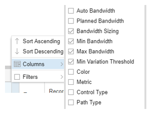
Once added, these columns display in the network information table the values of the parameters you configured for the bandwidth sizing-enabled LSPs.
You can view an LSP’s statistics and bandwidth in graphical form by right-clicking an LSP on the Tunnel tab of the network information table and selecting View LSP Traffic. An example of the display is shown in Figure 5.

This example shows the actual LSP traffic (blue line) as well as the signaled (configured) bandwidth (green line). The hide bandwidth/show bandwidth button allows you to toggle back and forth between including and not including the bandwidth in the display.
Logs related to bandwidth sizing are stored in /opt/northstar/logs and include:
bandwidth_sizing.log
pcs.log
Using Bandwidth Sizing Together with Zero Bandwidth Mode
In Administration > System Settings, there is an option to enable zero bandwidth signaling. By default, this functionality is disabled. When enabled, NorthStar can optimize resource utilization more effectively and more aggressively. This is true, with or without bandwidth sizing, and it affects all PCE-initiated and PCC-delegated LSPs, regardless of whether they are bandwidth sizing-enabled or not.
When zero bandwidth signaling is enabled and NorthStar is receiving traffic statistics for bandwidth sizing-enabled LSPs, NorthStar does the following at the end of the bandwidth adjustment period:
Computes the new planned bandwidth.
Computes a new path that satisfies the new planned bandwidth.
Updates the RSVP link utilization based on the new planned bandwidth and the new path.
Provisions the new path with zero bandwidth as opposed to provisioning with the new planned bandwidth.
Container LSPs
The following sections describe container LSPs and how to use them:
- Container LSPs Overview
- Container LSPs on the PCS Versus TE++ LSPs on the PCC
- Creating a Container LSP
- Creating a Container Normalization Task
- Viewing Container LSPs in the Network Information Table
Container LSPs Overview
A container LSP is a logical grouping of sub-LSPs that share the properties defined in the container. Container LSPs provide automatic adding or removing of sub-LSPs based on traffic statistics. This mitigates the difficulty of finding a single path large enough to accommodate a large bandwidth reservation. Using container LSPs involves:
Creating a container LSP from the network information table (Container LSP tab).
Creating a container normalization task using the Task Scheduler. During normalization, NorthStar calculates the number of sub-LSPs needed and if possible, provisions them.
Viewing container LSPs, as well as their sub-LSPs and traffic in the network information table.
Container LSPs on the PCS Versus TE++ LSPs on the PCC
Container LSPs are different from TE++ LSPs in ways that are important to understand. TE++ can only be configured on the router. NorthStar supports TE++ by responding to instructions from the router regarding the creation and deletion of sub-LSPs and the associated redistribution of bandwidth across the sub-LSPs. With container LSPs, NorthStar is doing the bandwidth computations and decision-making. Table 3 summarizes the differences between TE++ and container LSPs.
TE++ LSPs |
Container LSPs |
|
|---|---|---|
Where configured |
Router (PCC) via a template |
NorthStar (PCS) via web UI or REST API |
Supported LSP types |
PCC-delegated PCC-controlled |
PCE-initiated PCC-delegated |
Supported vendor types |
Juniper devices |
Vendor-agnostic |
Triggers for normalization to occur |
On a per-LSP basis, either:
|
One centralized normalization schedule applies to all container LSPs |
Bandwidth computations and bandwidth change decisions |
Done by the router (PCC) |
Done by NorthStar (PCS) |
Aggregation statistics options |
Average |
Average Max X Percentile (80, 90, 95, 99) |
Requires NorthStar Analytics? |
No |
Yes (to acquire LSP traffic statistics) |
Can both be configured simultaneously? |
We do not recommend allowing both the PCC and NorthStar to attempt normalization at the same time. |
|
See NorthStar Controller Features Overview for more information about TE++ LSPs.
Creating a Container LSP
To create a container LSP, start in the network information table. On the tabs bar, click the plus sign (+) and select Container LSP from the drop-down menu as shown in Figure 6.
When you launch the web UI, only the Node, Link, and Tunnel tabs are displayed by default; Container LSP is one of the tabs you can optionally display.
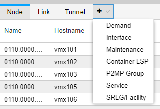
Click Add at the bottom of the table to open the Add Container window.
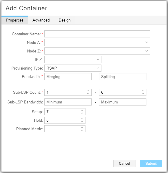
The fields specific to container LSPs are described in Table 4. The remaining fields are the same as for creating regular LSPs.
Field |
Description |
|---|---|
Name |
The name you assign to the container LSP is used as the base for automatic naming of the sub-LSPs that are created. |
Bandwidth (Merging-Splitting) |
Required. The container normalization task computes aggregated bandwidth for each container LSP and sends it to the Path Computation Server (PCS). Aggregate bandwidth thresholds are used to trigger merging or splitting of sub-LSPs during normalization.
Note:
Aggregation is based on the selected percentile [80th, 90th, 95th, 99th (X percentile)], or Average, or Max. For more information, see Table 2. |
Sub-LSP Count (Minimum-Maximum) |
Required. Minimum and maximum number of sub-LSPs that can be created in the container LSP. The default is 1-6. |
Sub-LSP Bandwidth (Minimum-Maximum) |
Minimum and Maximum bandwidth that can be signaled for the sub-LSPs during normalization or initialization, immediately followed by units (no space in between). Valid units are:
Examples: 50M, 1000b, 25g. If you enter a value without units, bps is applied. |
On the Advanced tab, you can opt to enable bandwidth sizing for a container LSP by selecting Bandwidth Sizing = yes and supplying values for the bandwidth sizing parameters. During normalization, NorthStar signals the sub-LSPs with equally divided container LSP aggregated bandwidth. However, the PCC might not forward traffic equally among the sub-LSPs. By also enabling bandwidth sizing for the container LSP, the sub-LSPs can be individually adjusted based on the actual traffic going over them.
Creating a Container Normalization Task
Use the Task Scheduler to enable periodic container LSP normalization. The container normalization task computes aggregated bandwidth for each container LSP and sends it to the NorthStar PCS. The PCS determines whether it needs to add or remove sub-LSPs belonging to the container LSP, based on the container’s new aggregated bandwidth.
To schedule a container normalization task, navigate to Administration > Task Scheduler from the More Options menu.
Click Add in the upper right corner. The Create New Task window is displayed as shown in Figure 8.
Figure 8: Create New Task Window
Enter a name for the task, select Container Normalization from the Task Type drop-down menu, and click Next.
Select an aggregation statistics option from the drop-down menu shown in Figure 9.
Figure 9: Container Normalization Task, Step 2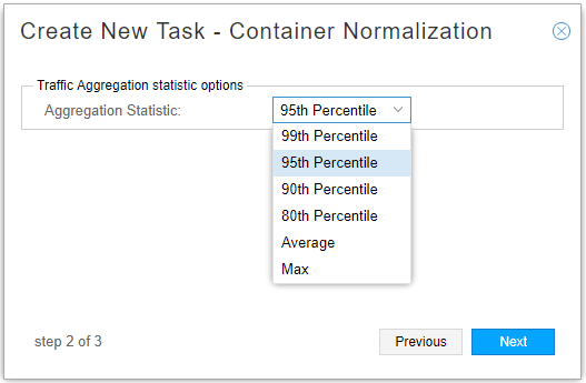
The aggregation statistic works together with the task execution recurrence interval that you will set up in the scheduling window, the same as it does for bandwidth sizing.
Click Next to proceed to the scheduling parameters which work just the same as for bandwidth sizing.
Click Submit to complete the addition of the new collection task and add it to the Task List. Click a completed task in the list to display the results in the lower portion of the window. There are three tabs in the results window: Summary, Status, and History.
Note:You can have only one container normalization task per NorthStar server. If you attempt to add a second, the system will prompt you to approve overwriting the first one.
Container LSPs for which traffic statistics are not available for a specified duration will not be normalized if the container normalization task is scheduled to consider the statistics collected in the specified duration. This is because the task cannot differentiate between no traffic and zero bandwidth traffic.
Viewing Container LSPs in the Network Information Table
The Container LSP tab is shown in Figure 10. You can add columns and filter the display in the usual ways. See Sorting and Filtering Options in the Network Information Table for more information.

Right-click a row in the Container LSP tab to select either View Sub LSPs or View Traffic. Each of these options opens a new tab in the network information table displaying the requested information. Figure 11 shows the right-click options in the Container LSP tab.
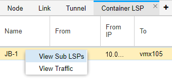
When you select View Sub LSPs, a new tab in the network information table opens displaying the sub-LSPs and their parameters. In the list of sub-LSPs, you have all the display options normally available on the Tunnel tab. See Network Information Table Overview for more information. Figure 12 shows an example of a sub-LSPs tab in the network information table.

The sub-LSP tab in the network information table is for display purposes only; you cannot perform Add, Modify, or Delete functions from there.
The sub-LSPs are also displayed in the Tunnel tab. The Container column (optionally displayed) identifies them as belonging to a container LSP. Figure 13 shows sub-LSPs in the Tunnel tab.

When you right-click a row in the Container LSP tab and select View Traffic, a new tab opens in the network information table displaying the traffic for the container LSP.Figure 14 shows an example of the View Traffic tab.

Logs related to container LSPs are stored in /opt/northstar/logs and include:
container_lsp.log
pcs.log
Bandwidth Sizing and Container LSP Support for SR-TE LSPs
NorthStar supports bandwidth sizing and container LSPs for SR-TE LSPs. Since the controller needs to calculate the aggregate LSP utilization of all auto bandwidth LSPs, this feature is supported only on LSP types that provide telemetry statistics. At this time, only PCE-initiated SR-TE LSPs are supported, requiring JUNOS version 19.2 and later.
The following additional limitations apply:
Only a global adjustment period and aggregation function is supported. Per-LSP adjustment period and/or aggregation function is not supported.
LSPs provisioned via NETCONF that are not delegated to the controller require a config commit to modify LSP attributes. Currently, NorthStar doesn’t perform such changes without user approval and, therefore, managing these kinds of LSPs is not supported. Whenever NorthStar adds support for automatic modification of NETCONF/PCC-controlled LSPs, this feature will be re-qualified for that scenario.
There is additional configuration required on the router to enable collection of segment routing data:
set services analytics sensor sr-te-tunnels server-name ns
set services analytics sensor sr-te-tunnels export-name ns
set services analytics sensor sr-te-tunnels resource /junos/services/segment-routing/traffic-engineering/tunnel/ingress/usage/
For more information about configuring the router for data collection, see Configuring Routers to Send JTI Telemetry Data and RPM Statistics to the Data Collectors in the NorthStar Controller Getting Started Guide.
