Map Elements
The network elements you can view on the topology map and customize in the left pane include nodes/groups, links, and facilities. Nodes and links you click in the left pane are highlighted in the topology map. Facilities are sets of nodes and links that are likely to fail together.
Network Elements > Nodes
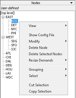
When this option is selected, the groups/nodes in the network are displayed in a tree view in the left pane. Selecting a node or collapsed group in the list highlights it on the map display. The groups, if defined in the network, are displayed with group elements indented underneath. To expand or collapse a group, click on the hinge icon to the left of it. You can add an element into a group by selecting the element name, dragging it and dropping it over the group’s name. Figure 1 shows the nodes/groups.

Network Elements > Links
When selected from the drop-down menu, this function displays all links associated with the protocol selected in the Subviews > Protocols menu. For example, if you select Frame-Relay protocol in the Subviews > Protocols menus, then the Links list displays only the links associate with Frame Relay.
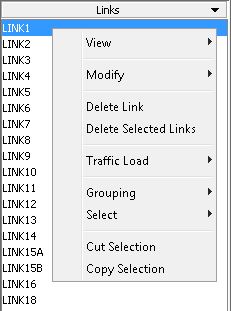
The link names are displayed in a list view in the left pane. Selecting a link name in the list highlights it in the topology window. Clicking on the links on the topology map highlighs them on the links list. Figure 2 shows an example of the links list.

Network Elements > Facilities
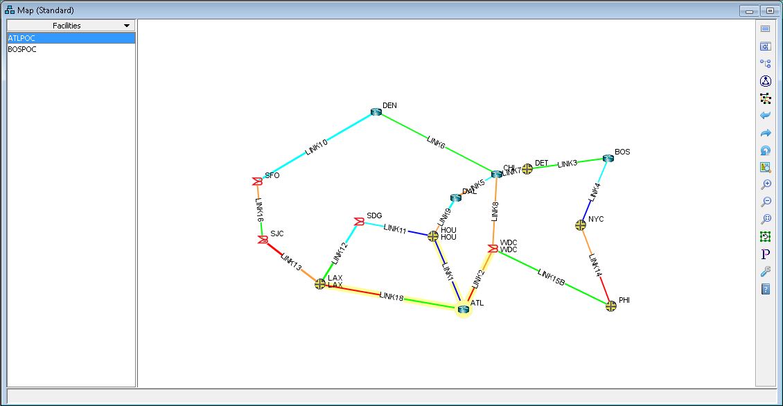
A facility is a group of links and/or nodes that are likely to fail together. It is used in failure simulations where accurate modeling requires the simultaneous failure of specific links and/or nodes. For instance, if several links travel over the same fiber, a fiber cut will break all of them at once. In this case, one can define a facility to represent the SRLG (Shared Risk Link Group) containing those links. Another example is the set of switches on one floor of a large data center, together with all the links going into or out of that floor.
Figure 3 shows an example of a facilities list in the left pane.

