Segment Routing Overview
Paragon Pathfinder supports a source-based routing technique that is known as Source Packet Routing in Networking (SPRING), also known as segment routing. In segment routing, an ingress router steers a packet through explicit paths in the network and doesn't rely on the transit nodes in the network to determine the path.
You can configure these explicit paths by adding a segment routing tunnel. See About the Tunnel Tab for information about how to add single, diverse, and multiple segment routing tunnels.
You can configure SPRING features on Juniper devices which run Junos OS Release 17.2R1 or later, and other vendor devices that support segment routing. Paragon Pathfinder supports both IS-IS and OSPF as the interior gateway protocols (IGPs) in the network for segment routing.
See the Junos OS documentation for details on segment routing concepts and support on Juniper devices which run Junos OS.
The following sections explain segment routing behavior in Paragon Pathfinder.
Segment Identifiers (SIDs)
Paragon Pathfinder compiles a set of paths that satisfy a policy into SIDs. These paths are prepended to a packet as instructions. The SIDs denote paths to nodes in a network. The nodes execute the instructions that are specified in the SID lists.
You can define the hops in a policy for a segment routing tunnel path in the Path tab that is displayed when you add or modify the tunnel. To define the hops, specify the sequence of nodes, links and groups of nodes that you want the path to traverse. The paths that satisfy your path policy will also satisfy your other requirements such as delay, bandwidth, and so on. Therefore, the result of segment routing path computation is a list of SIDs that instruct the network to implement paths that satisfy your policy. However, the SID list might not align exactly with the hops that are specified in the path policy.
Currently, Paragon Pathfinder supports node SIDs (associated with nodes), adjacency SIDs (associated with links), binding SIDs (associated with tunnels), and anycast SIDs (associated with anycast groups).
Currently, Paragon Pathfinder does not support binding SIDs and anycast SIDs for SRv6 tunnels.
If both a node SID and an anycast SID are available for path computation, the Path Computation Server implements the paths that satisfy your policy as follows to route traffic according to the path policy:
- The Path Computation Server uses the anycast SID instead of the node SID if PCEP is used as the provisioning method.
- The Path Computation Server uses the node SID instead of the anycast SID if NETCONF is used as the provisioning method.
To view the SIDs in the GUI, do the following:
-
Adjacency SID labels:
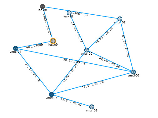
- To view segment routing-MPLS adjacency SID labels in the topology map, right-click anywhere on the blank space in the map. From the list that appears, select Link Label and then, select SID A::Z. To view SRv6 SID labels for links on the map, select Link Label and then, select SRv6 SID Function A::Z.
-
In the network information table, the Link tab displays the segment routing-MPLS SID labels for links in the SID A and SID Z columns. The SRv6 SID labels are displayed in the SRv6 SID A and SRv6 SID Z columns.
Figure 1 shows an example topology map with segment routing-MPLS SID labels for links.
To view the attributes of each SID for a specific link, select a link in the Link tab. Click the Details icon that appears when you hover over the link or select More > Show Detail. In the Link - Link Name page that appears, navigate to Details tab > endA (or endZ) > Protocols > SR > SIDs [n].
Note:Currently, Paragon Pathfinder supports only one segment routing-MPLS SID and one SRv6 SID per interface.
Figure 1: Adjacency SID Labels
-
Node SID labels—In the network information table, the Node tab displays the segment routing-MPLS SID labels for nodes in the SID column and the SRv6 SID labels in the SRv6 SID column. Also, you can view the segment routing-MPLS SID labels In the topology map. The SRv6 SID labels are, however, not displayed on the topology map.
Note:You can view the SID labels only when the segment routing global block (SRGB) value is in the same range for all the nodes in the network.
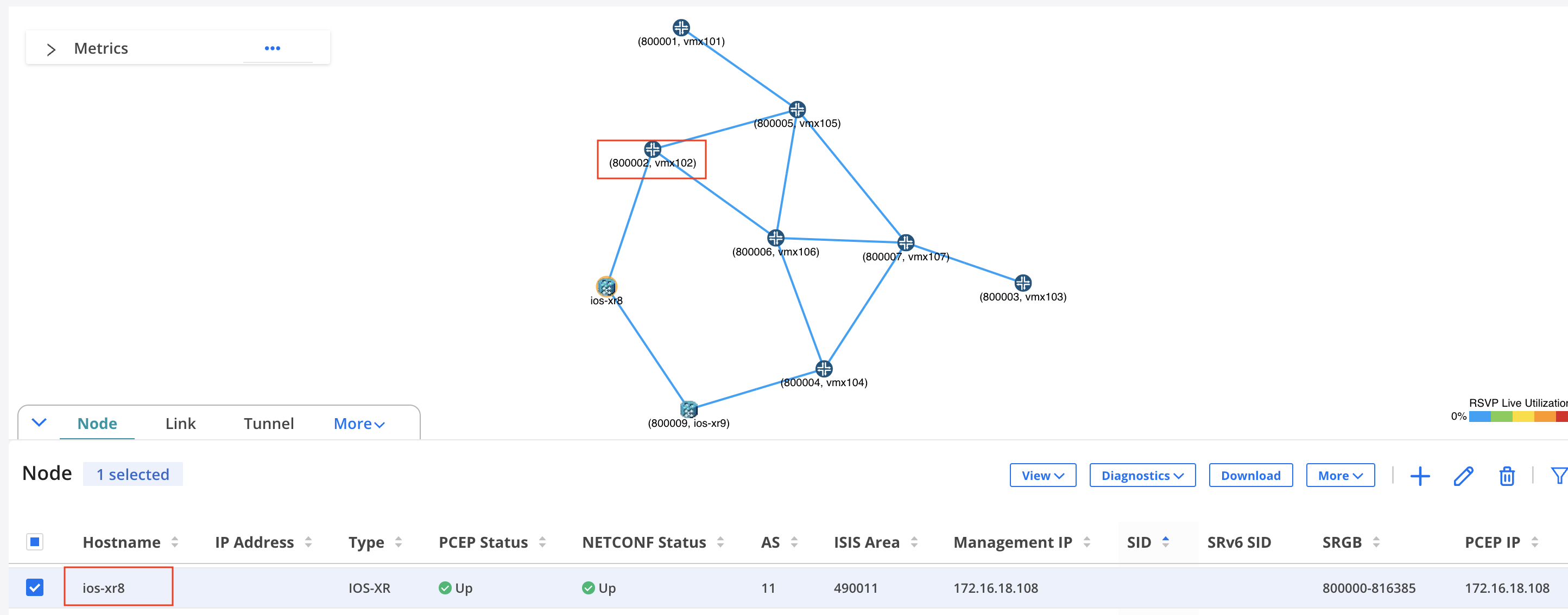
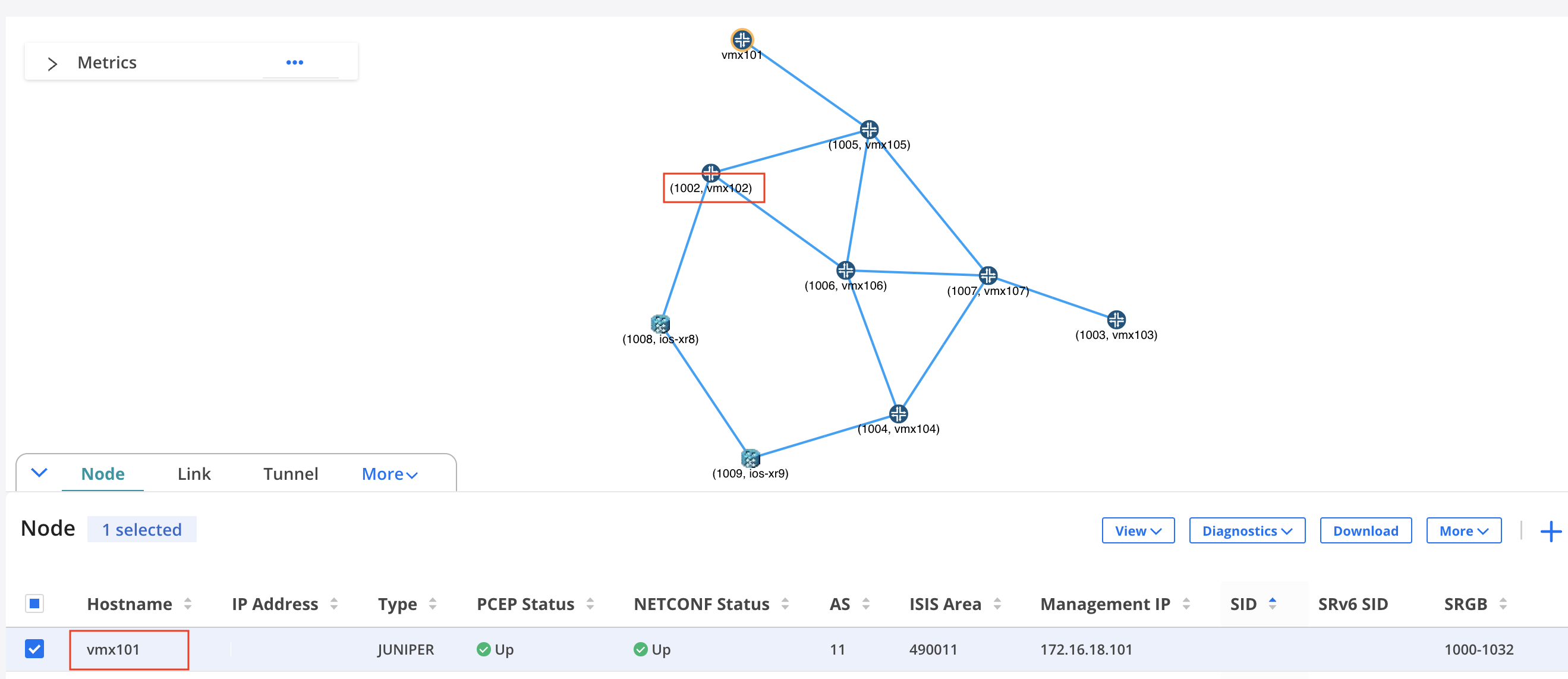
To view the node SIDs of other nodes from the perspective of a particular node, select the node in the network information table and click View > Node SIDs from Selected Node. The node SIDs of the nodes are displayed in the topology map from the perspective of the selected node. For example, Figure 2 shows the node SIDs of the nodes as viewed from the perspective of node ios-xr8, while Figure 3 shows the node SIDs as viewed from the perspective of node vmx101. A node can have different node SID values based on the perspective of a particular node. For example, from the perspective of node ios-xr8, the node SID for node vmx102 is 80002, whereas, from the perspective of node vmx101, the node SID for node vmx102 is 1002, as highlighted in Figure 2 and Figure 3.
Figure 2: Node SIDs as Viewed from ios-xr8 Figure 3: Node SIDs as Viewed from vmx101
- Anycast SID labels—In the network information table, the Anycast Group tab displays the anycast SID labels for segment routing-MPLS tunnels as the Index value in the SR column.
- Binding SID labels—In the network information table, the Tunnel tab displays the SID labels for binding segment routing-MPLS tunnels in the BSID column. The Link tab displays the SID labels in the SID A and SID Z columns.
Binding SIDs
You can provision a pair of binding SID segment routing-MPLS tunnels (one going from A to Z and one for the return path from Z to A) with NETCONF as the provisioning method. See Add a Single Tunnel for details on adding a tunnel. When the tunnels are provisioned, a private forwarding adjacency is automatically created. The names of these adjacencies are in a specific format, with three sections, separated by colons. For example, binding:0110.0000.0105:privatefa57.
- The names all start with “binding” followed by a colon.
-
The center section is the name of the originating node, followed by a colon (0110.0000.0105: in this example).
-
The last section is the name you specified for the binding SID segment routing tunnel in the Name field in the Properties tab of the Add Tunnel page (privatefa57 in this example).
You can tunnel only a non-binding SID segment routing tunnel over a binding SID segment routing tunnel (and vice versa). The binding reduces the number of labels in the label stack (private forwarding adjacency labels can represent multiple hops in the path).
Currently, Paragon Pathfinder does not support binding SID label allocation or collision detection. Junos OS has built-in collision detection. Thus, if the binding SID label specified is outside the allowed range of 1000000 through 1048575, Junos OS does not allow the configuration to commit. Correspondingly, the Controller Status in the Tunnel tab of the network information table displays FAILED(NS_ERR_INVALID_CONFIG).
To add a pair of binding SID segment routing tunnels, provision a second binding SID segment routing tunnel in the direction opposite to the first tunnel. You must use the same tunnel name as the first tunnel in the pair to ensure that the tunnels can be properly matched. The corresponding private forwarding adjacency link is automatically created when the tunnel pair is provisioned. The binding SID label value can also be the same as in the first tunnel in the pair, but it is not mandatory.
The private forwarding adjacency link can then be selected as a destination when you designate hops for a non-binding SID segment routing tunnel. Use show commands on the router to confirm that the tunnel pair is pushed to the router configuration.
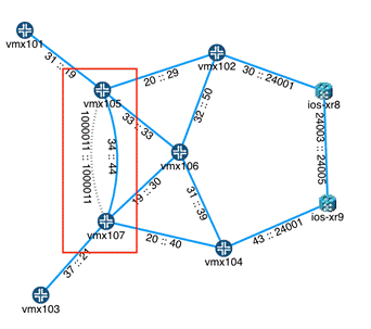
When you select a binding SID segment routing tunnel in the network information table, the corresponding private forwarding adjacency links are displayed as dotted lines in the topology map as shown in Figure 4.

Maximum SID Depth (MSD)
When the controller computes the segment routing paths, it must learn the MSD that it can impose at each node that corresponds to a segment routing path such that the SID stack depth value of the computed path does not exceed the number of SIDs imposed by the node.
To avoid an equipment limitation on the MSD, you can select RouteByDevice as the routing method when you add the segment routing tunnel with node SIDs. This option enables the router to control a part of the routing, so fewer labels need to be explicitly specified.
When you add a segment routing tunnel, a symptom of encountering the MSD limitation when you are not using routeByDevice is that although a row for the new tunnel is added in the network information table, the Op Status is displayed as Unknown and the Controller Status is displayed as Reschedule in x Minutes. No tunnel is created to forward the traffic. Thus, the traffic is forwarded as per the shortest path in the routing table for non-engineered traffic. To resolve this issue, you must request parameters (such as different hops) for the tunnel so that Paragon Pathfinder computes a path that does not violate the MSD of routers in the path. Alternatively, configure some tunnels with binding SIDs to create forwarding adjacencies so that Paragon Pathfinder can specify a binding SID in the SID list.
The hop information that you specify in the Path tab when you add a segment routing tunnel influences the routing. You can select hops up to the MSD hop limitation that is imposed on the ingress router, and specify Strict or Loose adherence. If you specify the hop as strict, the tunnel must take a direct path (with only the links and nodes that you specify for the path) from the previous router to this router. If you specify the hop as loose, the tunnel can take any path to reach this router; the PCE chooses the best path.
Rerouting and Reprovisioning
For PCEP-provisioned segment routing tunnels, the router is able to report the operational status of only the first hop. The Op Status column in the network information table displays the operational status. After the first hop, the controller takes responsibility for monitoring the SID labels, and for reporting the operational status. If the labels change or disappear from the network, the controller tries to reroute and re-provision the tunnels that are in a non-operational state.
If the controller cannot find an alternative routing path that complies with the constraints, the tunnel is deleted from the network. However, these tunnels are not deleted from the data model (the tunnels persist in the data storage mechanism). The goal is to minimize traffic loss from non-viable segment routing tunnels by deleting the tunnels from the network. When a segment routing tunnel is deleted, the Op Status column displays the status as Unknown. The Controller Status column displays the status as No path found or Reschedule in x Minutes.
You can mitigate the risk of traffic loss by creating a secondary path for the tunnel with fewer or more relaxed constraints. If the tunnel does not meet the original constraints, the controller first tries to reroute using the secondary path. If the rerouting works, the tunnel remains Up and is not deleted.
The controller permits adding a secondary path to a segment routing tunnel. However, it is not provisioned as a secondary path to the PCC because the segment routing tunnel protocol does not support secondary paths.
If you are creating a segment routing tunnel by using REST APIs, you can set the rerouting behavior of the tunnel to noRerouting. The segment routing Path Computation Server brings down the segment routing tunnel if topology changes cause traffic in the tunnel to deviate from the path it was originally provisioned on. If noRerouting is not specified (that is rerouting is allowed), the Path Computation Server computes a new path that complies with the user-defined path policy when the network topology changes. When the Path Computation Server has an option to use both node SIDs and anycast SIDs for implementing a path policy, the Path Computation Server uses SIDs as follows:
- If noRerouting is specified, node SIDs are used for implementing the path policy.
-
If rerouting is allowed, anycast SIDs are used for implementing the path policy. When the topology changes, the existing SID list can still implement a path policy by shifting the tunnel from one node in the anycast group to another node in the anycast group.
On-Demand Next-Hop, Intra-Domain (Experimental Feature)
This feature is for lab and demonstration purposes only. We do not recommend using this feature for production networks.
The On-Demand Next-hop (ODN) feature enables the controller to dynamically create segment routing–traffic engineering (SR–TE) tunnels when routes resolve over BGP next hops. The SR–TE tunnels can then be delegated and managed by the Path Computation Element (PCE). To use this feature, configure the device with a recent version of Junos OS 20.4 or later that supports segment routing ODN (for example, Junos 20.4I-20200910).
You must configure the Junos OS devices to create the tunnels. The following example shows the prerequisite configuration:
set routing-options dynamic-tunnels odncf spring-te source-routing-path-template
odnmytemplate
set routing-options dynamic-tunnels odncf spring-te destination-networks 10.0.0.11/32
set protocols source-packet-routing compute-profile test-compute-prof
no-label-stack-compression
set protocols source-packet-routing compute-profile test-compute-prof
maximum-computed-segment-lists 1
set protocols source-packet-routing source-routing-path-template odnmytemplate
lsp-external-controller pccd
set protocols source-packet-routing source-routing-path-template odnmytemplate primary
test-computer compute test-compute-prof
In the routing-options dynamic-tunnels configuration section, specify a template and the endpoint of the dynamic tunnels (that is, the destination network). The destination network could be one device or multiple devices (indicated by a subnet). The template (odnmytemplate in this example) is specified under the protocols source-packet-routing source-routing-path-template. The device configuration also points to a compute profile which can include additional parameters.
The configuration on the device establishes:
- The source routing path template
- The destination network
- The compute profile
See the Junos OS documentation for general guidelines on the syntax and usage of these specific commands.
Once the router creates the dynamic
tunnels, run the show dynamic-tunnels database command to view the new
tunnel as shown in the following example. The dynamic tunnel also appears in the Tunnel tab
in the network information
table.
northstar@PE1# run show dynamic-tunnels database
*- Signal Tunnels #- PFE-down
Table: inet.3
Destination-network: 10.0.0.11/32
Tunnel to: 10.0.0.11/32
Reference count: 1
Next-hop type: spring-te
10.0.0.11:dt-srte-odncf
State: Established
set protocols source-packet-routing lsp-external-controller pccd
set protocols source-packet-routing source-routing-path-template odnmytemplate
lsp-external-controller pccd
In the commands above, odnmytmeplate is the name of a particular template.
View the Segment Routing Path
To view the details of the segment routing path, do one of the following:
- The IP address and the SID are the two parts of an explicit route. The IP address part is displayed in the ERO column and the SID part is displayed in the Record Route column in the Tunnel tab of the network information table.
-
In the Tunnel tab, hover over a tunnel and click the Details icon that appears. Alternatively, select a tunnel and click More > Show Detail.
The Tunnel-<Tunnel Name> page appears. Navigate to the Details tab and click liveProperties > ero [n] to view details of the ERO.
- Use Junos OS show commands on the router. Some examples are:
-
show spring-traffic-engineering lsp name lsp-name detailto display the tunnel status and SID labels. show route table inet.3to display the mapping of traffic destinations with SPRING tunnels.
-
Points to Remember
Following are a few things to keep in mind with regard to SRv6 tunnels:
-
You can provision SRv6 tunnels only on JUNOS routers.
-
Paragon Pathfinder does not support the collection of telemetry data for SRv6 tunnels.
-
You must configure the End.X SID on the ISIS interfaces through which adjacency is made, for the link to be considered in the SRv6 path computation.
-
The current path for SRv6 tunnels is not displayed when you view the events for such tunnels.
-
You cannot run ping and traceroute commands for SRv6 tunnels.
-
You can provision SRv6 tunnels only by using the default Path Computation Server.
-
Paragon Pathfinder supports only one SRv6 SID per node and per link.
