Building Blocks Used for Contrail Service Orchestration Deployments
Contrail Service Orchestration (CSO) uses conceptual and logical elements as building blocks to complete deployments in the GUI. This document provides some discussion about those elements and their use in CSO. For more detailed discussions regarding these elements, see the Contrail Service Orchestration User Guide.
Administrators
CSO uses a hierarchical, domain-based administration framework.
After CSO installation, the first administrator is named cspadmin by default. This administrator is also known
as the global service provider administrator or global admin. This
administrator has full read and write access to the entirety of the
CSO platform from the global domain. He or she can create, edit, and
delete other administrators and operators who are subject to role-based
access controls (RBAC) that assign them privileges to the rest of
the objects in CSO. Successful login as cspadmin places the user in
the Administration Portal of the global domain; the user can switch
into the Customer Portal of any OpCo or Tenant.
The next level of administrator is the Operating Company or OpCo administrator. This user has full administrative privileges within an OpCo domain. An OpCo can be thought of as a region-specific service provider within the global service provider. The OpCo administrator can create other administrators and operators within the OpCo domain and its tenants, but can not affect elements of the global domain. Successful login by the OpCo administrator places them into the Administration Portal of their OpCo and they can switch into the Customer Portals of any Tenant of the OpCo.
The last level of administrator is the Tenant administrator. This administrator has full access to all objects within a single tenant and can create other administrator and operator users within that tenant. The tenant administrator’s login places them into the Customer Portal for that Tenant.
There are also operator users at all three levels, Global, OpCo, and Tenant. While operator users are not, strictly speaking, administrators, they can be created by administrators at each level. By default, operators have read-only access to the elements in their domain.
Portals
Portals in CSO help to separate the administrators from the customers. CSO has both Administration and Customer Portals available Access to any given portal is controlled by a user’s login. If your login does not grant access to an administration portal, then you cannot see or access any of the elements of an administration portal.
Administration portals allow tenant creation, OpCo creation, and creation of other high-level objects that customers make use of within the customer portals. Administration portals are the highest level of portal within a domain.
Customer portals provide users access to a subset of the objects that exist in administration portals. The primary example of this is that global administrators can see the Tenants page in the Administration Portal
For more information about Administrator and Customer Portals, see the Contrail Service Orchestration User Guide.
Tenants
CSO uses the tenant element to logically separate one customer from another. A global service provider (SP) administrator creates one tenant to represent each customer for which they will provide network services. If the global SP is logically split up into multiple OpCos, then the individual OpCo administrators can create tenants that represent their customers.
Using RBAC and other means such as virtual routing and forwarding (VRF) instances within the network, CSO keeps all tenant and OpCo objects walled within their own space. This ultimately includes the traffic that traverses the SP and customer networks. No individual tenant, its administrators, operators or customers can see or interact with the objects of another tenant or customer. Tenants can be named in whatever way makes most sense to the SP.
Topologies
There are essentially four network topologies supported in CSO. When defining a tenant, the global administrator must decide if that tenant will be able to use
The Service Provider (SP) Cloud Topology– This is generally assumed to be a traditional MPLS topology including provider edge (PE) routers, provider routers (P) and other resources that are owned and managed by the SP.
It is within this topology that a Centralized CPE solution and its network services are deployed. Figure 1shows an example where the VNFs used in the Centralized CPE are deployed in the SP cloud.
Figure 1: Centralized CPE 
Standalone Topology– This topology is one in which the customers, or users of network services remain separate from each other with no means of communication amongst themselves.
This is the topology of Distributed CPE, or Hybrid WAN solutions wherein the SP provides network services to its on-premises customers but does not allow them to communicate with one another. Figure 2 shows an example where the VNF functions are located on-premises, but the on-premises site has no access to other sites.
Figure 2: Distributed CPE (or Hybrid WAN) 
Hub-and-Spoke Topology– This topology is available for SD-WAN deployments. Given that SD-WAN is intended specifically to enable and enhance the efficacy of WAN communication using network overlays, this topology does allow for communication from site to site. Specifically, if one site needs to communicate with another site, that communication goes through the hub on its way to the other site. Figure 3 shows a very basic example of hub-and-spoke topology. VNFs can be deployed at any of the locations shown.
Figure 3: Hub-and-Spoke Topology 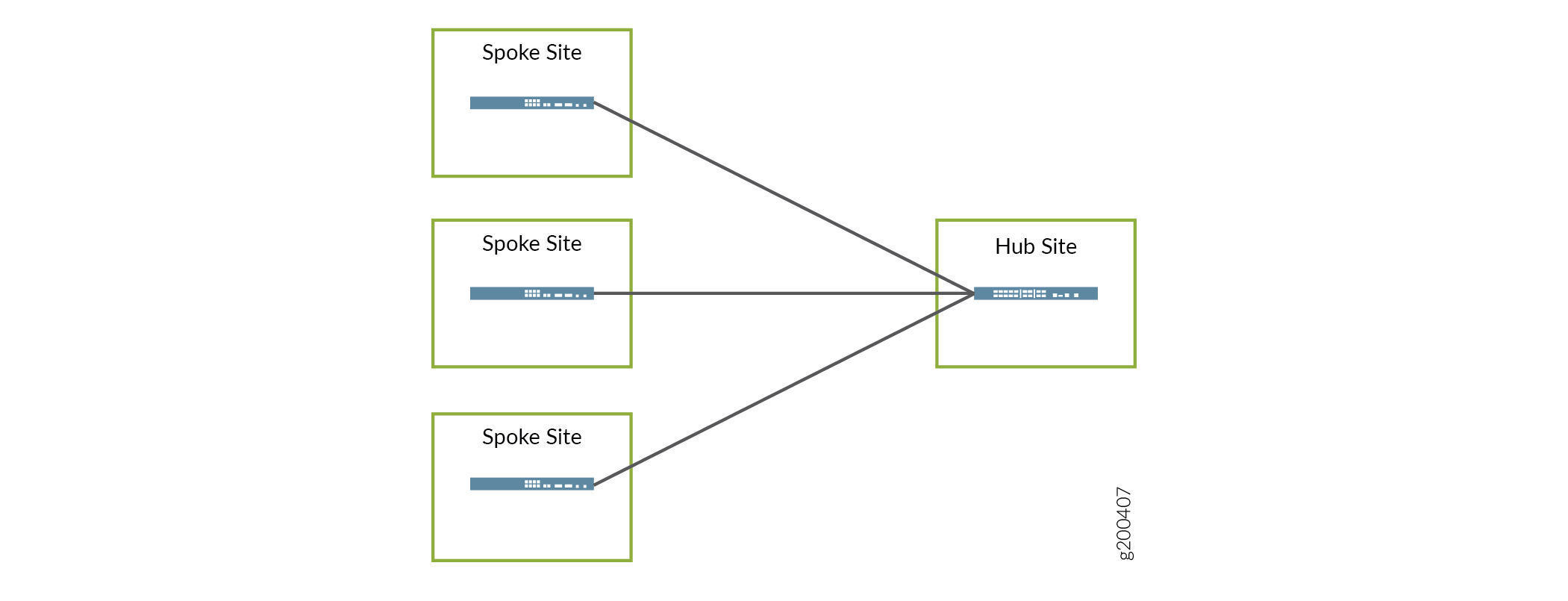
Full Mesh Topology– This topology is also available for SD-WAN deployments. Direct site-to-site communication is allowed and every site is considered a hub site. Figure 4 shows a very basic example of a full mesh topology. VNFs can be deployed at any of the locations shown. This topology requires more overlay networks than the hub-and-spoke topology so consideration must be given where resources are constrained.
Figure 4: Full Mesh Topology 
Points of Presence (POPs)
A POP is a place, usually at the SP Cloud edge, where network services can be deployed and underlay network connections are made to remote sites. POPs can have PE router, IPSec concentrator, and SDN Gateway devices assigned to them.
POPs are used in distributed CPE and SD-WAN deployments as a way to locate network access and network services closer to the users who need them. Different network services and different connection types can be offered at each POP, depending on need and availability. POPs can be named in whatever way makes the most sense to the SP.
Sites
Sites are the branch offices or remote locations from which customers access the network services provided by the CSO solutions. A site is assigned to a POP and the type of sites available for creation depend on the type of deployment you are creating: Centralized CPE, Distributed CPE, or SD-WAN. Sites can be created by the Global administrator, the OpCo administrator, or the Tenant administrator. Sites can be named whatever makes sense for the SP or Tenant. Table 1 lists what types of sites can be created within each deployment.
Table 1: Site types by Deployment
Deployment | Available Site Types | Uses | Service Notes |
|---|---|---|---|
Centralized CPE | Local Service Edge | The local service edge is the automation point in the network closest to the customer location (SDN gateway) where centralized service VNFs can be attached. Use this site type for customers who access the Internet through a VPN in the SP cloud. | Site acts as a service attachment point. During site creation, an optional VRF can be created on the gateway router to handle routing and forwarding specifically for the centralized service attachment point. If a PNE is configured, then it must be associated with a site and a VNF must be created on the PNE for each associated site. |
Regional Service Edge | Automation point deeper in the service provider network that performs centralized services for many branches, for example: a hub router deep inside the enterprise network. Use this site type for each branch location in the customer network. For use with customers who access the Internet from their local site. | The end-point is identified only by route-target. The centralized VNF (network-service) connectivity is orchestrated only by peering using BGP routing protocols. No configuration changes are made to the hub router. | |
Hybrid WAN/Distributed CPE | Local Service Edge | Automation point in the network closest to the customer CPE location, for example: the PE-Router, where centralized service VNFs can be attached. Use this site type for customers who access the Internet through a VPN in the SP cloud. | The Local Service Edge site acts as a service attachment point. During site creation, an optional VRF can be created on the gateway router to handle routing and forwarding specifically for the centralized service attachment point. |
Regional Service Edge | Automation point deeper in the service provider network that performs centralized services for many branches, for example: a hub router deep inside the enterprise network. Use this site type for each branch location in the customer network. For use with customers who access the Internet from their local site. | The end-point is identified only by route-target. The centralized VNF (network-service) connectivity is orchestrated only by peering using BGP routing protocols. No configuration changes are made to the hub router. | |
SD-WAN | |||
On-premise Spoke | Use this site type for locating NFX Series or SRX Series devices at customer sites in either a hub-and-spoke or full mesh topology. | SRX Series devices deployed as on-premises spoke devices can not host VNF-based network services. NFX devices used as on-premise spoke devices can support ADSL, VDSL, and LTE access links, but cannot be used for ZTP. The DSL access links allow configuration of PPPoE. Starting with CSO Release 4.0, LTE access links can be used as primary DATA, OAM, or DATA_OAM links. Local breakout is supported on this type of site when using the full mesh topology. | |
Cloud Hub | Use this type of site for locating MX Series or SRX series in a SP cloud. The cloud hub devices are used for establishment of IPSec tunnels. Cloud hub devices are multi-tenant (shared amongst multiple sites) through the use of VRF instances configured on them. | You must specify the capability of the cloud hub devices when setting up the site. Specifying OAM capabilities allows the hub to help create secure OAM networks with the CPE devices. A cloud hub device is required for the full mesh topology. Local breakout is not supported on Cloud Hub sites. | |
Cloud Spoke | This type of site is specifically for deploying a vSRX in a tenant’s Amazon Web Services (AWS) Virtual Private Cloud (VPC) | Firewall and UTM services are available to protect the customer’s resources in AWS VPC. Connectivity between VPC resources and on-premise sites. WAN_0, WAN_1, and LAN interfaces need to be predefined in VPC. Two elastic IP addresses need to be reserved in VPC to attach to WAN interfaces later. VPC should be created and attached to an Internet gateway. Only hub-and-spoke topology supported. Hub needs to have public IPs on in its WAN interfaces. Hub WAN interface type should be set as Internet during onboarding. |
Customer Premises Equipment (CPE)
CPE devices are those devices that are placed at remote locations in the site types mentioned previously. CPE devices serve their functions in Hybrid WAN deployments or as on-premises spoke devices in SD-WAN deployments.
NFX250 and NFX150 Series Network Services Platforms, SRX300 Series Services Gateways, and vSRX can all be deployed as CPE devices. The NFX series devices provide the ability to host VNFs that can be deployed within the Hybrid WAN and SD-WAN solutions. The SRX Series devices cannot host VNFs but can provide their built-in security functions of firewall, UTM, and NAT as protection for the customer sites. In these cases, VNFs can still be deployed behind the SRX, but those VNFs cannot be managed by CSO.
Virtual Route Reflector (VRR)
The VRR is part of CSO's SD-WAN controller. It is one of the virtual machines that get provisioned and installed during the installation process. To facilitate the routing needed in the SD-WAN deployment , the VRR forms BGP sessions with CPE spokes and hub devices using the underlay interface designated as OAM or OAM_AND_DATA during the configure site GUI workflow for site onboarding. Starting in CSO Release 4.0.0, the OAM interfaces can be implemented using dedicated IPSec tunnels which allows CPE and hub devices to be behind NAT.
Service-Level Agreement (SLA) Profiles and Policies
CSO allows for the creation of SLA profiles that can be mapped to SD-WAN policies for traffic management in an SD-WAN deployment. SLA profiles are created for applications or groups of applications for all tenants. An SLA profile consists of a set of configurable constraints that can be defined in the unified portal for both the Administration and Customer Portals.
You can set path preference for each of the connection paths from site-to-site or from site-to-hub, set SLA parameters for throughput, packet lost, latency, and jitter, set class of service for various types of traffic, and set rate limiters to control upstream and downstream rates and burst sizes.
When creating an SLA profile, you must set either path preference or one of the SLA parameters. Both fields cannot be left blank at the same time.
See Configuring Application SLA Profiles in the Contrail Service Orchestration User Guide for more details.
Firewall Policies
Accessed through the Customer Portal, CSO presents firewall policies as intent-based policies. Firewall policies provide security functionality by enforcing intents on traffic that passes through a device. Traffic is permitted or denied based on the action defined as the firewall policy intent. If your intention is to block HTTP-based traffic from social media sites, but allow HTTP-based traffic from Microsoft Outlook, you can create an intent policy to do that.
See Firewall Policy Overview for more information.

