例:PTXルーターでのローカルポートミラーリングの設定
この例では、Junos Evolvedを実行しているPTXプラットフォームでローカルポートミラーリングを構成および検証する方法を示します。PTXプラットフォームには、PTX10004、PTX10008、PTX10016シャーシのPTX10001-36MR、LC1201、LCPTX10016が含まれます
始める前に
| ハードウェアとソフトウェアの要件 | Junos OS Evolvedリリース22.2R1.12-EVO以降。 PTX10001-36MR サポートされているプラットフォームとJunos OSバージョンの全リストについては、機能エクスプローラーを参照してください。 |
| 推定読書時間 |
15分。 |
| 推定設定時間 |
30分 |
| ビジネスへの影響 |
この設定例を使用して、ローカルポートミラーリング機能を設定します。ポートミラーは、デバッグやセキュリティ関連のタスクに重要なツールです。ミラートラフィックは、さまざまなツールによってオフラインで分析し、プロトコルの相互作用を確認したり、異常検知を行うことができます。 |
| 詳細はこちら |
ポートミラーリングについて理解するには、ポートミラーリングとアナライザーを参照してください |
| 詳細情報 |
ラーニングポータル |
機能の概要
表1は 、この例で導入されたプロトコルと技術の概要を示しています。
| ルーティングおよびシグナリングプロトコル |
|
| OSPFおよびOSPF3 |
すべてのルーターは、OSPF と OSPF3 を IGP として実行します。すべてのルーターは、エリア0(バックボーンエリアとも呼ばれます)に属しています。OSPF/OSPF3ルーティングドメインは、トポロジー内のすべてのネットワークとインターフェイスへの内部到達性を提供します。 この例では、CEデバイスとPE/Pデバイスは同じIGPルーティングドメインの一部です。その結果、コアを介して CE トラフィックを転送するための PE デバイス間のトンネルは必要ありません。さらに、これはローカルミラーのユースケースであるため、ミラーリングされたトラフィックを監視ステーションに送信する場合にGREカプセル化は必要ありません。 |
| ルーティングプロトコル |
|
| IPv4 および IPv6 |
すべてのデバイスは、IPv4 と IPv6 の両方のルーティングをサポートするように構成されています。 |
| アナライザ(監視ステーション) |
|
| CentosとWireshark |
アナライザは、WiresharkのGUIバージョンでCentos 7.xを実行します。 |
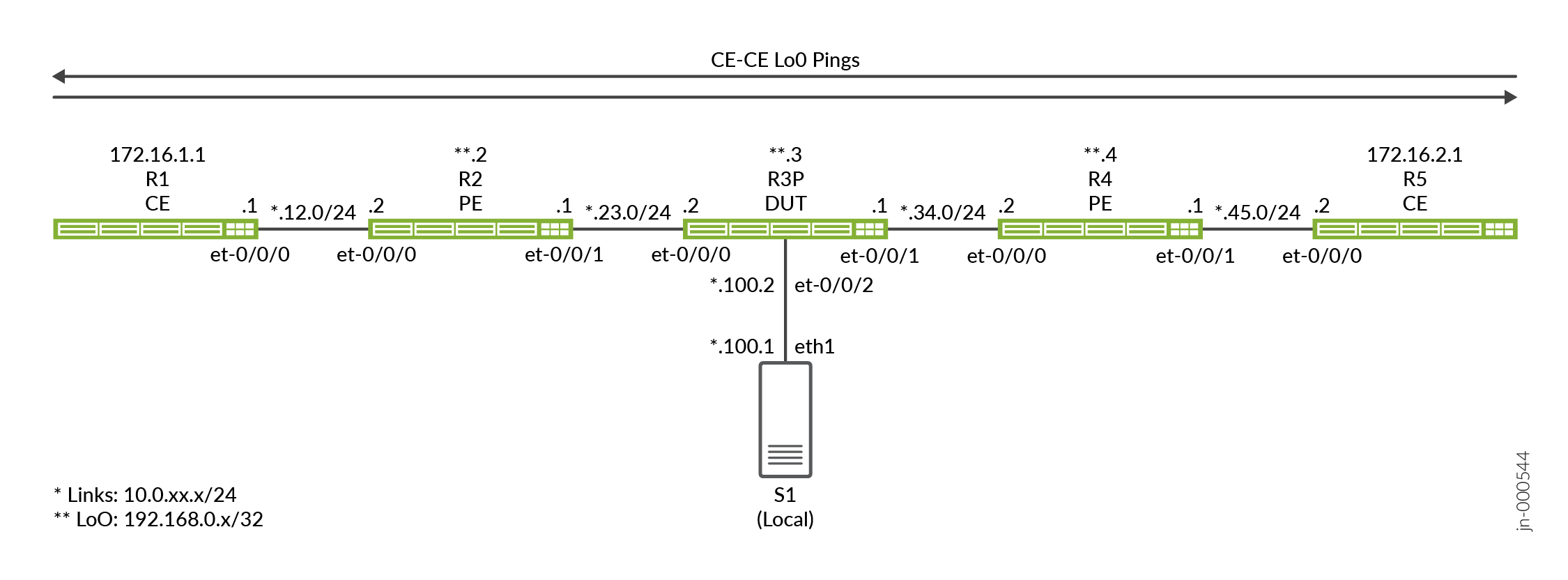
トポロジーの概要
この例では、R3デバイスがDUT(テスト対象デバイス)として機能しており、ここでポートミラーリングが設定されています。デバイスは、ファイアウォールフィルターを使用して、CEデバイスに関連付けられたIPアドレスを照合し、ポートミラーアクションをトリガーします。イングレスフィルターとエグレスフィルターの組み合わせを使用して、CEデバイス(R1およびR5)間を流れるリクエストトラフィックとレスポンストラフィックの両方をミラーリングします。
パケットサンプリングを呼び出すファイアウォールフィルターは、R3デバイス上の1つ以上のトランジットインターフェイスに適用されます。
| デバイス名 | 役割 |
機能 |
| CE | サンプリングが正しく動作することを確認するためにテストトラフィックを送信するCEデバイス。 | これらのデバイスは CE デバイスとして指定されます。ほとんどの場合、CEデバイスはVPNサービスの一部です。ここでは、メインインスタンスのIP接続を提供するために、CEにプロバイダデバイスと同じOSPFエリア0を共有しさせます。 |
| PE | CEに接続するプロバイダエッジ(PE)デバイス。 | プロバイダネットワークのエッジにあるデバイス。当社のPEは、OSPFのみを実行します。BGPとVPNは導入されていません。 |
| P | プロバイダ(P)コアルーター。 | P ルーターでポート ミラーリングのデモを行うことにしました。必要に応じて、任意のプロバイダーデバイスでポートミラーリングを設定できます。 |
| アナライザ | アナライザデバイスは、保存と分析のためにミラートラフィックを受信しました。 | アナライザの詳細については、このドキュメントの範囲外です。利用可能なオープンソースおよび商用オプションが多数あります。私たちのアナライザは、WiresharkのGUIOバージョンをサポートするGnomeデスクトップでCentos 7.xを実行しています。 |
トポロジー図
R3 の設定手順
CLIのナビゲーションについては、設定モードでのCLIエディターの使用を参照してください
すべてのデバイスで完全な設定を行うには、次を参照してください。 付録2:すべてのデバイスでコマンドを設定する
このセクションでは、DUT(この例ではPデバイス(R3)を構成するために必要な主な構成タスクに焦点を当てます。サンプリングに使用した詳細を除き、すべてのデバイスは、メインインスタンスのIPv6およびIPv4接続をサポートする同様のベースライン設定になっています。
-
IPv4およびIPv6ルーティングのベースラインを設定します。これには、IPv4 と IPv6 の両方のループバック インターフェイスとコア インターフェイスの番号付けが含まれます。また、OSPFおよびOSPFv3ルーティングプロトコルを定義して、すべてのネットワークインターフェイス間の到達性を提供します。
パッシブIGPインスタンスは、アナライザに接続されたインターフェイスにプロビジョニングされます。これにより、インターフェイス上で hello パケットを生成することなく、診断目的で到達可能性が得られます。OSPF隣接関係は、アナライザデバイスに対して予期されず、必要ありません
[edit]
set interfaces et-0/0/0 unit 0 family inet address 10.0.23.2/24
set interfaces et-0/0/0 unit 0 family inet6 address 2001:db8:10:0:23::2/64
set interfaces et-0/0/1 unit 0 family inet address 10.0.34.1/24
set interfaces et-0/0/1 unit 0 family inet6 address 2001:db8:10:0:34::1/64
set interfaces et-0/0/2 unit 0 family inet address 10.0.100.2/24
set interfaces et-0/0/2 unit 0 family inet6 address 2001:db8:10:0:100::2/64
set interfaces lo0 unit 0 family inet address 192.168.0.3/32
set interfaces lo0 unit 0 family inet6 address 2001:db8:192:168:0::3/128

set routing-options router-id 192.168.0.3
set protocols ospf area 0.0.0.0 interface all
set protocols ospf area 0.0.0.0 interface fxp0.0 disable
set protocols ospf area 0 interface et-0/0/2.0 passive

set protocols ospf3 area 0.0.0.0 interface all
set protocols ospf3 area 0.0.0.0 interface fxp0.0 disable
set protocols ospf3 area 0 interface et-0/0/2.0 passive
注:ローカルミラーのユースケースで必要なのは、アナライザとポートミラーリングを実行するデバイス間のみです。この例では、アナライザに接続されたインターフェイスでパッシブ IGP を実行します。また、アナライザ上でデフォルトルートを設定して、アナライザと他のデバイス間のIP接続を提供します。これにより、アナライザと他のすべてのデバイス間の接続をテストする機能が提供されます。トポロジーで。この機能は、サンプリングデバイスとアナライザの間にレイヤー3到達性が必要なリモートポートミラーケースで最も役立ちます。
- サンプリングレートを設定します。レート 1 を使用して、一致するすべてのパケットを選択してサンプリングします。一致するすべてのトラフィックがすでにサンプリングされているため、デフォルトの
run-length0 はそのまま残されます。ミラーリングされたトラフィックの送信先となるエグレス インターフェイスとネクスト ホップ アドレスも指定する必要があります。このローカルポートミラーの例では、指定されたインターフェイスとネクストホップアドレスがDUTに直接接続されていることに注意してください。その結果、ミラーリングされたトラフィックをアナライザに送信する際にトンネルは必要ありません。また使用される必要もありません。[edit] set forwarding-options port-mirroring input rate 1 set forwarding-options port-mirroring family inet output interface et-0/0/2.0 next-hop 10.0.100.1 set forwarding-options port-mirroring family inet6 output interface et-0/0/2.0 next-hop 2001:db8:10:0:100::1
注:この設定では、アナライザがMACアドレス解決のためにDUTから送信されたARPおよびNDリクエストに応答することを前提としています。そうでない場合、またはARPトラフィックをパケットキャプチャの一部に含めないようにする場合は、静的ARPエントリを設定する必要があります。DUTに接続したアナライザデバイスのインターフェイスに正しいMACアドレスを必ず指定してください。
-
IPv4パケットで一致させてからミラーリングするファイアウォールフィルターを定義します。フィルターのアクションは、ポートミラーアクションを指定することに注意してください。このアクションにより、一致するトラフィックが、以前に設定したポートミラーリングインスタンスに誘導されます。CE1 と CE2 の送信元アドレスと宛先アドレスにそれぞれ 1 つずつ、2 つのフィルターが定義されます。フィルターには、正常動作の確認を支援するカウント機能が含まれています。
Junosファイアウォールフィルターのデフォルトの
deny-allアクションを上書きする最後のaccept-all条件を見逃さないでください。[edit] set firewall filter mirror_ce1 term term1 from source-address 172.16.1.1/32 set firewall filter mirror_ce1 term term1 from destination-address 172.16.2.1/32 set firewall filter mirror_ce1 term term1 then count mirror_ce1 set firewall filter mirror_ce1 term term1 then port-mirror set firewall filter mirror_ce1 term term1 then accept set firewall filter mirror_ce1 term accept-all then accept set firewall filter mirror_ce2 term term1 from source-address 172.16.2.1/32 set firewall filter mirror_ce2 term term1 from destination-address 172.16.1.1/32 set firewall filter mirror_ce2 term term1 then count mirror_ce2 set firewall filter mirror_ce2 term term1 then port-mirror set firewall filter mirror_ce2 term term1 then accept set firewall filter mirror_ce2 term accept-all then accept
-
IPv6パケットを照合してミラーリングするファイアウォールフィルターを定義します。
[edit]
set firewall family inet6 filter ce1_v6 term 1 from source-address 2001:db8:172:16:1::1/128
set firewall family inet6 filter ce1_v6 term 1 from destination-address 2001:db8:172:16:2::1/128
set firewall family inet6 filter ce1_v6 term 1 then count ce1_v6
set firewall family inet6 filter ce1_v6 term 1 then port-mirror
set firewall family inet6 filter ce1_v6 term 1 then accept
set firewall family inet6 filter ce1_v6 term accept-all then accept
set firewall family inet6 filter ce2_v6 term 1 from source-address 2001:db8:172:16:2::1/128
set firewall family inet6 filter ce2_v6 term 1 from destination-address 2001:db8:172:16:1::1/128
set firewall family inet6 filter ce2_v6 term 1 then count ce2_v6
set firewall family inet6 filter ce2_v6 term 1 then port-mirror
set firewall family inet6 filter ce2_v6 term 1 then accept
set firewall family inet6 filter ce2_v6 term accept-all then accept
-
IPv4 および IPv6 フィルターを目的のインターフェイスに適用します。この例では、両方のフィルターをet-0/0/0インターフェイスに適用します。フィルター適用の方向性に注意してください。各 CE トラフィック フロー(IPv4 または IPv6)に対して、一方のフィルターをイングレスとして適用し、もう一方のフィルターをエグレスとして適用します。この適用方法は、アドレス割り当てとトラフィックの方向性を考慮したフィルターの記述方法と互換性があります。
[edit]
set interfaces et-0/0/0 unit 0 family inet filter input mirror_ce1
set interfaces et-0/0/0 unit 0 family inet filter output mirror_ce2

set interfaces et-0/0/0 unit 0 family inet6 filter input ce1_v6
set interfaces et-0/0/0 unit 0 family inet6 filter output ce2_v6
検証
-
OSPFおよびOSPF3ネイバーとすべてのループバックアドレスへのルートを確認します。
user@r3-ptx> show ospf neighbor

Address          Interface              State           ID               Pri  Dead
10.0.23.1        et-0/0/0.0             Full            192.168.0.2      128    31
10.0.34.2        et-0/0/1.0             Full            192.168.0.4      128    38

user@r3-ptx> show ospf3 neighbor

ID               Interface              State     Pri   Dead
192.168.0.2      et-0/0/0.0             Full      128     30
  Neighbor-address fe80::c6ba:25ff:fe48:9
192.168.0.4      et-0/0/1.0             Full      128     32
  Neighbor-address fe80::6204:30ff:fe6e:ffff

regress@r3-ptx> show route protocol ospf | match /32
172.16.1.1/32      *[OSPF/10] 01:04:02, metric 2
172.16.2.1/32      *[OSPF/10] 6d 00:47:07, metric 2
192.168.0.2/32     *[OSPF/10] 01:04:02, metric 1
192.168.0.4/32     *[OSPF/10] 6d 00:47:12, metric 1
224.0.0.5/32       *[OSPF/10] 6d 00:48:28, metric 1
224.0.0.6/32       *[OSPF/10] 6d 00:48:28, metric 1

regress@r3-ptx> show route protocol ospf3 | match /128
2001:db8:172:16:1::1/128
2001:db8:172:16:2::1/128
2001:db8:192:168::2/128*[OSPF3/10] 01:04:09, metric 1
2001:db8:192:168::4/128*[OSPF3/10] 6d 00:47:15, metric 1
ff02::5/128        *[OSPF3/10] 6d 00:48:35, metric 1
ff02::6/128        *[OSPF3/10] 6d 00:48:35, metric 1
-
R3 のポートミラーリングインスタンスを確認します。ポートミラーリング状態がミラーリングインターフェイスに対して
upされていることを確認します。IPv4 と IPv6 の両方のファミリのup状態を必ず確認してください。ここで、DUTとアナライザ間のIP接続を確認することをお勧めします。この設定では、ネットワークのすべてのポイントからの ping テストを許可するように、アナライザにデフォルト ルートが設定されています。技術的には、これはローカルポートミラーリングの例であるため、アナライザに到達できるのはDUT(R3)だけです。user@r3-ptx> show forwarding-options port-mirroring Instance Name: &global_instance Instance Id: 1 Input parameters: Rate : 1 Run-length : 0 Maximum-packet-length : 0 Output parameters: Family State Destination Next-hop inet up et-0/0/2.0 10.0.100.1 inet6 up et-0/0/2.0 2001:db8:10:0:100::1 -
R3 のファイアウォール カウンターとインターフェイス統計をクリアします。次に、CEデバイス間でIPv4およびIPv6テストトラフィックを生成し、R3にファイアウォールカウンターを表示します。R3に適用されたフィルターがテストトラフィックを正しく反映していることを確認します。
user@r3-ptx> clear firewall all
user@r3-ptx> clear interfaces statistics all
user@r1-ptx> ping 172.16.2.1 source 172.16.1.1 count 10 rapid
PING 172.16.2.1 (172.16.2.1) from 172.16.1.1 : 56(84) bytes of data.
--- 172.16.2.1 ping statistics ---
10 packets transmitted, 10 received, 0% packet loss, time 711ms
rtt min/avg/max/mdev = 11.161/72.078/364.497/121.714 ms, ipg/ewma 78.945/100.962 ms

user@r1-ptx> ping 2001:db8:172:16:2::1 source 2001:db8:172:16:1::1 count 10 rapid
 ping 2001:db8:172:16:2::1 source 2001:db8:172:16:1::1 count 10 rapid
PING 2001:db8:172:16:2::1(2001:db8:172:16:2::1) from 2001:db8:172:16:1::1 : 56 data bytes

--- 2001:db8:172:16:2::1 ping statistics ---
10 packets transmitted, 10 received, 0% packet loss, time 2436ms
rtt min/avg/max/mdev = 11.363/247.188/518.314/226.132 ms, pipe 2, ipg/ewma 270.652/201.439 ms
-
R3 のファイアウォール カウンターを表示します。R3に適用されたフィルターが、生成したテストトラフィックを正しく反映しているかどうかを確認します。
user@r3-ptx> show firewall
Filter: mirror_ce1
Counters:
Name                                                Bytes              Packets
mirror_ce1                                             840                   10

Filter: mirror_ce2
Counters:
Name                                                Bytes              Packets
mirror_ce2                                             840                   10

Filter: ce1_v6
Counters:
Name                                                Bytes              Packets
ce1_v6                                                1040                   10

Filter: ce2_v6
Counters:
Name                                                Bytes              Packets
ce2_v6                                                1040                   10
-
アナライザに接続されたR3のet-0/0/2.0インターフェイスのインターフェイス統計情報を表示します。目的は、生成されたテストトラフィックに関連する出力トラフィックカウンターを確認することです。IPv4 と IPv6 の両方で 10 回の ping があり、リクエストと応答の両方をミラーリングすると、約 40 個の出力パケットが表示されることが予想されます。
user@r3-ptx> show interfaces et-0/0/2.0 detail Logical interface et-0/0/2.0 (Index 1017) (SNMP ifIndex 541) (Generation 704374637676) Flags: Up SNMP-Traps Encapsulation: ENET2 Traffic statistics: Input bytes : 0 Output bytes : 3760 Input packets: 0 Output packets: 40 Local statistics: Input bytes : 0 Output bytes : 0 Input packets: 0 Output packets: 0 Transit statistics: Input bytes : 0 0 bps Output bytes : 3760 0 bps Input packets: 0 0 pps Output packets: 40 0 pps -
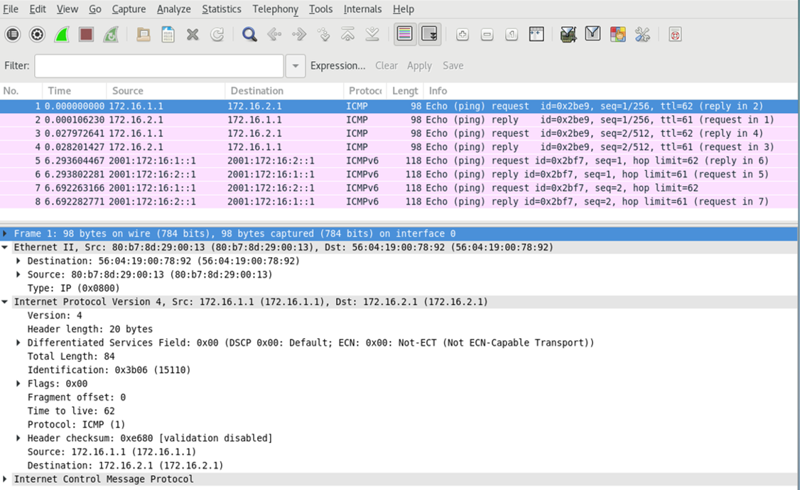
監視ステーションで tcpdump または選択した分析アプリケーションを実行して、ミラーリングされたテスト・トラフィックの受信と処理を確認します。キャプチャのサイズを小さくするために、IPv4とIPv6それぞれに対して2つのping要求のみで新しいテストトラフィックを生成しました。キャプチャとデコードは、ファイアウォールフィルターのマッチングに基づいて、IPv4とIPv6のポートミラーリングが期待どおりに機能していることを確認します。要求トラフィックと応答トラフィックの両方が表示されていることに注意してください。
また、キャプチャでは、レイヤー3トラフィックのみがミラーリングされることに注意してください。ここに示されているレイヤー2カプセル化は、ミラーリングされたトラフィックをアナライザに転送するときにDUT(R3)によって生成されます。元のレイヤー 2 フレームを保持する必要がある場合、イーサネット スイッチングや VXLAN などのレイヤー 2 サービスにポート ミラーリングを設定できます。
付録:すべてのデバイスでコマンドを設定する
この例をすばやく設定するには、以下のコマンドをコピーしてテキストファイルに貼り付け、改行を削除して、ネットワーク構成に合わせて必要な詳細を変更し、[edit]階層レベルのCLIにコマンドをコピー&ペーストします。
R1(CE)
set system host-name r1-ptx
set interfaces et-0/0/0 unit 0 family inet address 10.0.12.1/24
set interfaces et-0/0/0 unit 0 family inet6 address 2001:db8:10:0:12::1/64
set interfaces lo0 unit 0 family inet address 172.16.1.1/32
set interfaces lo0 unit 0 family inet6 address 2001:db8:172:16:1::1/128
set routing-options router-id 172.16.1.1
set protocols ospf area 0.0.0.0 interface all
set protocols ospf area 0.0.0.0 interface fxp0.0 disable
set protocols ospf3 area 0.0.0.0 interface all
set protocols ospf3 area 0.0.0.0 interface fxp0.0 disable
R2(PE)
set system host-name r2-ptx
set interfaces et-0/0/0 unit 0 family inet address 10.0.12.2/24
set interfaces et-0/0/0 unit 0 family inet6 address 2001:db8:10:0:12::2/64
set interfaces et-0/0/1 unit 0 family inet address 10.0.23.1/24
set interfaces et-0/0/1 unit 0 family inet6 address 2001:db8:10:0:23::1/64
set interfaces et-0/0/2 unit 0 family inet tunnel-termination
set interfaces et-0/0/2 unit 0 family inet address 10.0.100.2/24
set interfaces lo0 unit 0 family inet address 192.168.0.2/32
set interfaces lo0 unit 0 family inet6 address 2001:db8:192:168:0::2/128
set routing-options router-id 192.168.0.2
set protocols ospf area 0.0.0.0 interface all
set protocols ospf area 0.0.0.0 interface fxp0.0 disable
set protocols ospf3 area 0.0.0.0 interface all
set protocols ospf3 area 0.0.0.0 interface fxp0.0 disable
R3(DUT)
set system host-name r3-ptx
set interfaces et-0/0/0 unit 0 family inet filter input mirror_ce1
set interfaces et-0/0/0 unit 0 family inet filter output mirror_ce2
set interfaces et-0/0/0 unit 0 family inet address 10.0.23.2/24
set interfaces et-0/0/0 unit 0 family inet6 filter input ce1_v6
set interfaces et-0/0/0 unit 0 family inet6 filter output ce2_v6
set interfaces et-0/0/0 unit 0 family inet6 address 2001:db8:10:0:23::2/64
set interfaces et-0/0/1 unit 0 family inet address 10.0.34.1/24
set interfaces et-0/0/1 unit 0 family inet6 address 2001:db8:10:0:34::1/64
set interfaces et-0/0/2 unit 0 family inet address 10.0.100.2/24
set interfaces et-0/0/2 unit 0 family inet6 address 2001:db8:10:0:100::2/64
set interfaces lo0 unit 0 family inet address 192.168.0.3/32
set interfaces lo0 unit 0 family inet6 address 2001:db8:192:168:0::3/128
set forwarding-options port-mirroring input rate 1
set forwarding-options port-mirroring input run-length 0
set forwarding-options port-mirroring family inet output interface et-0/0/2.0 next-hop 10.0.100.1
set forwarding-options port-mirroring family inet6 output interface et-0/0/2.0 next-hop 2001:db8:10:0:100::1
set firewall family inet6 filter ce1_v6 term 1 from source-address 2001:db8:172:16:1::1/128
set firewall family inet6 filter ce1_v6 term 1 from destination-address 2001:db8:172:16:2::1/128
set firewall family inet6 filter ce1_v6 term 1 then count ce1_v6
set firewall family inet6 filter ce1_v6 term 1 then port-mirror
set firewall family inet6 filter ce1_v6 term 1 then accept
set firewall family inet6 filter ce1_v6 term accept-all then accept
set firewall family inet6 filter ce2_v6 term 1 from source-address 2001:db8:172:16:2::1/128
set firewall family inet6 filter ce2_v6 term 1 from destination-address 2001:db8:172:16:1::1/128
set firewall family inet6 filter ce2_v6 term 1 then count ce2_v6
set firewall family inet6 filter ce2_v6 term 1 then port-mirror
set firewall family inet6 filter ce2_v6 term 1 then accept
set firewall family inet6 filter ce2_v6 term accept-all then accept
set firewall filter mirror_ce1 term 1 from source-address 172.16.1.1/32
set firewall filter mirror_ce1 term 1 from destination-address 172.16.2.1/32
set firewall filter mirror_ce1 term 1 then count mirror_ce1
set firewall filter mirror_ce1 term 1 then port-mirror
set firewall filter mirror_ce1 term 1 then accept
set firewall filter mirror_ce1 term accept-all then accept
set firewall filter mirror_ce2 term term1 from source-address 172.16.2.1/32
set firewall filter mirror_ce2 term 1 from destination-address 172.16.1.1/32
set firewall filter mirror_ce2 term 1 then count mirror_ce2
set firewall filter mirror_ce2 term 1 then port-mirror
set firewall filter mirror_ce2 term 1 then accept
set firewall filter mirror_ce2 term accept-all  then accept
set routing-options router-id 192.168.0.3
set protocols ospf area 0.0.0.0 interface all
set protocols ospf area 0.0.0.0 interface fxp0.0 disable
set protocols ospf area 0.0.0.0 interface et-0/0/2.0 passive
set protocols ospf3 area 0.0.0.0 interface all
set protocols ospf3 area 0.0.0.0 interface fxp0.0 disable
set protocols ospf3 area 0.0.0.0 interface et-0/0/2.0 passive
R4(PE)
set system host-name r4-ptx
set interfaces et-0/0/0 unit 0 family inet address 10.0.34.2/24
set interfaces et-0/0/0 unit 0 family inet6 address 2001:db8:10:0:34::2/64
set interfaces et-0/0/1 unit 0 family inet address 10.0.45.1/24
set interfaces et-0/0/1 unit 0 family inet6 address 2001:db8:10:0:45::1/64
set interfaces et-0/0/2 unit 0 family inet address 10.0.200.2/24
set interfaces et-0/0/2 unit 0 family inet6 address 2001:db8:10:0:200::2/64
set interfaces lo0 unit 0 family inet address 192.168.0.4/32
set interfaces lo0 unit 0 family inet6 address 2001:db8:192:168:0::4/128
set routing-options router-id 192.168.0.4
set protocols ospf area 0.0.0.0 interface all
set protocols ospf area 0.0.0.0 interface fxp0.0 disable
set protocols ospf3 area 0.0.0.0 interface all
set protocols ospf3 area 0.0.0.0 interface fxp0.0 disable
R5(CE)
set system host-name r5-ptx
set interfaces et-0/0/0 unit 0 family inet address 10.0.45.2/24
set interfaces et-0/0/0 unit 0 family inet6 address 2001:db8:10:0:45::2/64
set interfaces lo0 unit 0 family inet address 172.16.2.1/32
set interfaces lo0 unit 0 family inet6 address 2001:db8:172:16:2::1/128
set routing-options router-id 172.16.2.1
set protocols ospf area 0.0.0.0 interface all
set protocols ospf area 0.0.0.0 interface fxp0.0 disable
set protocols ospf3 area 0.0.0.0 interface all
set protocols ospf3 area 0.0.0.0 interface fxp0.0 disable