이 페이지의 내용
AWS 구축의 멀티노드 고가용성
Amazon Web Services(AWS) 구축에서 vSRX 가상 방화벽 인스턴스에 대한 멀티노드 고가용성 지원을 이해하려면 이 주제를 읽어보십시오.
AWS의 멀티노드 고가용성
AWS에 구축된 vSRX 가상 방화벽 방화벽에서 멀티노드 고가용성을 구성할 수 있습니다. 참여 노드는 활성 컨트롤 플레인과 데이터 플레인을 동시에 실행하고 노드는 서로 백업하여 시스템 또는 하드웨어 실패 시 빠른 동기화된 페일오버를 보장합니다. 두 디바이스 간의 섀시 간 링크(ICL) 연결은 상태 정보를 동기화 및 유지하고 디바이스 장애 조치 시나리오를 처리합니다.
먼저 AWS 구축과 관련된 멀티노드 고가용성 용어에 대해 알아보겠습니다.
용어
| 용어 | 설명 |
|---|---|
| 탄력적 IP 주소 |
지정된 네트워크 또는 인터넷에서 라우팅할 수 있는 공용 IPv4 주소입니다. 탄력적 IP 주소는 멀티노드 고가용성 설정에서 모든 노드의 인터페이스에 동적으로 바인딩됩니다. 언제든지 이러한 주소는 하나의 인터페이스에만 바인딩되며 동일한 노드에도 바인딩됩니다. 멀티노드 고가용성 설정은 탄력적 IP 주소를 사용하여 AWS 배포의 트래픽을 제어합니다. 탄력적 IP 주소는 레이어 3 구축의 유동 IP 주소 또는 기본 게이트웨이 구축의 가상 IP 주소와 유사하게 작동합니다. 활성 SRG1이 있는 노드는 탄력적 IP 주소를 소유하고 트래픽을 끌어옵니다. |
| 섀시 간 링크(ICL) |
멀티노드 고가용성 시스템에서 라우팅된 네트워크를 통해 노드를 연결하는 IP 기반 링크(논리적 링크). 보안 디바이스는 ICL을 사용하여 상태 정보를 동기화 및 유지 관리하고 디바이스 장애 조치 시나리오를 처리합니다. ge-0/0/0 인터페이스만 사용하여 ICL을 구성할 수 있습니다. ICL은 AWS에서 할당한 MAC 주소(vSRX 가상 방화벽에서 생성된 가상 MAC가 아님)를 사용합니다. ICL을 구성할 때 IP 주소가 가상 프라이빗 클라우드(VPC)의 서브넷인지 확인하십시오. Multibode 고가용성은 VPC 간 배치를 지원하지 않습니다 |
| 주니퍼 서비스 이중화 프로토콜(jsrpd) 프로세스 | 활성 상태 확인 및 실행을 관리하고 분할 두뇌 보호를 제공하는 프로세스입니다. |
IPsec VPN 지원
Junos OS 릴리스 24.4R1부터 AWS 구축에서 액티브/백업 멀티노드 고가용성을 위한 IPsec VPN을 지원합니다.
제한 사항
멀티노드 고가용성은 퍼블릭 클라우드 구축에서 여러 SRG 구성(액티브/액티브)을 지원하지 않습니다. 액티브/백업 모드는 SRG0 및 SRG1을 지원합니다. 스테이트풀 액티브/백업 모드에서 작동하는 SRG1에 IPsec VPN 터널 고정. 모든 VPN 터널은 SRG1이 활성화된 디바이스에서 종료됩니다.
아키텍처
그림 1은 AWS의 멀티노드 고가용성 구축에서 HA 쌍을 형성하는 두 개의 vSRX 가상 방화벽 인스턴스를 보여줍니다. 하나의 vSRX 가상 방화벽 인스턴스는 활성 노드로 작동하고 다른 인스턴스는 백업 노드로 작동합니다.
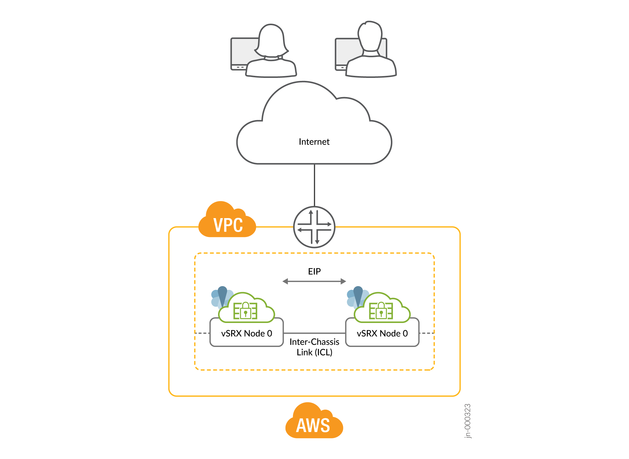
멀티노드 고가용성 설정에서 ICL은 두 노드(vSRX 가상 방화벽 인스턴스)를 연결하고 컨트롤 플레인 및 데이터 플레인 상태를 동기화하는 데 도움이 됩니다.
멀티노드 고가용성 설정에서 2개의 vSRX 가상 방화벽 인스턴스가 활성/백업 모드에서 작동합니다. 두 노드는 컨트롤 및 데이터 플레인 상태를 동기화하기 위해 ICL을 사용하여 서로 연결됩니다. SRG1이 활성화된 vSRX 가상 방화벽 인스턴스는 탄력적 IP 주소를 호스팅합니다. 활성 노드는 탄력적 IP 주소를 사용하여 트래픽을 해당 방향으로 안내합니다. 백업 노드는 대기 모드로 유지되며 페일오버 시 인계됩니다.
jsrpd(주니퍼 서비스 이중화 프로토콜) 프로세스는 AWS 인프라와 통신하여 활성화 결정 및 적용을 수행하고 스플릿 브레인 보호를 제공합니다.
장애 조치 중에 탄력적 IP 주소는 AWS SDK API를 트리거하여 이전 활성 노드에서 새 활성 노드로 이동하고 트래픽을 새 활성 노드로 끌어 옵니다. AWS는 트래픽을 새 활성 노드로 우회하기 위해 라우팅 테이블을 업데이트합니다. 이 메커니즘을 통해 클라이언트는 단일 IP 주소를 사용하여 노드와 통신할 수 있습니다. 참여 네트워크/세그먼트에 연결하는 인터페이스에서 탄력적 IP 주소를 구성합니다.
스플릿 브레인 보호
두 노드 간의 ICL이 다운되면 각 노드는 프로브를 사용하여 피어 노드의 인터페이스 IP 주소에 ping을 시작합니다. 피어 노드가 정상이면 프로브에 응답합니다. 그렇지 않으면 jsrpd 프로세스가 AWS 인프라와 통신하여 정상 노드에 대한 활성 역할을 적용합니다.
AWS에서의 유연한 ICL 인터페이스
AWS에서 ICL을 위한 모든 ge-0/0/x 인터페이스를 구성할 수 있습니다. 이는 ICL에 ge-0/0/x를 사용할 수 있는 Azure 및 GCP의 ICL 인터페이스와 유사합니다. 이전에는 AWS의 ICL 인터페이스가 수정되어 ICL에 ge-0/0/0만 사용할 수 있었습니다.
MNHA 설정에서 작동하는 vSRX 인스턴스의 경우 AWS는 특정 태그를 사용하여 HA 페어의 적절한 식별 및 관리를 보장합니다. 처음에는 두 개의 태그가 사용됩니다.
- LocalNodeID: 이 태그는 인스턴스를 HA 쌍 내의 로컬 노드로 식별합니다.
- PeerNodeID: 이 태그는 인스턴스를 피어 노드로 식별합니다.
이 두 태그 외에도 로컬 및 피어 노드 모두에 대한 인터페이스 세부 정보를 지정하여 MNHA 설정의 구성 및 관리를 향상시키기 위해 4개의 추가 태그를 도입합니다.
- LocalTrustInterface: 프라이빗 서브넷에 연결하는 로컬 vSRX 인스턴스의 인터페이스(신뢰할 수 있는 내부 통신에 자주 사용됨).
- LocalUntrustInterface: 퍼블릭 서브넷에 연결하는 로컬 vSRX 인스턴스의 인터페이스(일반적으로 신뢰할 수 없는 외부 통신에 사용됨).
- PeerTrustInterface: 프라이빗 서브넷에 연결하는 피어 vSRX 인스턴스의 인터페이스입니다.
- PeerUntrustInterface: 퍼블릭 서브넷에 연결하는 피어 vSRX 인스턴스의 인터페이스입니다.
AWS에서 루프백 인터페이스 지원
AE 인터페이스는 AWS, GCP, Azure와 같은 퍼블릭 클라우드 플랫폼과 호환되지 않으므로 루프백 인터페이스는 이중 경로 ICL 솔루션의 일부로 사용됩니다. Azure 및 GCP는 루프백 인터페이스를 지원합니다. 이제 루프백 인터페이스를 사용하여 AWS에서도 이중 경로 ICL을 구성할 수 있습니다. AWS에서는 두 개 이상의 물리적 인터페이스(예: ge-0/0/x)를 통해 루프백 통신을 설정해야 합니다.
다음 그림은 AWS에 구축된 MNHA 설정에서 vSRX 방화벽의 토폴로지를 제공합니다.

토폴로지에서 볼 수 있듯이 두 개의 vSRX 가상 방화벽 인스턴스(vSRX 가상 방화벽-1 및 vSRX 가상 방화벽-2)가 Amazon VPC에 배포됩니다. 노드는 라우팅 가능한 IP 주소(탄력적 IP 주소)를 사용하여 서로 통신합니다. 신뢰할 수 없는 쪽은 공용 네트워크에 연결하고 신뢰하는 쪽은 보호된 리소스에 연결합니다
토폴로지는 루프백 인터페이스를 사용하여 VPC 내의 두 vSRX 방화벽 간 이중 경로 섀시 간 링크(ICL)를 구현합니다. vSRX 디바이스는 이중 ICL 연결을 위해 각각 두 개의 인터페이스(ge-0/0/0 및 ge-0/0/1)를 사용합니다. 여기서 루프백 인터페이스는 ICL 통신을 위한 논리적 엔드포인트로 사용됩니다. 물리적 인터페이스(ge-0/0/0 및 ge-0/0/1)는 루프백 통신을 위한 기본 전송 경로로 작동합니다.
예: AWS 배포에서 멀티노드 고가용성 구성
이 예에서는 Amazon Virtual Private Cloud(Amazon VPC)에 있는 두 개의 vSRX 가상 방화벽 인스턴스에서 멀티노드 고가용성을 구성하는 방법을 보여줍니다.
요구 사항
이 예에서는 다음 구성 요소를 사용합니다.
-
vSRX 가상 방화벽 인스턴스 2개
-
Junos OS 릴리스 22.3R1
-
Amazon Elastic Compute Cloud(Amazon EC2), Amazon Simple Storage Service(S3) 및 Amazon Virtual Private Cloud(Amazon VPC) 객체에 액세스, 생성, 수정 및 삭제하는 데 필요한 모든 권한이 있는 Amazon Web Services(AWS) 계정 및 ID 및 액세스 관리(IAM) 역할. 자세한 내용은 vSRX용 Amazon Virtual Private Cloud 구성 단원을 참조하십시오.
-
연결된 인터넷 게이트웨이, 서브넷, 라우팅 테이블 및 보안 그룹으로 구성된 Amazon VPC입니다. 단원은 vSRX용 Amazon Virtual Private Cloud 구성을 참조하십시오.
-
Amazon VPC에서 시작 및 구성된 vSRX 가상 방화벽 인스턴스입니다. Amazon Virtual Private Cloud에서 vSRX 인스턴스 시작 단원을 참조하십시오.
토폴로지
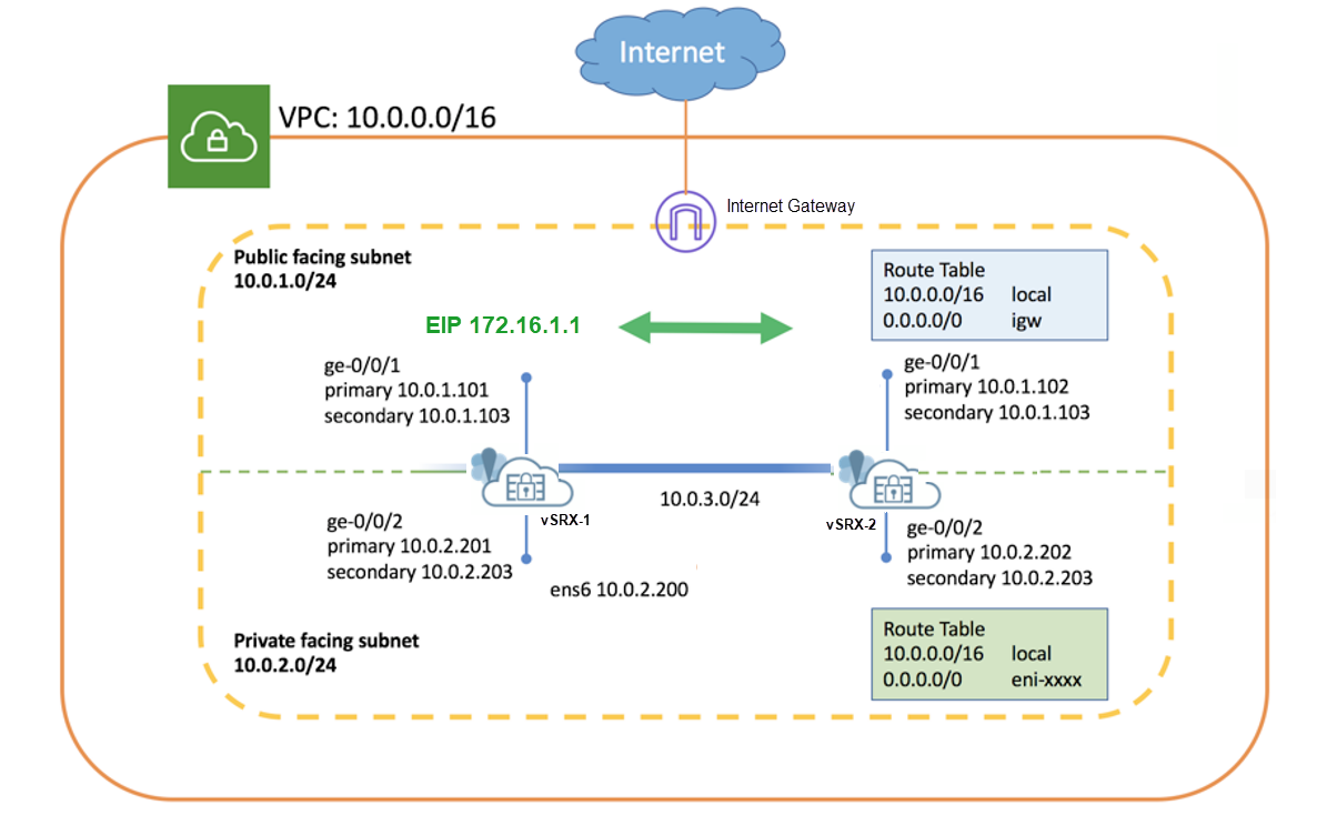
그림 3 은 이 예에서 사용되는 토폴로지를 보여줍니다.
 의 멀티노드 고가용성
토폴로지에서 볼 수 있듯이 두 개의 vSRX 가상 방화벽 인스턴스(vSRX 가상 방화벽-1 및 vSRX 가상 방화벽-2)가 Amazon VPC에 배포됩니다. 노드는 라우팅 가능한 IP 주소(탄력적 IP 주소)를 사용하여 서로 통신합니다. 신뢰할 수 없는 쪽은 공용 네트워크에 연결하고 신뢰할 수 있는 쪽은 보호된 리소스에 연결합니다.
vSRX 가상 방화벽 인스턴스에서 멀티노드 고가용성을 구성하기 전에 다음 구성을 완료합니다.
-
AWS의 인스턴스 태그를 사용하여 두 개의 vSRX 가상 방화벽 인스턴스를 멀티노드 고가용성 피어로 식별합니다. 예를 들어, vsrx-node-1 을 하나의 피어 이름(이름 옵션)으로 사용하고 vsrx-node-2 를 HA 피어(ha-peer 옵션)로 사용할 수 있습니다.
- 두 vSRX 가상 방화벽 인스턴스를 동일한 Amazon VPC 및 가용 영역에 구축합니다.
- 두 vSRX 가상 방화벽 인스턴스 모두에 IAM 역할을 할당하고 전체 권한이 있는 Amazon Elastic Compute Cloud(EC2) 인스턴스로 vSRX 가상 방화벽 인스턴스를 시작합니다.
- 퍼블릭 서브넷에 vSRX 가상 방화벽 인스턴스를 배치하여 인터넷과의 통신을 활성화합니다. Amazon VPC에서 퍼블릭 서브넷은 인터넷 게이트웨이에 액세스할 수 있습니다.
- 고가용성 쌍을 호스팅할 여러 서브넷이 있는 VPC를 구성합니다. 서브넷은 논리적 연결(물리적 케이블 연결 포트와 유사)을 사용하여 두 개의 vSRX 가상 방화벽 노드를 연결하는 데 사용됩니다. 이 예에서는 VPC에 대한 CIDR을 10.0.0.0/16으로 정의하고 총 4개의 서브넷을 생성하여 vSRX 가상 방화벽 트래픽을 호스팅했습니다. 두 vSRX 가상 방화벽 인스턴스 모두에 대해 최소 4개의 인터페이스가 필요합니다. 표 1 은 서브넷 및 인터페이스 세부 정보를 제공합니다.
표 1: 서브넷 구성 기능 포트 번호 인터페이스 연결 트래픽 유형 서브넷 관리 0 fxp0 관리 인터페이스 관리 트래픽 10.0.254.0/24 아이슬 1 ge-0/0/0 ICL에서 피어 노드로 RTO, 동기화 및 프로브 관련 트래픽 10.0.253.0/24 공개 2 ge-0/0/1 공용 네트워크에 연결합니다. (수익 인터페이스) 외부 트래픽 10.0.1.0/24 비공개 3 ge-0/0/2 프라이빗 네트워크에 연결합니다. (수익 인터페이스) 내부 트래픽 10.0.2.0/24 표에 언급된 기능과 인터페이스 매핑은 기본 구성을 위한 것입니다. 구성에서 동일한 매핑을 사용하는 것이 좋습니다.
- 기본 및 보조 IP 주소로 인터페이스를 구성합니다. 탄력적 IP 주소를 인터페이스의 보조 IP 주소로 할당할 수 있습니다. 인스턴스를 시작하는 동안 기본 IP 주소가 필요합니다. 보조 IP 주소는 페일오버 중에 하나의 vSRX 가상 방화벽 노드에서 다른 노드로 전송할 수 있습니다. 표 2 에는 이 예에서 사용된 인터페이스 및 IP 주소 매핑이 나와 있습니다.
표 2: 인터페이스 및 IP 주소 매핑 인스턴스 인터페이스 기본 IP 주소 보조 IP 주소(탄력적 IP 주소) vSRX 가상 방화벽-1 ge-0/0/1 10.0.1.101 10.0.1.103 ge-0/0/2 10.0.2.201 10.0.2.203 vSRX 가상 방화벽-2 ge-0/0/1 10.0.1.102 10.0.1.103 ge-0/0/2 10.0.2.202 10.0.2.203 -
데이터 경로에 vSRX 가상 방화벽을 포함하고 vSRX 가상 방화벽을 트래픽의 다음 홉으로 표시하도록 인접 라우터를 구성합니다. 탄력적 IP 주소를 사용하여 경로를 구성할 수 있습니다. 예를 들어 10.0.2.203 주소가 탄력적 IP 주소인 명령을 사용합니다
sudo ip route x.x.x.x/x dev ens6 via 10.0.2.203.
구성
CLI 빠른 구성
이 예를 빠르게 구성하려면, 아래 명령을 복사하여 텍스트 파일로 붙여 넣은 다음 모든 라인브레이크를 제거하고, 네트워크 구성을 일치하는 데 필요한 세부 사항을 변경하고, 계층 수준에서 [edit] 명령을 복사하여 CLI에 붙여 넣은 다음, 구성 모드에서 들어갑니다 commit .
이러한 구성은 랩 환경에서 캡처되었으며 참조용으로만 제공됩니다. 실제 구성은 환경의 특정 요구 사항에 따라 다를 수 있습니다.
vSRX 가상 방화벽-1에서
set chassis high-availability local-id 1
set chassis high-availability local-id local-ip 10.0.3.10
set chassis high-availability peer-id 2 peer-ip 10.0.3.11
set chassis high-availability peer-id 2 interface ge-0/0/0.0
set chassis high-availability peer-id 2 liveness-detection minimum-interval 400
set chassis high-availability peer-id 2 liveness-detection multiplier 5
set chassis high-availability services-redundancy-group 1 deployment-type cloud
set chassis high-availability services-redundancy-group 1 peer-id 2
set chassis high-availability services-redundancy-group 1 preemption
set chassis high-availability services-redundancy-group 1 activeness-priority 200
set security policies default-policy permit-all
set security zones security-zone fab host-inbound-traffic system-services all
set security zones security-zone fab host-inbound-traffic protocols all
set security zones security-zone fab interfaces ge-0/0/0.0
set security zones security-zone untrust host-inbound-traffic system-services all
set security zones security-zone untrust host-inbound-traffic protocols all
set security zones security-zone untrust interfaces ge-0/0/1.0
set security zones security-zone trust host-inbound-traffic system-services all
set security zones security-zone trust host-inbound-traffic protocols all
set security zones security-zone trust interfaces ge-0/0/2.0
set security cloud high-availability aws eip-based
set security cloud high-availability aws peer-liveliness probe-ip 10.0.1.102
set security cloud high-availability aws peer-liveliness probe-ip routing-instance s1-router
set interfaces ge-0/0/0 mtu 9192
set interfaces ge-0/0/0 unit 0 family inet address 10.0.3.10/24
set interfaces ge-0/0/1 mtu 9192
set interfaces ge-0/0/1 unit 0 family inet address 10.0.1.101/24 primary
set interfaces ge-0/0/1 unit 0 family inet address 10.0.1.103/24
set interfaces ge-0/0/2 mtu 9192
set interfaces ge-0/0/2 unit 0 family inet address 10.0.2.201/24 primary
set interfaces ge-0/0/2 unit 0 family inet address 10.0.2.203/24
set routing-instances s1-router instance-type virtual-router
set routing-instances s1-router routing-options static route 0.0.0.0/0 next-hop 10.0.1.1
set routing-instances s1-router interface ge-0/0/1.0
set routing-instances s1-router interface ge-0/0/2.0
vSRX 가상 방화벽-2에서
set chassis high-availability local-id 2
set chassis high-availability local-id local-ip 10.0.3.11
set chassis high-availability peer-id 1 peer-ip 10.0.3.10
set chassis high-availability peer-id 1 interface ge-0/0/0.0
set chassis high-availability peer-id 1 liveness-detection minimum-interval 400
set chassis high-availability peer-id 1 liveness-detection multiplier 5
set chassis high-availability services-redundancy-group 1 deployment-type cloud
set chassis high-availability services-redundancy-group 1 peer-id 1
set chassis high-availability services-redundancy-group 1 preemption
set chassis high-availability services-redundancy-group 1 activeness-priority 100
set security policies default-policy permit-all
set security zones security-zone fab host-inbound-traffic system-services all
set security zones security-zone fab host-inbound-traffic protocols all
set security zones security-zone fab interfaces ge-0/0/0.0
set security zones security-zone untrust host-inbound-traffic system-services all
set security zones security-zone untrust host-inbound-traffic protocols all
set security zones security-zone untrust interfaces ge-0/0/1.0
set security zones security-zone trust host-inbound-traffic system-services all
set security zones security-zone trust host-inbound-traffic protocols all
set security zones security-zone trust interfaces ge-0/0/2.0
set security cloud high-availability aws eip-based
set security cloud high-availability aws peer-liveliness probe-ip 10.0.1.101
set security cloud high-availability aws peer-liveliness probe-ip routing-instance s1-router
set interfaces ge-0/0/0 mtu 9192
set interfaces ge-0/0/0 unit 0 family inet address 10.0.3.11/24
set interfaces ge-0/0/1 mtu 9192
set interfaces ge-0/0/1 unit 0 family inet address 10.0.1.102/24 primary
set interfaces ge-0/0/1 unit 0 family inet address 10.0.1.103/24
set interfaces ge-0/0/2 mtu 9192
set interfaces ge-0/0/2 unit 0 family inet address 10.0.2.202/24 primary
set interfaces ge-0/0/2 unit 0 family inet address 10.0.2.203/24
set routing-instances s1-router instance-type virtual-router
set routing-instances s1-router routing-options static route 0.0.0.0/0 next-hop 10.0.1.1
set routing-instances s1-router interface ge-0/0/1.0
set routing-instances s1-router interface ge-0/0/2.0
단계별 절차
다음 예에서는 구성 계층에서 다양한 수준을 탐색해야 합니다. 이를 수행하는 방법에 대한 지침은 CLI 사용자 가이드의 구성 모드에서 CLI 편집기 사용을 참조하십시오.
-
ge-0/0/0을 ICL의 인터페이스로 구성합니다
[edit]
user@host# set interfaces ge-0/0/0 mtu 9192
user@host# set interfaces ge-0/0/0 unit 0 family inet address 10.0.3.11/24
- 내부 및 외부 트래픽에 대한 인터페이스를 구성합니다.
[edit]
user@host# set interfaces ge-0/0/1 mtu 9192
user@host# set interfaces ge-0/0/1 unit 0 family inet address 10.0.1.102/24 primary
user@host# set interfaces ge-0/0/1 unit 0 family inet address 10.0.1.103/24
user@host# set interfaces ge-0/0/2 mtu 9192
user@host# set interfaces ge-0/0/2 unit 0 family inet address 10.0.2.202/24 primary
user@host# set interfaces ge-0/0/2 unit 0 family inet address 10.0.2.203/24
ge-0/0/1 및 ge-0/0/2에 할당된 보조 IP 주소를 탄력적 IP 주소로 사용합니다.
-
보안 영역을 구성하고, 영역에 인터페이스를 할당하고, 보안 영역에 허용되는 시스템 서비스를 지정합니다.
[edit]
user@host# set security zones security-zone fab host-inbound-traffic system-services all
user@host# set security zones security-zone fab host-inbound-traffic protocols all
user@host# set security zones security-zone fab interfaces ge-0/0/0.0
user@host# set security zones security-zone untrust host-inbound-traffic system-services all
user@host# set security zones security-zone untrust host-inbound-traffic protocols all
user@host# set security zones security-zone untrust interfaces ge-0/0/1.0
user@host# set security zones security-zone trust host-inbound-traffic system-services all
user@host# set security zones security-zone trust host-inbound-traffic protocols all
user@host# set security zones security-zone trust interfaces ge-0/0/2.0
-
라우팅 옵션을 구성합니다.
[edit]
user@host# set routing-instances s1-router instance-type virtual-router
user@host# set routing-instances s1-router routing-options static route 0.0.0.0/0 next-hop 10.0.1.1
user@host# set routing-instances s1-router interface ge-0/0/1.0
user@host# set routing-instances s1-router interface ge-0/0/2.0
여기서는 관리 트래픽과 수익 트래픽을 분리하기 위해 별도의 라우팅 인스턴스 유형
virtual router이 필요합니다. -
로컬 노드 및 피어 노드 세부 정보를 구성합니다.
[edit]
user@host# set chassis high-availability local-id 1
user@host# set chassis high-availability local-id local-ip 10.0.3.10
user@host# set chassis high-availability peer-id 2 peer-ip 10.0.3.11
-
인터페이스 모니터링을 위해 인터페이스를 피어 노드에 연결하고 활성 감지 세부 정보를 구성합니다.
[edit]
user@host# set chassis high-availability peer-id 2 interface ge-0/0/0.0
user@host# set chassis high-availability peer-id 2 liveness-detection minimum-interval 400
user@host# set chassis high-availability peer-id 2 liveness-detection multiplier 5
-
구축 유형을 클라우드로 하여 SRG1을 구성하고, ID를 할당하고, 선점 및 활성 우선 순위를 설정합니다.
[edit]
user@host# set chassis high-availability services-redundancy-group 1 deployment-type cloud
user@host# set chassis high-availability services-redundancy-group 1 peer-id 2
user@host# set chassis high-availability services-redundancy-group 1 preemption
user@host# set chassis high-availability services-redundancy-group 1 activeness-priority 200
-
AWS 구축 관련 옵션을 구성합니다. 예를 들어, 서비스 유형으로 EIP 기반을 지정하고 AWS 피어 라이브니스와 같은 모니터링 옵션도 구성합니다.
[edit]
user@host# set security cloud high-availability aws eip-based
user@host# set security cloud high-availability aws peer-liveliness probe-ip 10.0.1.101
user@host# set security cloud high-availability aws peer-liveliness probe-ip routing-instance s1-router
vNIC가 VMXNET3 있는 VMWare ESXi 환경의 vSRX 가상 방화벽 인스턴스에 대한 멀티노드 고가용성의 가상 MAC 주소 구성은 다음 문에서 지원되지 않습니다.
[set chassis high-availability services-redundancy-group <number> virtual-ip <id> use-virtual-mac
결과
vSRX 가상 방화벽-1
구성 모드에서 다음 명령을 입력하여 구성을 확인합니다.
출력에 의도한 구성이 표시되지 않으면 이 예의 구성 지침을 반복하여 수정합니다.
[edit]
user@host# show chassis high-availability
local-id 1 local-ip 10.0.3.10;
peer-id 2 {
    peer-ip 10.0.3.11;
    interface ge-0/0/0.0;
    liveness-detection {
        minimum-interval 400;
        multiplier 5;
    }
}
services-redundancy-group 1 {
    deployment-type cloud;
    peer-id {
        2;
    }
    preemption;
    activeness-priority 200;
}
[edit]
user@host# show routing-instances
s1-router {
    instance-type virtual-router;
    routing-options {
        static {
            route 0.0.0.0/0 next-hop 10.0.1.1;
        }
    }
    interface ge-0/0/1.0;
    interface ge-0/0/2.0;
}
[edit]
user@host# show security zones security-zone
   security-zone fab {
    host-inbound-traffic {
        system-services {
            all;
        }
        protocols {
            all;
        }
    }
    interfaces {
        ge-0/0/0.0;
    }
}
security-zone untrust {
    host-inbound-traffic {
        system-services {
            all;
        }
        protocols {
            all;
        }
    }
    interfaces {
        ge-0/0/1.0;
    }
}
security-zone trust {
    host-inbound-traffic {
        system-services {
            all;
        }
        protocols {
            all;
        }
    }
    interfaces {
        ge-0/0/2.0;
    }
}
[edit]
user@host# show interfaces
ge-0/0/0 {
    mtu 9192;
    unit 0 {
        family inet {
            address 10.0.3.10/24;
        }
    }
}
ge-0/0/1 {
    mtu 9192;
    unit 0 {
        family inet {
            address 10.0.1.101/24 {
                primary;
            }
            address 10.0.1.103/24;
        }
    }
}
ge-0/0/2 {
    mtu 9192;
    unit 0 {
        family inet {
            address 10.0.2.201/24 {
                primary;
            }
            address 10.0.2.203/24;
        }
    }
}
디바이스 구성이 완료되면 구성 모드에서 들어갑니다 commit .
vSRX 가상 방화벽-2
구성 모드에서 다음 명령을 입력하여 구성을 확인합니다.
출력에 의도한 구성이 표시되지 않으면 이 예의 구성 지침을 반복하여 수정합니다.
[edit]
user@host# show chassis high-availability
local-id 2 local-ip 10.0.3.11;
peer-id 1 {
    peer-ip 10.0.3.10;
    interface ge-0/0/0.0;
    liveness-detection {
        minimum-interval 400;
        multiplier 5;
    }
}
services-redundancy-group 1 {
    deployment-type cloud;
    peer-id {
        1;
    }
    preemption;
    activeness-priority 100;
}
[edit]
user@host# show routing-instances
s1-router {
    instance-type virtual-router;
    routing-options {
        static {
            route 0.0.0.0/0 next-hop 10.0.1.1;
        }
    }
    interface ge-0/0/1.0;
    interface ge-0/0/2.0;
}
[edit]
user@host# show security zones
  security-zone fab {
    host-inbound-traffic {
        system-services {
            all;
        }
        protocols {
            all;
        }
    }
    interfaces {
        ge-0/0/0.0;
    }
}
security-zone untrust {
    host-inbound-traffic {
        system-services {
            all;
        }
        protocols {
            all;
        }
    }
    interfaces {
        ge-0/0/1.0;
    }
}
security-zone trust {
    host-inbound-traffic {
        system-services {
            all;
        }
        protocols {
            all;
        }
    }
    interfaces {
        ge-0/0/2.0;
    }
}
[edit]
user@host# show interfaces
ge-0/0/0 {
    mtu 9192;
    unit 0 {
        family inet {
            address 10.0.3.11/24;
        }
    }
}
ge-0/0/1 {
    mtu 9192;
    unit 0 {
        family inet {
            address 10.0.1.102/24 {
                primary;
            }
            address 10.0.1.103/24;
        }
    }
}
ge-0/0/2 {
    mtu 9192;
    unit 0 {
        family inet {
            address 10.0.2.202/24 {
                primary;
            }
            address 10.0.2.203/24;
        }
    }
}
디바이스 구성이 완료되면 구성 모드에서 들어갑니다 commit .
검증
- 멀티노드 고가용성 세부 정보 확인
- AWS에서 멀티노드 고가용성 정보 확인
- 멀티노드 고가용성 피어 노드 상태 확인
- 멀티노드 고가용성 SRG 확인
- 페일오버 전후의 멀티노드 고가용성 상태 확인
멀티노드 고가용성 세부 정보 확인
목적
vSRX 가상 방화벽 인스턴스에 구성된 멀티노드 고가용성 설정의 세부 정보를 보고 확인합니다.
작업
운영 모드에서 다음 명령을 실행합니다.
vSRX 가상 방화벽-1
user@host> show chassis high-availability information
            Node failure codes:
    HW  Hardware monitoring    LB  Loopback monitoring
    MB  Mbuf monitoring        SP  SPU monitoring
    CS  Cold Sync monitoring   SU  Software Upgrade

Node Status: ONLINE
Local-id: 1
Local-IP: 10.0.3.10
HA Peer Information:

    Peer Id: 2        IP address: 10.0.3.11     Interface: ge-0/0/0.0
    Routing Instance: default
    Encrypted: NO     Conn State: UP
    Cold Sync Status: COMPLETE

SRG failure event codes:
    BF  BFD monitoring
    IP  IP monitoring
    IF  Interface monitoring
    CP  Control Plane monitoring

Services Redundancy Group: 1
        Deployment Type: CLOUD
        Status: ACTIVE
        Activeness Priority: 200
        Preemption: ENABLED
        Process Packet In Backup State: NO
        Control Plane State: READY
        System Integrity Check: N/A
        Failure Events: NONE
        Peer Information:
          Peer Id: 2
          Status : BACKUP
          Health Status: HEALTHY
          Failover Readiness: NOT READY
vSRX 가상 방화벽-2
user@host> show chassis high-availability information
Node failure codes:
    HW  Hardware monitoring    LB  Loopback monitoring
    MB  Mbuf monitoring        SP  SPU monitoring
    CS  Cold Sync monitoring   SU  Software Upgrade

Node Status: ONLINE
Local-id: 2
Local-IP: 10.0.3.11
HA Peer Information:

    Peer Id: 1        IP address: 10.0.3.10     Interface: ge-0/0/0.0
    Routing Instance: default
    Encrypted: NO     Conn State: UP
    Cold Sync Status: COMPLETE

SRG failure event codes:
    BF  BFD monitoring
    IP  IP monitoring
    IF  Interface monitoring
    CP  Control Plane monitoring

Services Redundancy Group: 1
        Deployment Type: CLOUD
        Status: BACKUP
        Activeness Priority: 100
        Preemption: ENABLED
        Process Packet In Backup State: NO
        Control Plane State: NOT READY
        System Integrity Check: COMPLETE
        Failure Events: NONE
        Peer Information:
          Peer Id: 1
          Status : ACTIVE
          Health Status: HEALTHY
          Failover Readiness: N/A
의미
명령 출력에서 다음 세부 사항을 확인합니다.
-
IP 주소 및 ID와 같은 로컬 노드 및 피어 노드 세부 정보.
-
이 필드
Deployment Type: CLOUD는 구성이 클라우드 구축을 위한 것임을 나타냅니다. -
필드
Services Redundancy Group: 1는 해당 노드에서 SRG1의 상태(ACTIVE 또는 BACKUP)를 나타냅니다.
AWS에서 멀티노드 고가용성 정보 확인
목적
멀티노드 고가용성이 AWS 클라우드에 배포되었는지 확인합니다.
작업
운영 모드에서 다음 명령을 실행합니다.
user@host> show security cloud high-availability information
   Cloud HA Information:

    Cloud Type      Cloud Service Type   Cloud Service Status
    AWS             EIP                  Bind to Local Node
의미
명령 출력에서 다음 세부 사항을 확인합니다.
-
필드
Cloud Type: AWS는 배포가 AWS용임을 나타냅니다. -
이 필드
Cloud Service Type: EIP는 AWS 배포가 EIP 서비스 유형(탄력적 IP 주소용)을 사용하여 트래픽을 제어함을 나타냅니다. -
필드는
.Cloud Service Status: Bind to Local Node탄력적 IP 주소가 로컬 노드에 바인딩되어 있음을 나타냅니다. 백업 노드의 경우, 이 필드에는Bind to Peer Node.
멀티노드 고가용성 피어 노드 상태 확인
목적
멀티노드 고가용성 피어 노드 상태를 확인합니다.
작업
운영 모드에서 다음 명령을 실행합니다.
vSRX 가상 방화벽-1
user@host> show chassis high-availability peer-info
     HA Peer Information:

   Peer-ID: 2        IP address: 10.0.3.11     Interface: ge-0/0/0.0
   Routing Instance: default
   Encrypted: NO     Conn State: UP
   Cold Sync Status: COMPLETE
   Internal Interface: N/A
   Internal Local-IP: N/A
   Internal Peer-IP: N/A
   Internal Routing-instance: N/A
Packet Statistics:
        Receive Error : 0        Send Error : 0

        Packet-type            Sent       Received

        SRG Status Msg           7           6

        SRG Status Ack            6           7

        Attribute Msg             2           1

        Attribute Ack             1           1
vSRX 가상 방화벽-2
user@host> show chassis high-availability peer-info
HA Peer Information:

   Peer-ID: 1        IP address: 10.0.3.10     Interface: ge-0/0/0.0
   Routing Instance: default
   Encrypted: NO     Conn State: UP
   Cold Sync Status: COMPLETE
   Internal Interface: N/A
   Internal Local-IP: N/A
   Internal Peer-IP: N/A
   Internal Routing-instance: N/A
Packet Statistics:
        Receive Error : 0        Send Error : 0

        Packet-type            Sent       Received

        SRG Status Msg           9           9

        SRG Status Ack            9           9

        Attribute Msg             3           2

        Attribute Ack             2           2
의미
명령 출력에서 다음 세부 사항을 확인합니다.
-
ID, IP 주소, 인터페이스를 포함한 피어 노드 세부 정보.
-
노드 전반의 패킷 통계.
멀티노드 고가용성 SRG 확인
목적
멀티노드 고가용성에서 SRG 세부 정보를 보고 확인합니다.
작업
운영 모드에서 다음 명령을 실행합니다.
user@host> show chassis high-availability services-redundancy-group 1
            SRG failure event codes:
    BF  BFD monitoring
    IP  IP monitoring
    IF  Interface monitoring
    CP  Control Plane monitoring

Services Redundancy Group: 1
        Deployment Type: CLOUD
        Status: ACTIVE
        Activeness Priority: 200
        Preemption: ENABLED
        Process Packet In Backup State: NO
        Control Plane State: READY
        System Integrity Check: N/A
        Failure Events: NONE
        Peer Information:
          Peer Id: 2
          Status : BACKUP
          Health Status: HEALTHY
          Failover Readiness: READY

        Split-brain Prevention Probe Info:
          DST-IP: 10.0.1.102
          SRC-IP: 0.0.0.0
          Routing Instance: s1-router
          Status: NOT RUNNING
          Result: N/A           Reason: N/A
의미
명령 출력에서 다음 세부 사항을 확인합니다.
-
SRG는 이러한 구축 유형을 자세히 설명합니다. 이 필드
Status: ACTIVE는 특정 SRG1이 활성 역할에 있음을 나타냅니다. 출력에서 활성, 우선 순위 및 선점 상태를 볼 수도 있습니다. -
피어 노드 세부 정보.
-
스플릿 브레인 방지 프로브 세부 정보.
페일오버 전후의 멀티노드 고가용성 상태 확인
목적
멀티노드 고가용성 설정에서 페일오버 전후의 노드 상태 변화를 확인합니다.
작업
백업 노드(SRX-2)에서 멀티노드 고가용성 상태를 확인합니다.
운영 모드에서 다음 명령을 실행합니다.
user@host> show chassis high-availability information
            Node failure codes:
    HW  Hardware monitoring    LB  Loopback monitoring
    MB  Mbuf monitoring        SP  SPU monitoring
    CS  Cold Sync monitoring   SU  Software Upgrade

Node Status: ONLINE
Local-id: 2
Local-IP: 10.0.3.11
HA Peer Information:

    Peer Id: 1        IP address: 10.0.3.10     Interface: ge-0/0/0.0
    Routing Instance: default
    Encrypted: NO     Conn State: UP
    Cold Sync Status: COMPLETE

SRG failure event codes:
    BF  BFD monitoring
    IP  IP monitoring
    IF  Interface monitoring
    CP  Control Plane monitoring

Services Redundancy Group: 1
        Deployment Type: CLOUD
        Status: BACKUP
        Activeness Priority: 100
        Preemption: ENABLED
        Process Packet In Backup State: NO
        Control Plane State: NOT READY
        System Integrity Check: COMPLETE
        Failure Events: NONE
        Peer Information:
          Peer Id: 1
          Status : ACTIVE
          Health Status: HEALTHY
          Failover Readiness: N/A
의미
섹션에서 Services Redundancy Group: 1 Status: BACKUP. 이 필드는 SRG-1이 백업 모드에 있음을 나타냅니다.
작업
활성 노드(vSRX 가상 방화벽-1)에서 페일오버를 시작하고 백업 노드(vSRX 가상 방화벽-2)에서 명령을 다시 실행합니다.
user@host> show chassis high-availability information
Node failure codes:
    HW  Hardware monitoring    LB  Loopback monitoring
    MB  Mbuf monitoring        SP  SPU monitoring
    CS  Cold Sync monitoring   SU  Software Upgrade

Node Status: ONLINE
Local-id: 2
Local-IP: 10.0.3.11
HA Peer Information:

    Peer Id: 1        IP address: 10.0.3.10     Interface: ge-0/0/0.0
    Routing Instance: default
    Encrypted: NO     Conn State: UP
    Cold Sync Status: COMPLETE

SRG failure event codes:
    BF  BFD monitoring
    IP  IP monitoring
    IF  Interface monitoring
    CP  Control Plane monitoring

Services Redundancy Group: 1
        Deployment Type: CLOUD
        Status: ACTIVE
        Activeness Priority: 100
        Preemption: ENABLED
        Process Packet In Backup State: NO
        Control Plane State: READY
        System Integrity Check: N/A
        Failure Events: NONE
        Peer Information:
          Peer Id: 1
          Status : BACKUP
          Health Status: HEALTHY
          Failover Readiness: NOT READY
의미
섹션에서 Services Redundancy Group: 1 SRG1의 상태가 에서 에서 로 변경 BACKUP 됩니다ACTIVE. 필드 값의 변경은 노드가 활성 역할로 전환되었고 다른 노드(이전 활성)가 백업 역할로 전환되었음을 나타냅니다. 옵션을 통해 BACKUP다른 노드의 상태를 Peer Information 확인할 수 있습니다.
또한보십시오
변경 내역 표
기능 지원은 사용 중인 플랫폼과 릴리스에 따라 결정됩니다. 기능 탐색기를 사용하여 플랫폼에서 기능이 지원되는지 확인합니다.