Help us improve your experience.

Let us know what you think.

Do you have time for a two-minute survey?


Mount the AP63 Access Point

You can mount the AP63 either on a wall or on a pole using two methods—flush mount or articulating mount.

Mounting Brackets for AP63

You can also order the flush mount and articulating mount brackets separately. Table 1 lists the part numbers for the mounting brackets.

Table 1: Part Numbers for AP63 Mounting Brackets
Part Number Description
APOUTBR-FM Flush mount brackets
APOUTBR-ART2 Articulating mount brackets

Mounting Brackets for Flush Mount Method

The mounting accessories for flush mounting include the following:

  • One flush mount bracket (part number: APOUTBR-FM)

  • Two hose clamps

  • Four M6 screws

  • Four sets of M6 screws, washers, and spring washers

  • Five sets of anchors and screws

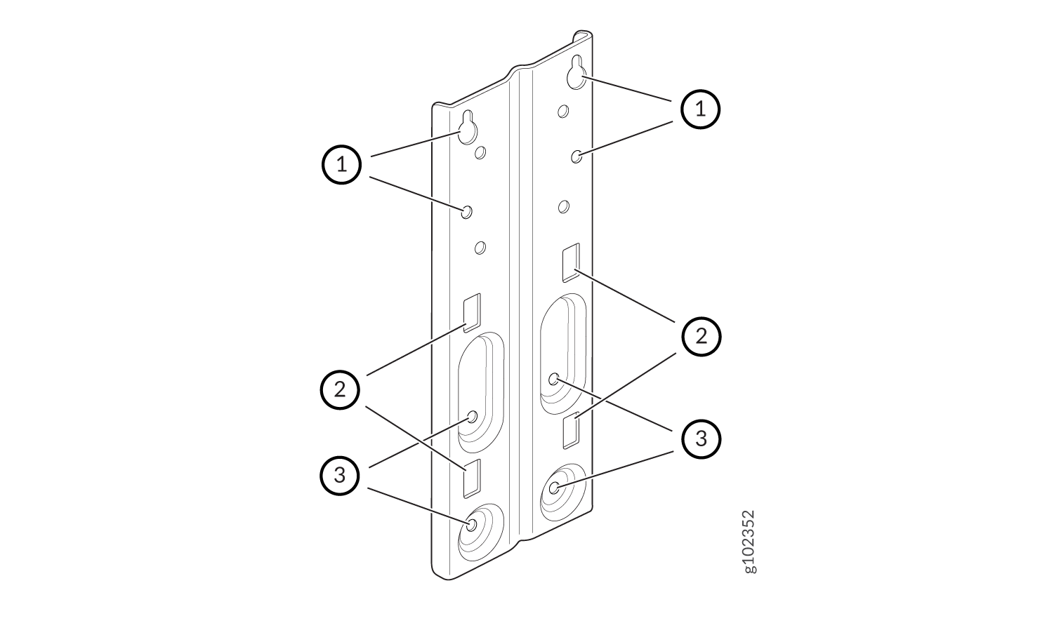
Figure 1 shows the screw holes to use for mounting on a wall and pole.
Figure 1: APOUTBR-FM Flush Mount Bracket APOUTBR-FM Flush Mount Bracket
1—Screw holes to use for mounting an AP63 on a wall 2—Holes to use for attaching hose clamps
3—Screw holes to use for attaching the bracket to an AP63  

Mounting Brackets for Articulating Mount Method

The mounting accessories for articulating mounting include the following:

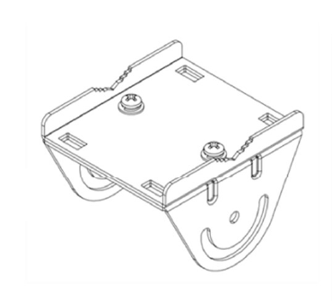
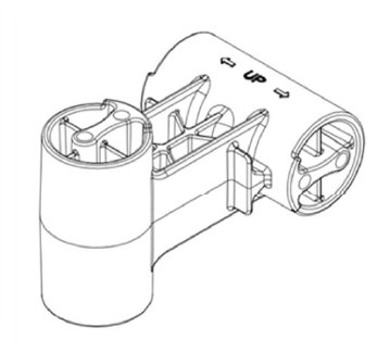
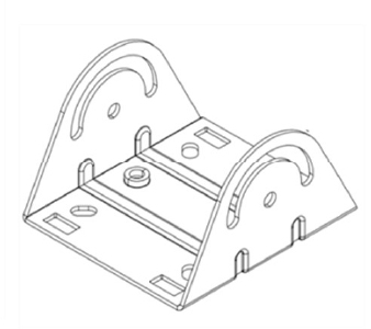
  • Three mounting brackets (part number: APOUTBR-ART2):

    • Mounting bracket 1

    • Mounting bracket 2

    • Mounting bracket 3

  • Four M6x10mm screws

  • Four bolts and nuts

Connect the Grounding Cable

We recommend that you ground the AP before mounting it on a wall or pole. The AP63 has a single-hole protective grounding terminal on the rear. Use this grounding terminal to ground the AP.

To ground the AP63:

  1. Remove the screw.
  2. Place the grounding lug attached to the grounding cable over the grounding terminal.
  3. Secure the grounding cable lug to the grounding terminal with the screw.

Mount the AP63 on a Wall (Flush Mount)

To flush mount the AP63 on a wall:
  1. Drill four holes on the wall based on the location of holes marked with callout #1 in Figure 1
  2. Insert screws in the two upper holes. Do not tighten the screws fully.
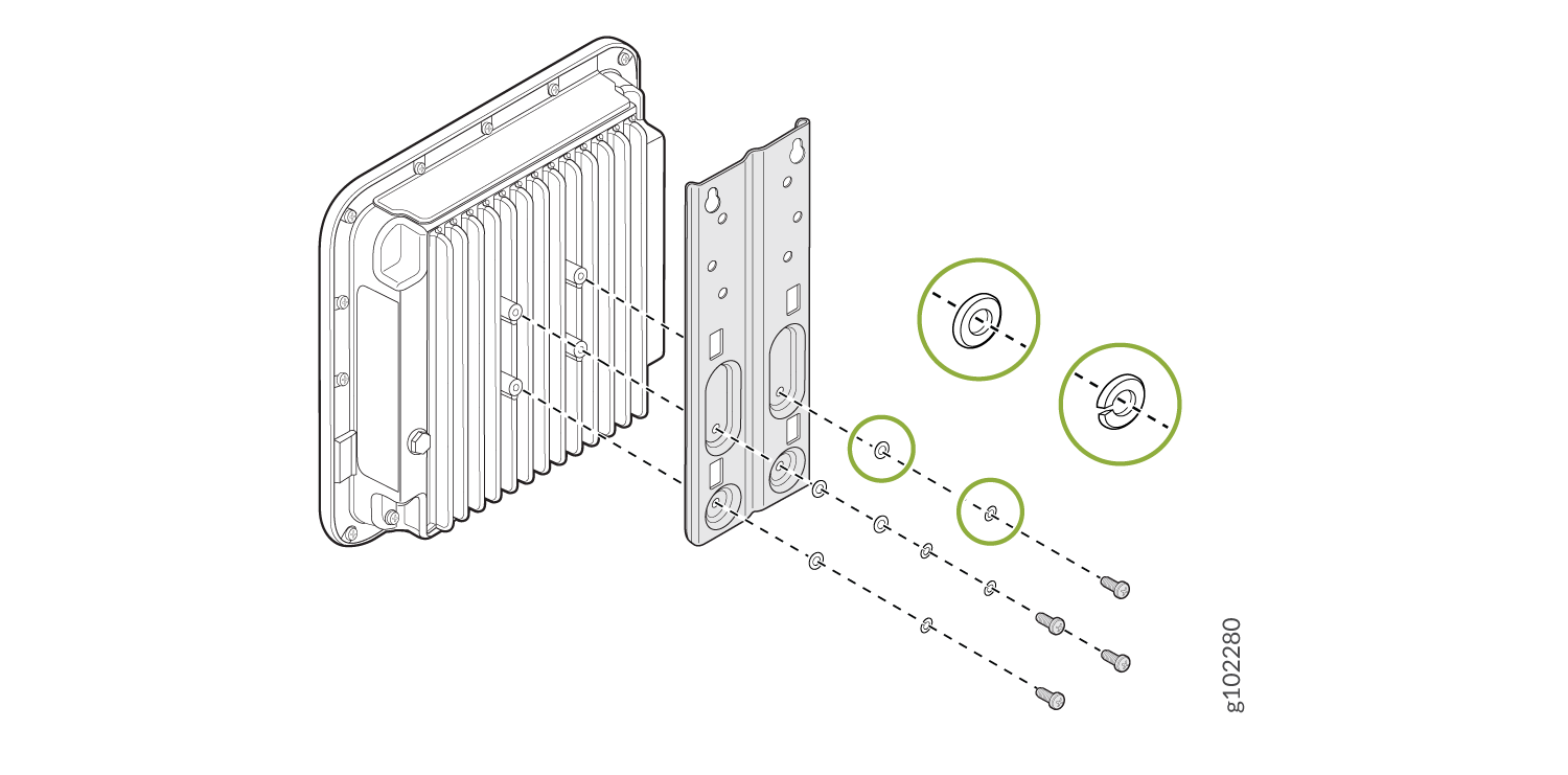
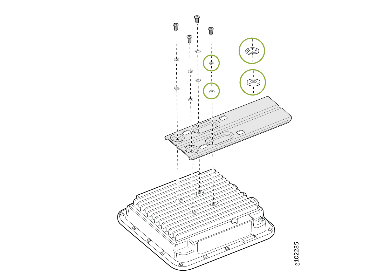
  3. Attach the APOUTBR-FM flush mount bracket to the AP by using the four screws, washers, and lock washers provided along with the AP. Use the bracket screw holes marked with callout #3 in Figure 1.
    Figure 2: Attach the APOUTBR-FM Flush Mount Bracket to an AP63 Attach the APOUTBR-FM Flush Mount Bracket to an AP63
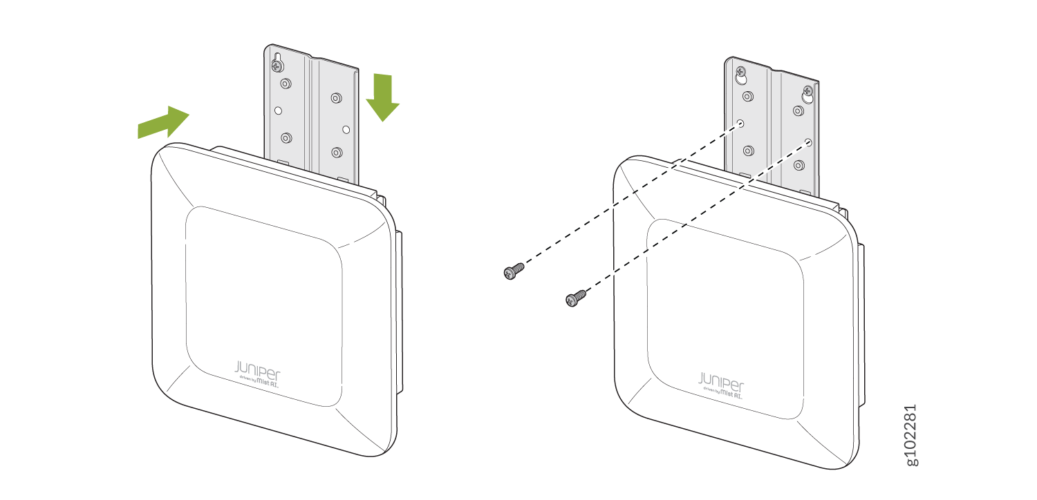
  4. Position the AP such that the two screws that you inserted in Step 1 fit into the holes in the bracket. Slide the AP downward so that the screws lock in place.
    Figure 3: Mount an AP63 on a Wall (Flush Mount) Mount an AP63 on a Wall (Flush Mount)
  5. Insert the other two screws and then tighten all the four screws.

Mount the AP63 on a Pole (Flush Mount)

To flush mount the AP63 on a pole:
  1. Attach the hose clamps to the APOUTBR-FM flush mount bracket. Use a screwdriver to release the hose clamps and then pass the hose clamps through the slots in the flush mount bracket.
    Figure 4: Attach Hose Clamps to the APOUTBR-FM Flush Mount Bracket Attach Hose Clamps to the APOUTBR-FM Flush Mount Bracket
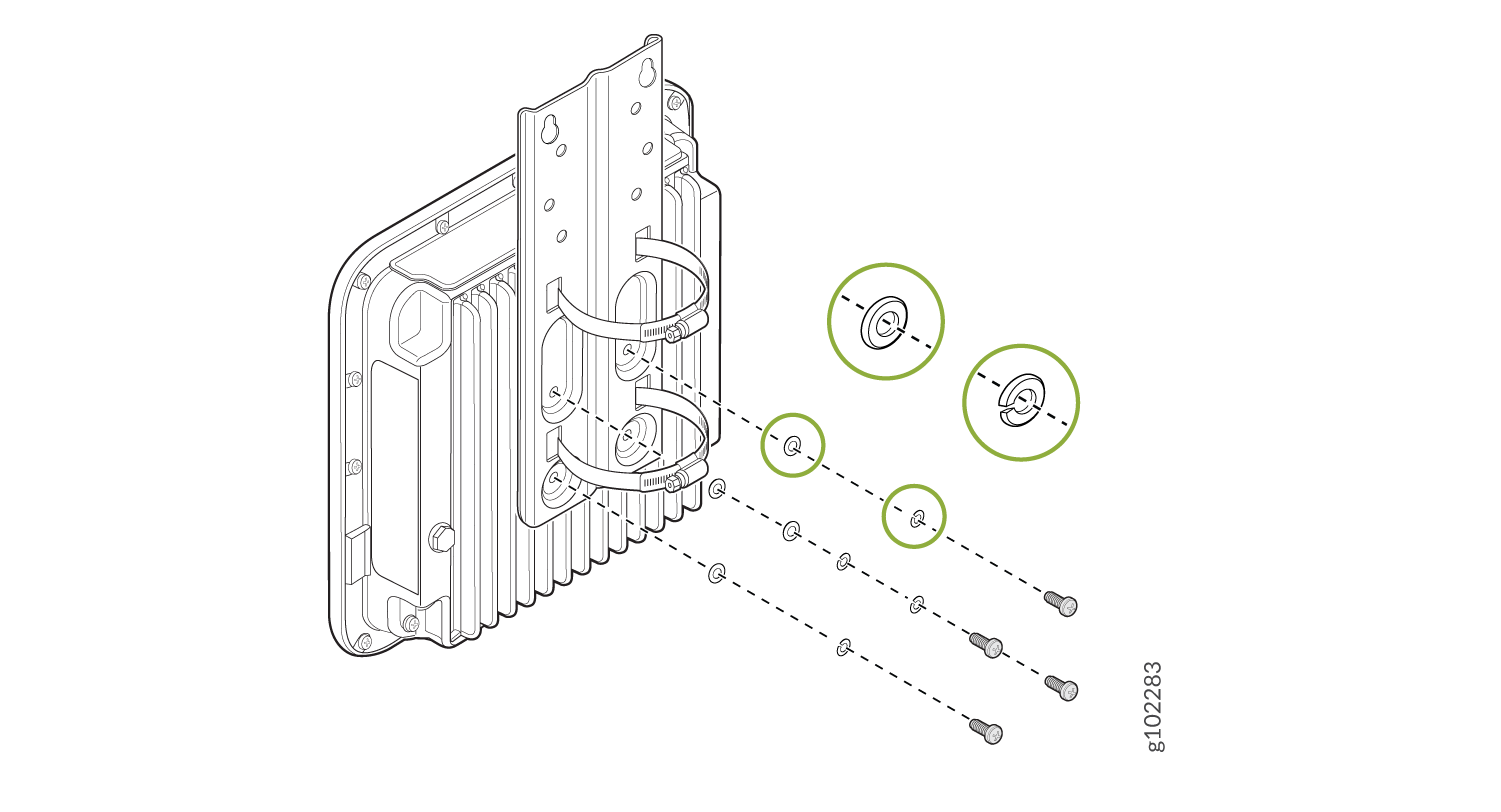
  2. Attach the APOUTBR-FM flush mount bracket to the AP by using the four screws, washers, and lock washers provided along with the AP.
    Figure 5: Attach the APOUTBR-FM Flush Mount Bracket to an AP63 Attach the APOUTBR-FM Flush Mount Bracket to an AP63
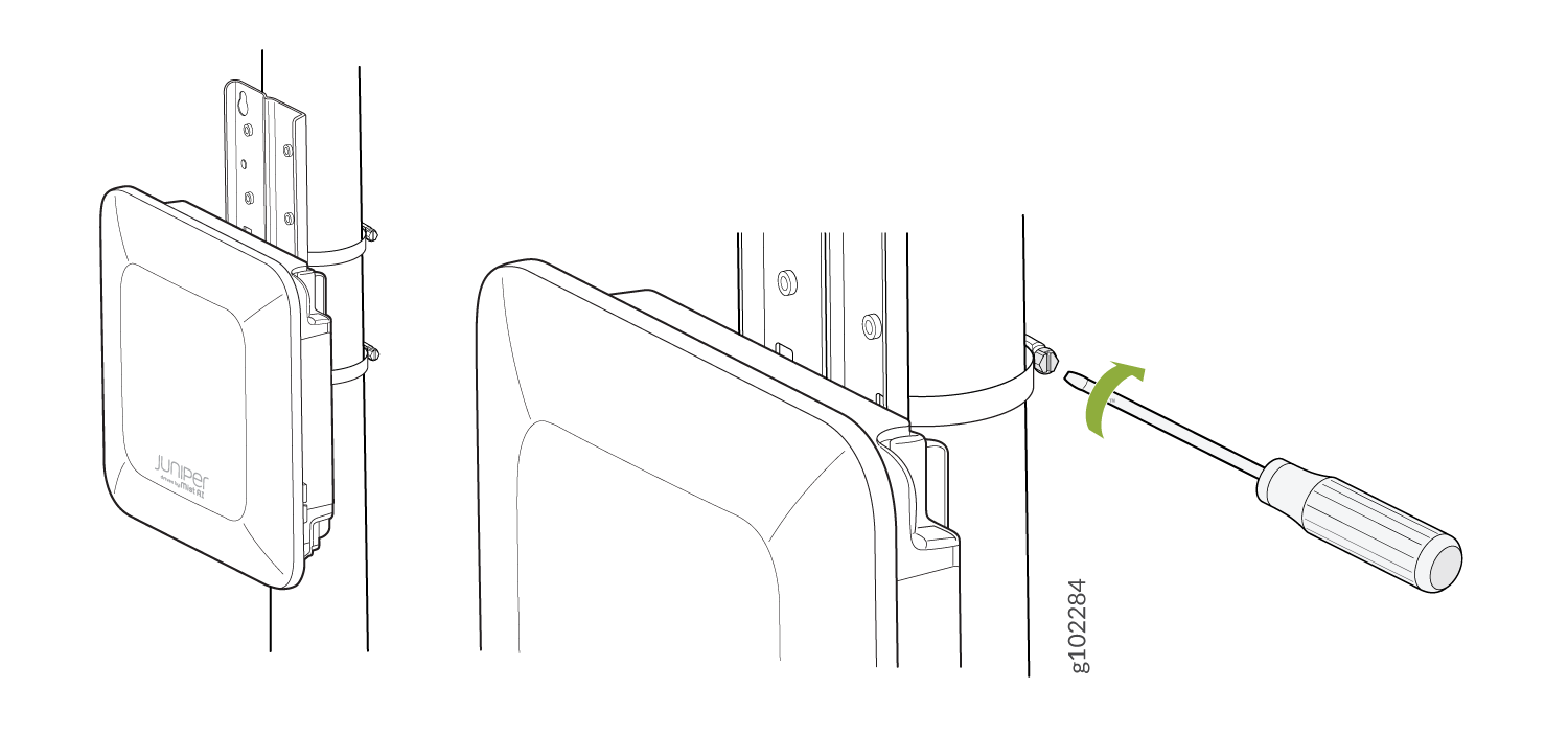
  3. Mount the AP on the pole. Wind the open end of the hose clamps around the pole and tighten the hose clamp screws by using a screwdriver. Tighten the screws until the AP and bracket assembly are secured in place.
    Figure 6: Mount an AP63 on a Pole (Flush Mount) Mount an AP63 on a Pole (Flush Mount)

Mount the AP63 on a Wall (Articulating Mount)

To mount the AP63 on a wall using the articulating mount bracket:
  1. Attach the flush mount bracket APOUTBR-FM to the AP by using the four M6x16mm screws, washers, and lock washers.
    Figure 7: Attach the APOUTBR-FM Flush Mount Bracket to an AP63 Attach the APOUTBR-FM Flush Mount Bracket to an AP63
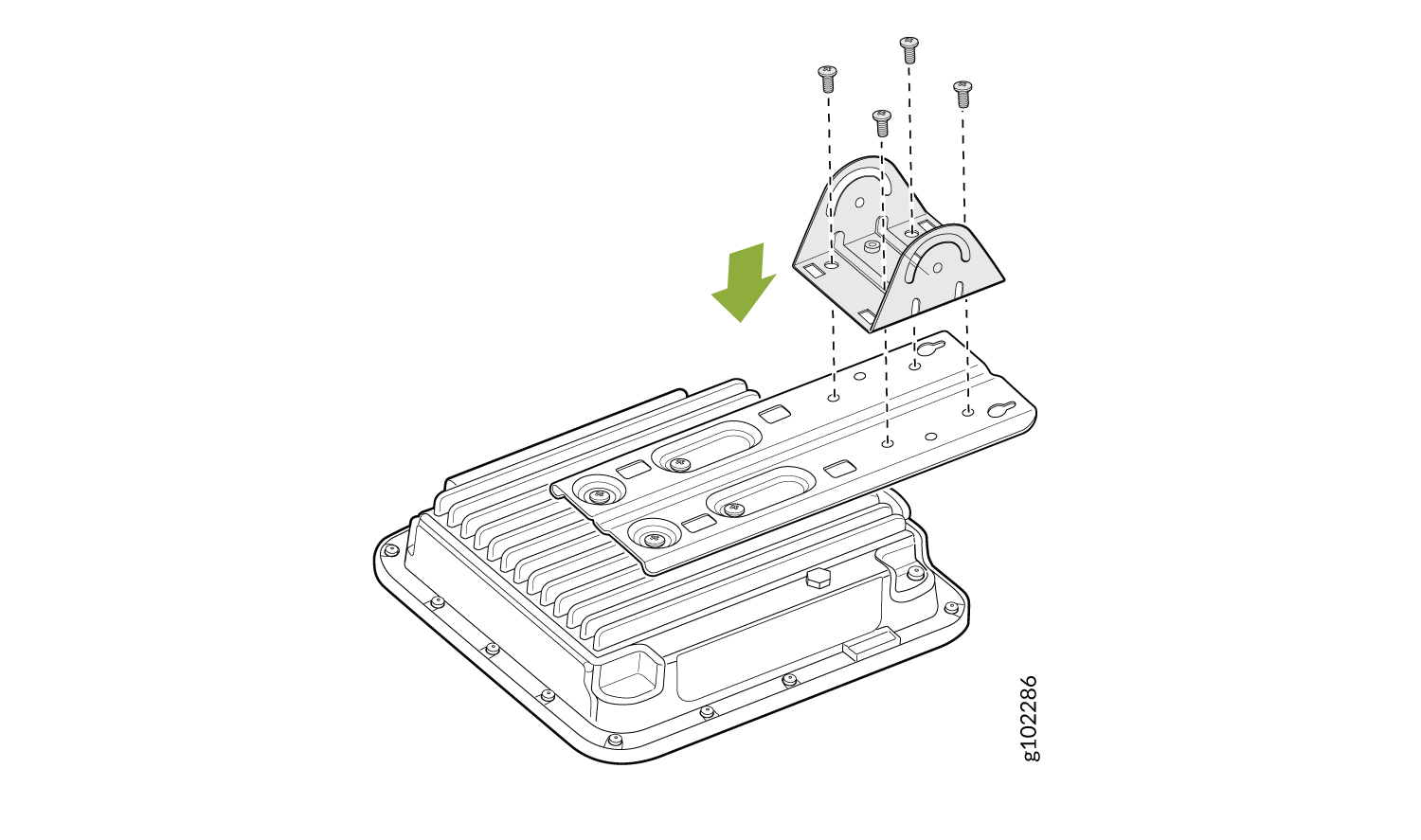
  2. Attach the APOUTBR-ART2 mounting bracket 3 to the flush mount bracket APOUTBR-FM by using the four M6x10mm screws.
    Figure 8: Attach the APOUTBR-ART2 Mounting Bracket 3 to the APOUTBR-FM Flush Mount Bracket Attach the APOUTBR-ART2 Mounting Bracket 3 to the APOUTBR-FM Flush Mount Bracket
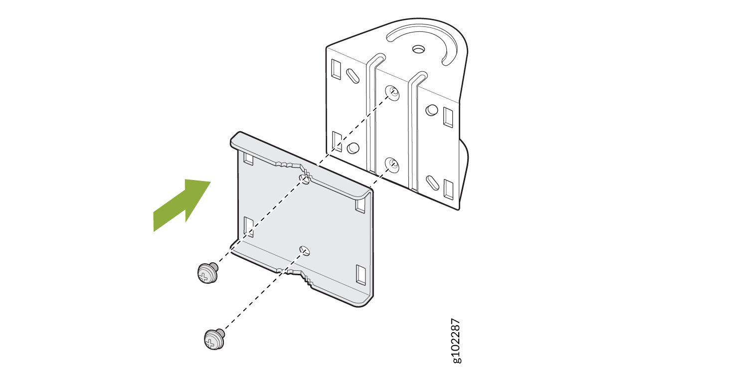
  3. Disassemble the APOUTBR-ART2 mounting bracket 1 by removing the two screws.
    Figure 9: Disassemble the APOUTBR-ART2 Mounting Bracket 1 Disassemble the APOUTBR-ART2 Mounting Bracket 1
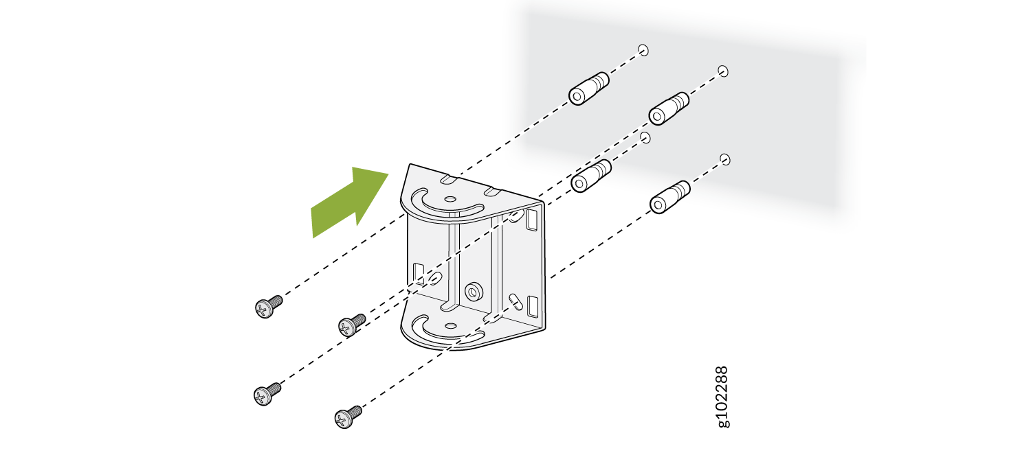
  4. Install the APOUTBR-ART2 mounting bracket 1 on the wall using four screws.
    Figure 10: Install the APOUTBR-ART2 Mounting Bracket 1 on a Wall Install the APOUTBR-ART2 Mounting Bracket 1 on a Wall
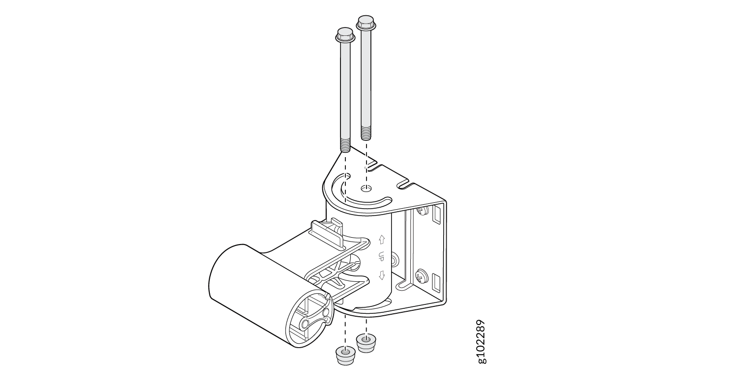
  5. Attach the APOUTBR-ART2 mounting bracket 2 to the mounting bracket 1 by using two bolts and nuts. Orient the side with "← UP → " as shown in Figure 11.
    Figure 11: Attach the APOUTBR-ART2 Mounting Bracket 2 to the Mounting Bracket 1 Attach the APOUTBR-ART2 Mounting Bracket 2 to the Mounting Bracket 1
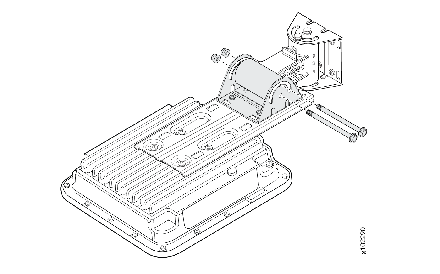
  6. Attach the APOUTBR-ART2 mounting bracket 3 to the mounting bracket 2 by using two bolts and nuts.
    Figure 12: Attach the APOUTBR-ART2 Mounting Bracket 3 to the Mounting Bracket 2 Attach the APOUTBR-ART2 Mounting Bracket 3 to the Mounting Bracket 2

Mount the AP63 on a Pole (Articulating Mount)

To mount the AP63 on a wall using the articulating mount bracket:
  1. Attach the flush mount bracket APOUTBR-FM to the AP by using the four M6x16mm screws, washers, and lock washers.
    Figure 13: Attach the APOUTBR-FM Flush Mount Bracket to an AP63 Attach the APOUTBR-FM Flush Mount Bracket to an AP63
  2. Attach the APOUTBR-ART2 mounting bracket 3 to the flush mount bracket APOUTBR-FM by using the four M6x10mm screws.
    Figure 14: Attach the APOUTBR-ART2 Mounting Bracket 3 to the APOUTBR-FM Flush Mount Bracket Attach the APOUTBR-ART2 Mounting Bracket 3 to the APOUTBR-FM Flush Mount Bracket
  3. Attach the hose clamps to the APOUTBR-ART2 Mounting Bracket 1. Use a screwdriver to release the hose clamps and then pass the hose clamps through the slots on the bracket.
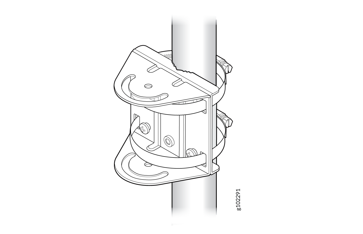
  4. Attach the APOUTBR-ART2 mounting bracket 1 to the pole. Wind the open end of the hose clamps around the pole and tighten the hose clamp screws by using a screwdriver. Tighten the screws until the bracket is secured in place.
    Figure 15: Attach the APOUTBR-ART2 Mounting Bracket 1 to a Pole Attach the APOUTBR-ART2 Mounting Bracket 1 to a Pole
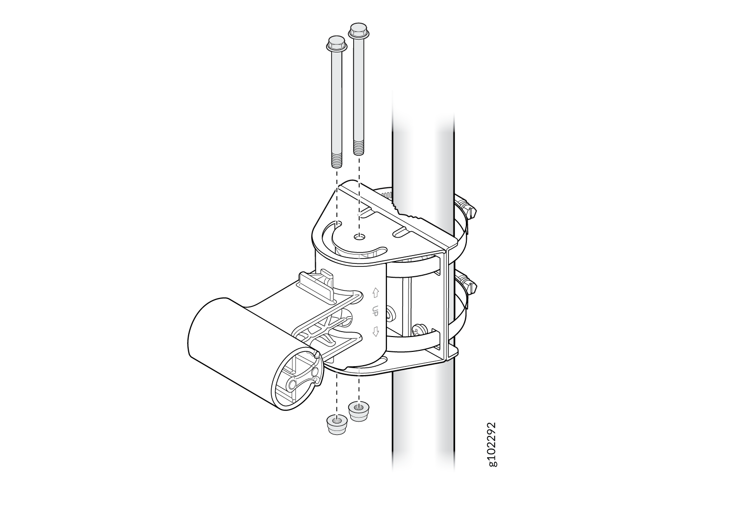
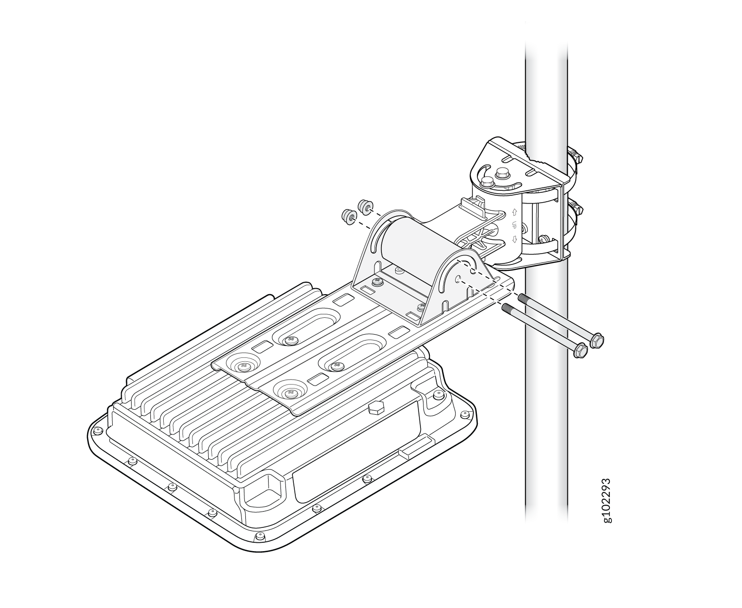
  5. Attach the APOUTBR-ART2 mounting bracket 2 to the mounting bracket 1 by using two bolts and nuts included in the bracket kit. Orient the side with the label ← UP → as shown in Figure 16.
    Figure 16: Attach the APOUTBR-ART2 Mounting Bracket 2 to the Mounting Bracket 1 Attach the APOUTBR-ART2 Mounting Bracket 2 to the Mounting Bracket 1
  6. Attach the APOUTBR-ART2 mounting bracket 3 to the mounting bracket 2 by using two bolts and nuts included in the bracket kit.
    Figure 17: Attach the APOUTBR-ART2 Mounting Bracket 3 to the Mounting Bracket 2 Attach the APOUTBR-ART2 Mounting Bracket 3 to the Mounting Bracket 2

Connect an RJ-45 Cable Gland

Use an RJ-45 cable gland when you connect an RJ-45 cable to the AP. The cable gland helps secure the RJ-45 cable and protects the cable from damage. To connect an RJ-45 cable using the cable gland:
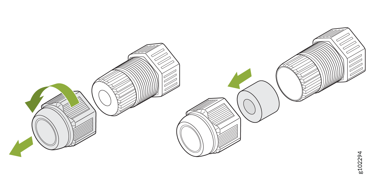
  1. Disassemble the cable gland:
    1. Remove the cable gland nut by turning it counter-clockwise.

    2. Remove the blue seal. Ensure that you select the correct seal. The cable gland has two seals—a blue seal (7 mm through 9.5 mm diameter) and a red seal (5.5 mm through 7 mm diameter).

    Figure 18: Disassemble an RJ-45 Cable Gland Disassemble an RJ-45 Cable Gland
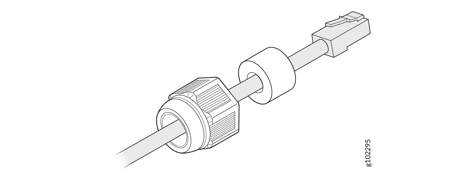
  2. Insert the RJ-45 cable through the cable gland:
    1. Open the seal and insert the RJ-45 cable through the nut and the seal.

      Figure 19: Insert the RJ-45 Cable Through the Nut and the Seal of the Cable Gland Insert the RJ-45 Cable Through the Nut and the Seal of the Cable Gland
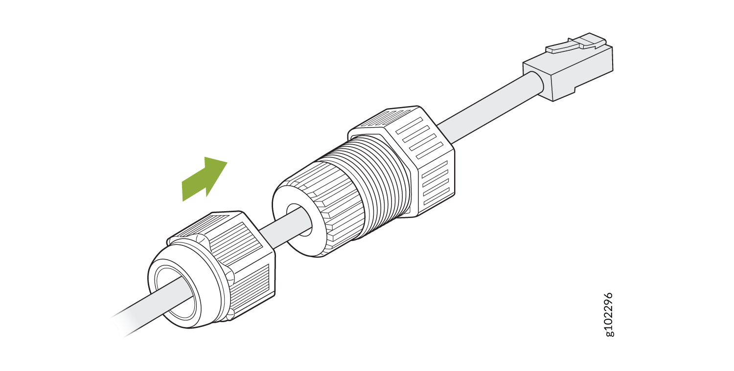
    2. Push the RJ-45 cable through the cable gland. Push the seal into the cable gland and loosely tighten the nut.

      Figure 20: Push the RJ-45 Cable Through the Cable Gland Push the RJ-45 Cable Through the Cable Gland
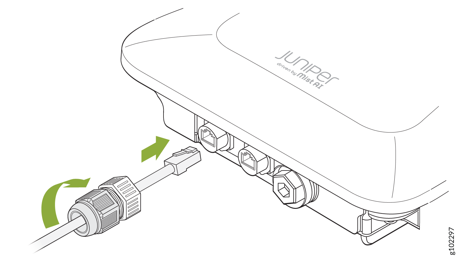
  3. Connect the RJ-45 cable to the AP port. Attach the cable gland to the AP and tighten it with a torque of 10–12 kg-cm. Then, fully tighten the nut to the cable gland with a torque of 7–10 kg-cm.
    Figure 21: Attach a Cable Gland to the AP63 Attach a Cable Gland to the AP63