EX4100-H Power System
This topic details the power systems (PSUs) and their specifications for the EX4100-H switches.
AC Power Supply Unit in EX4100-H Switches
The EX4100-H-12MP uses 340 W AC and 340 W DC external fanless power supply units (PSUs). You can connect up to two PSUs to the switch.
This device is designed to support overvoltage category II (OVC II). If the equipment is subjected to transient voltages greater than OVC II, it will need additional external protection. Ensure that the component you use for this external protection complies with IEC 61643/UL 1449 based on the local code.
EX4100-H switches are designed for Pollution DEGREE II
You can connect the EX4100-H-12MP switch to any one of the following:
- One external 340 W AC PSU
- One external 340 W DC PSU
- Two external 340 W AC PSUs
- Two external 340 W DC PSUs
- One external 340 W AC PSU and one external 340 W DC PSU
The AC PSU for the EX4100-H-24MP and EX4100-H-24F switch is a FRU PSU.
- Characteristics of the AC PSU
- Specifications of the AC PSUs
- PoE Budget Planning
- Specifications of the Power Cord for AC PSUs for EX4100-H Switches
Characteristics of the AC PSU
-
The EX4100-H-12MP uses an external 340 W AC PSU.
-
The EX4100-H-24MP uses a FRU 340 W AC PSU.
-
The EX4100-H-24F uses a FRU 90 W AC PSU.
Refer EX4100-H Power System to check the EX4100-H models and their respective external PSUs or FRU PSUs.
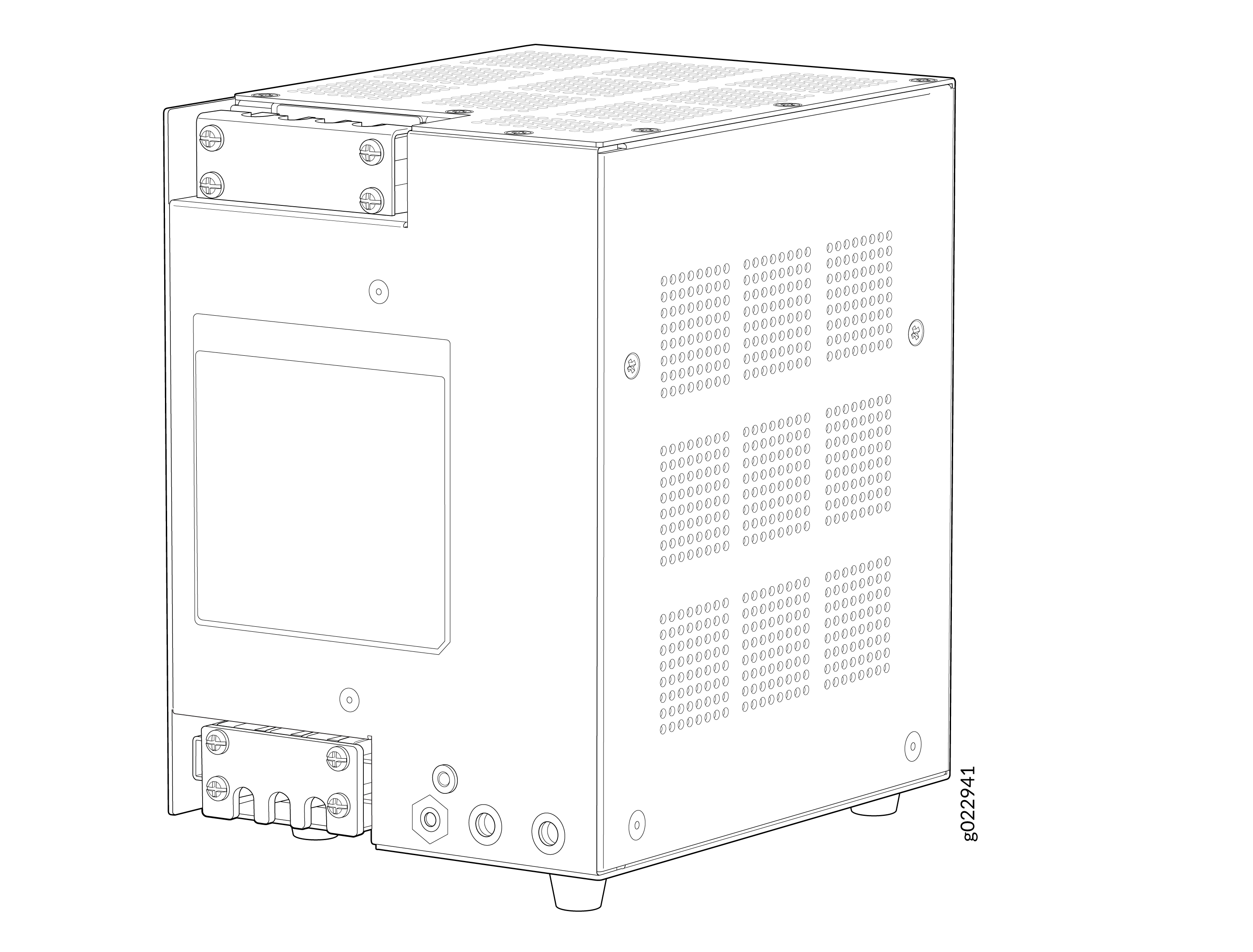
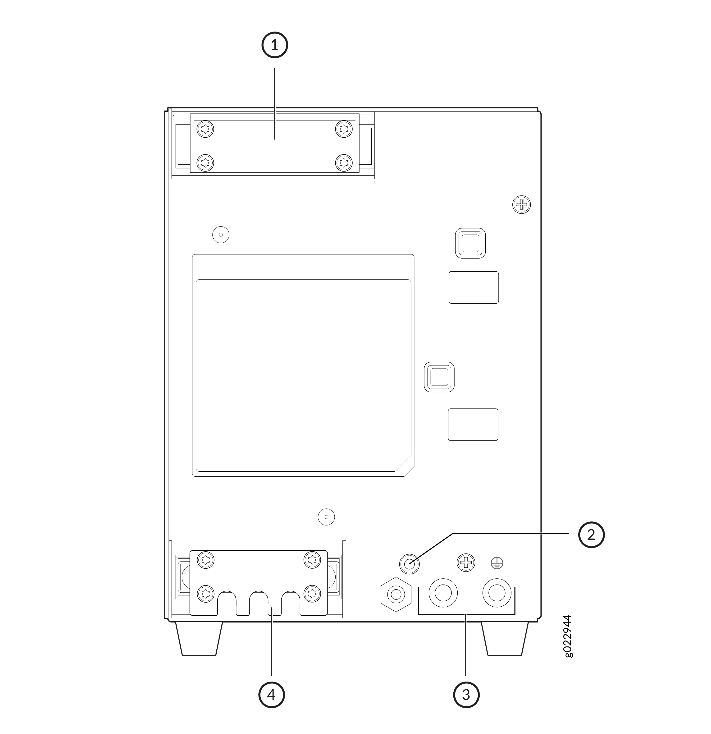
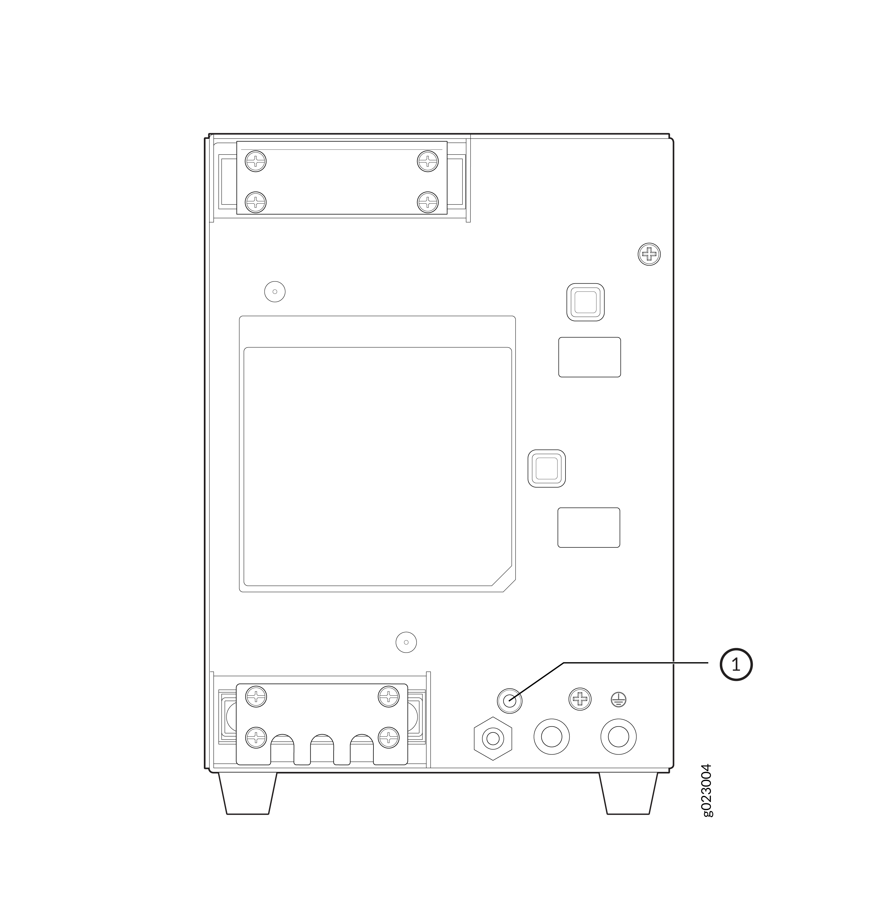
1 — PSU power output terminal | 3 — PSU grounding points |
2 — PSU LED | 4 — PSU power input terminal |


Table 1 lists details of the 340 W AC external PSUs used in EX4100-H-12MP switches. Refer Figure 9 for the external PSU LED colors and statuses.
|
Details |
340 W AC PSU |
|
|---|---|---|
|
Model number |
|
|
|
AC appliance inlet Note:
Each AC appliance inlet requires a dedicated AC power source. |
Number |
1 |
|
Type |
Terminal block |
|
|
Power supply status LED (OUT_OK) |
One single bi-color LED (green and amber) |
|
|
Details |
340 W AC PSU |
|
|---|---|---|
|
Model number |
|
|
|
Power supply status LED (OUT_OK) |
One single bi-color LED (green and amber) |
|
|
Details |
90 W AC PSU |
|
|---|---|---|
|
Model number |
|
|
|
Power supply status LED (OUT_OK) |
One single bi-color LED (green and amber) |
|
Specifications of the AC PSUs
-
Table 4 provides the PSU specifications of the 340 W AC PSUs.
|
Item |
Specification |
|---|---|
|
Input voltage range and frequency |
100-240 V, 50-60 HZ |
|
Output power |
340 W |
|
Item |
Specification |
|---|---|
|
Input voltage range and frequency |
100-240 V, 50-60 HZ |
|
Output power |
340 W |
|
Item |
Specification |
|---|---|
|
Input voltage range and frequency |
100-240 V, 50-60 HZ |
|
Output power |
90 W |
PoE Budget Planning
Table 7 shows the PoE budget planning details in EX4100-H-12MP switch models.
|
Model |
System Budget |
PoE Budget |
Total Budget |
PSU |
|---|---|---|---|---|
|
EX4100-H-12MP with one PSU |
66 W |
240 W |
306 W |
340 W |
|
EX4100-H-12MP with two PSU |
66 W |
360 W |
426 W |
680 W |
Table 8 shows the PoE budget planning details in EX4100-H-24MP switch models.
|
Model |
System Budget |
PoE Budget |
Total Budget |
PSU |
|---|---|---|---|---|
|
EX4100-H-24MP with one PSU |
81 W |
240 W |
321 W |
340 W |
|
EX4100-H-24MP with two PSU |
81 W |
370 W |
451 W |
680 W |
Specifications of the Power Cord for AC PSUs for EX4100-H Switches
A detachable AC power cord is supplied with the AC PSUs. The coupler is a custom lug-type. The plug end of the power cord fits into the power source outlet that is standard for your geographical location.
The AC power cord provided with each power supply is intended for use with that PSU only and not for any other use.
The power cord of spare PSUs is separately orderable.
In North America, AC power cords must not exceed 4.5 m (approximately 14.75 ft) in length, to comply with National Electrical Code (NEC) Sections 400-8 (NFPA 75, 5-2.2) and 210-52 and with Canadian Electrical Code (CEC) Section 4-010(3).
Table 9 and Table 10 show the AC power cord specifications for supported countries and regions.
|
Country or Region |
Electrical Specifications |
Plug Standards |
Juniper Model Number |
|---|---|---|---|
|
Argentina |
250 VAC, 10 A, 50 Hz |
IRAM 2073 |
CBL-PWR-RGD-RNG-AR |
|
Australia |
250 VAC, 10 A, 50 Hz |
AS/NZS 3112 |
CBL-PWR-RGD-RNG-AU |
|
Brazil |
250 VAC, 10 A, 50 Hz |
NBR 14136 BR/3 |
CBL-PWR-RGD-RNG-BR |
|
China |
250 VAC, 10 A, 50 Hz |
GB 2099/GB1002 |
CBL-PWR-RGD-RNG-CH |
|
Europe (except Italy, Switzerland, and the United Kingdom) |
250 VAC, 10 A, 50 Hz |
CEE(7)VII |
CBL-PWR-RGD-RNG-EU |
|
India Note:
For India, the minimum and maximum temperature rating of the cord is -20 ℃ to +70 ℃ |
250 VAC, 10 A, 50 Hz |
IS1293 |
CBL-PWR-RGD-RNG-IN |
|
Israel |
250 VAC, 10 A, 50 Hz |
SI32 IL/3G |
CBL-PWR-RGD-RNG-IL |
|
Italy |
250 VAC, 10 A, 50 Hz |
CEI 23-50 I/3G |
CBL-PWR-RGD-RNG-IT |
|
Japan |
125 VAC, 12 A, 50 Hz or 60 Hz |
JIS C8303/CNS690 |
CBL-PWR-RGD-RNG-TW |
|
Korea |
250 VAC, 10 A, 50 Hz or 60 Hz |
KSC8305 |
CBL-PWR-RGD-RNG-KR |
|
North America* |
125 VAC, 13 A, 60 Hz |
NEMA 5-15P |
CBL-PWR-RGD-RNG-US |
|
125 VAC, 15 A, 60 Hz |
NEMA 5-15P |
CBL-PWR-RGD-RNG-US |
|
|
South Africa |
250 VAC, 10 A, 50 Hz |
SAN 164/1 ZA/3 |
CBL-PWR-RGD-RNG-SA |
|
Switzerland |
250 VAC, 10 A, 50 Hz |
SEV 1011- 12G |
CBL-PWR-RGD-RNG-SZ |
|
United Kingdom |
250 VAC, 10 A, 50 Hz |
BS1363A/SS145 |
CBL-PWR-RGD-RNG-UK |
|
All countries |
700 mm, 16 AWG, 300 V, 105 C |
NA |
CBL-PWR-RGD-SYS |
CBL-PWR-RGD-SYS is the Juniper Model Number of the interconnecting wire that connects the external 340 W AC PSU to the switch.
|
Country or Region |
Electrical Specifications |
Plug Standards |
Juniper Model Number |
|---|---|---|---|
|
Argentina |
250 VAC, 10A |
IRAM 2073 |
CBL-PWR-RGD-ST-AR |
|
Australia/New Zealand |
250 VAC, 10A |
AS/NZS 3112 |
CBL-PWR-RGD-ST-AU |
|
Brazil |
250 VAC, 10A |
BR/3-IEC53 |
CBL-PWR-RGD-ST-BR |
|
China |
250 VAC, 10A |
GB 2099/GB1002 |
CBL-PWR-RGD-ST-CH |
|
Europe (except Italy, Switzerland, and the United Kingdom) |
250 VAC, 10A |
CEE(7)VII |
CBL-PWR-RGD-ST-EU |
|
India Note:
For India, the minimum and maximum temperature rating of the cord is -20 ℃ to +70 ℃ |
250 VAC, 10A |
3/16-IS694 |
CBL-PWR-RGD-ST-IN |
|
Israel |
250 VAC, 10A |
SI32 IL/3G |
CBL-PWR-RGD-ST-IL |
|
Italy |
250 VAC, 10A |
CEI 23-50 I/3G |
CBL-PWR-RGD-ST-IT |
|
Japan/Taiwan |
125 VAC, 13A |
JIS C8303/CNS690 |
CBL-PWR-RGD-ST-TW |
|
South Korea |
250 VAC, 10A |
KSC8305 |
CBL-PWR-RGD-ST-KR |
|
United States |
125 VAC, 15A |
NEMA 5-15P |
CBL-PWR-RGD-ST-US |
|
South Africa |
250 VAC, 10A |
SAN 164/1 ZA/3 |
CBL-PWR-RGD-ST-SA |
|
Switzerland |
250 VAC, 10A |
SEV 1011- 12G |
CBL-PWR-RGD-ST-SZ |
|
United Kingdom |
250 VAC, 10A |
BS1363A/SS145 |
CBL-PWR-RGD-ST-UK |
Figure 5 illustrates the plug on the power cord for some of the countries or regions listed in Table 9.
Do not use the AC power cord with any other product other than EX4100-H.
Power cords must not block access to switch components.
DC PSU in EX4100-H Switches
The EX4100-H-12MP switches can be powered by external 340 W DC PSUs.
The EX4100-H-24MP and EX4100-H-24F switches use FRU 340 W and 90 W DC PSUs respectively.
- Characteristics of a DC PSU
- Specifications of the DC PSUs Used in EX4100-H Switches
- Specifications of the Power Cord for DC PSUs for EX4100-H Switches
Characteristics of a DC PSU
The DC PSUs for EX4100-H-12MP switches are available in the 340 W fanless model.
The FRU DC PSU for EX4100-H-24MP is available in the 340 W fanless model. The FRU DC PSU for EX4100-H-24F is available in the 90 W fanless model.
The FRU DC PSU for EX4100-H-24F is available in the 90 W fanless model.
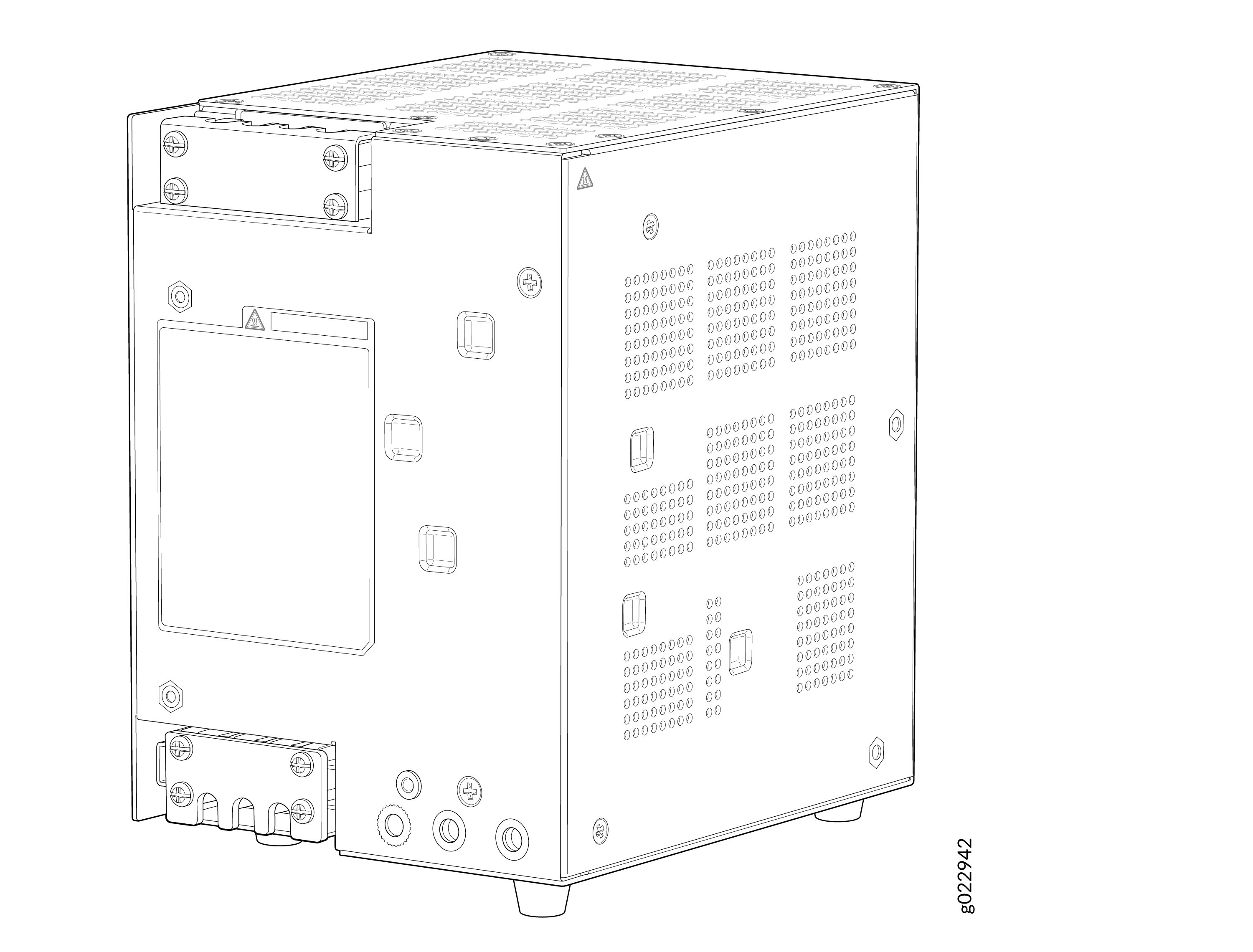


Table 11 lists the details of the 340 W DC PSUs used in EX4100-H-12MP switches.
|
Details |
340 W DC PSU |
|
|---|---|---|
|
Model number |
|
|
|
DC appliance inlet Note:
Each DC appliance inlet requires a dedicated power source. |
Number |
1 |
|
Type |
DC input power connector |
|
|
Power supply status LED (OUT_OK) |
One single bi-color LED (green and amber) |
|
Table 2 lists the details of the FRU 340 W DC PSUs used in EX4100-H-24MP switches.
|
Details |
340 W DC PSU |
|
|---|---|---|
|
Model number |
|
|
|
Power supply status LED (OUT_OK) |
One single bi-color LED (green and amber) |
|
Table 3lists the details of the FRU 90 W DC PSUs used in EX4100-H-24F switches.
|
Details |
90 W DC PSU |
|
|---|---|---|
|
Model number |
|
|
|
Power supply status LED (OUT_OK) |
One single bi-color LED (green and amber) |
|
Specifications of the DC PSUs Used in EX4100-H Switches
Table 14 provides the power supply specifications of the DC power supplies.
|
Item |
Specification |
DC PSU |
|---|---|---|
|
DC input voltage and range |
Range at input of terminal block: 20.4 VDC to 72 VDC DC input voltage nominal: +24V/-48V/-60VDC |
EX4100-H-12MP-DC-PSU (340 W external) used in EX4100-H-12MP |
|
DC input voltage and range |
Range at input of terminal block: 20.4 VDC to 72 VDC DC input voltage nominal: +24V/-48V/-60VDC |
EX4100-H-24F-DC-PSU (90 W FRU) used in EX4100-H-24F |
The wire gauge measurement of the external 340 W DC PSU of the EX4100-H-12MP is 12 AWG with temperature rating of wire 90C or as per country code.
Specifications of the Power Cord for DC PSUs for EX4100-H Switches
Table 15 provides the DC power cord specification of the external 340-W PSU of the EX4100-H-12MP Switch. Table 16 provides the DC power cord specification of the FRU 340-W PSU and 90-W PSU of the EX4100-H-24MP and EX4100-H-24F switches respectively.
|
Country or Region |
Specifications |
Juniper Model Number |
|---|---|---|
|
All countries |
4 meters, 3 wires, 12 AWG, -40℃~85℃ |
CBL-PWR-RGD-DC |
|
Country or Region |
Specifications |
Juniper Model Number |
|---|---|---|
|
All countries |
4 meters, 3 wires, 12 AWG |
CBL-PWR-RGD-ST-DC |
Do not use the DC power cord with any other product other than EX4100-H.
Power cords must not block access to switch components.
The wire gauge measurement of the external 340 W DC PSU of the EX4100-H-12MP is 12 AWG.
Power Supply LEDs in EX4100-H Switches
The PSUs of the EX4100-H switches have one LED that indicates the state of the power supply (see Figure 9).
1 — PSU LED |
The LED locations of the AC and DC PSUs of the EX4100-H-24MP and EX4100-H-24F switches are at the same location as depicted in the following figure although the figure shown is of the FRU 340 W AC PSU of the EX4100-H-24MP switch.

1 — PSU LED |
Table 17 describes the external 340-W AC PSU LED states and power supply conditions.
Table 18 describes the external 340-W DC PSU LED states and power supply conditions.
Table 19 describes the FRU 340-W AC and DC PSU LED states and power supply conditions.
Table 20 describes the FRU 90-W AC and DC PSU LED states and power supply conditions.
|
LED Label |
LED State |
Power Supply Condition |
|---|---|---|
|
OUT_OK |
Green |
12V and 54V output OK |
|
Amber |
Indicates a fault condition even though there is power supply. The following are the possible fault codes:
|
|
|
Off |
No AC input |
|
LED Label |
LED State |
Power Supply Condition |
|---|---|---|
|
OUT_OK |
Green |
12V and 54V output OK |
|
Amber |
Indicates a fault condition even though there is power supply. The following are the possible fault codes:
|
|
|
Off |
No input |
|
LED Label |
LED State |
Power Supply Condition |
|---|---|---|
|
OUT_OK |
Green |
54V output OK or 12V output OK. |
|
Amber |
Indicates a fault condition even though there is power supply. The following are the possible fault codes:
|
|
|
Off |
No AC or DC input |
|
LED Label |
LED State |
Power Supply Condition |
|---|---|---|
|
OUT_OK |
Green |
54V output OK or 12V output OK. |
|
Amber |
Indicates a fault condition even though there is power supply. The following are the possible fault codes:
|
|
|
Off |
No AC or DC input |