Maintaining the EX4650 Power System
Removing a Power Supply from an EX4650 Switch
Before you remove a power supply from an EX4650, ensure that you have taken the necessary precautions to prevent electrostatic discharge (ESD) damage (see Prevention of Electrostatic Discharge Damage).
Ensure that you have the following parts and tools available to remove a power supply from an EX4650:
-
ESD grounding strap
-
Antistatic bag or antistatic mat
-
Phillips (+) screwdriver, number 2 (not provided)
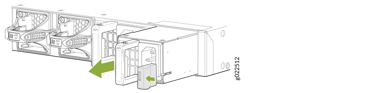
All EX4650 switches are shipped from the factory with two power supplies. Each power supply is a hot-removable and hot-insertable field-replaceable unit (FRU) when the second power supply is installed and running. You can install replacement power supplies in the two slots next to the fan modules without powering off the switch or disrupting the switching function.
Replace the power supply with a new power supply within 1 minute of removal to prevent chassis overheating.
To remove a power supply from an EX4650:
Installing an AC Power Supply in an EX4650 Switch
Before you install an AC power supply in the switch:
-
Ensure that you understand how to prevent electrostatic discharge (ESD) damage. See Prevention of Electrostatic Discharge Damage.
Ensure that you have the following parts and tools available to install the power supply:
Each power supply is a hot-removable and hot-insertable field-replaceable unit (FRU) when the second power supply is installed and running
-
ESD grounding strap
-
Phillips (+) screwdriver, number 2(not provided)
The AC power supply in EX4660 switches is a hot-removable and hot-insertable field-replaceable unit (FRU) installed in the rear panel of the switch: You can remove and replace a power supply without powering off the switch or disrupting switch functions.
Do not mix:
-
AC and DC power supplies in the same chassis.
-
Power supplies with different airflow labels (AIR IN (AFI) and AIR OUT (AFO)) in the same chassis.
-
Fan modules with different airflow labels (AIR IN (AFI) and AIR OUT (AFO)) in the same chassis.
-
Power supplies and fan modules with different airflow labels (AIR IN (AFI) and AIR OUT (AFO)) in the same chassis.
Each power supply must be connected to a dedicated power source outlet.
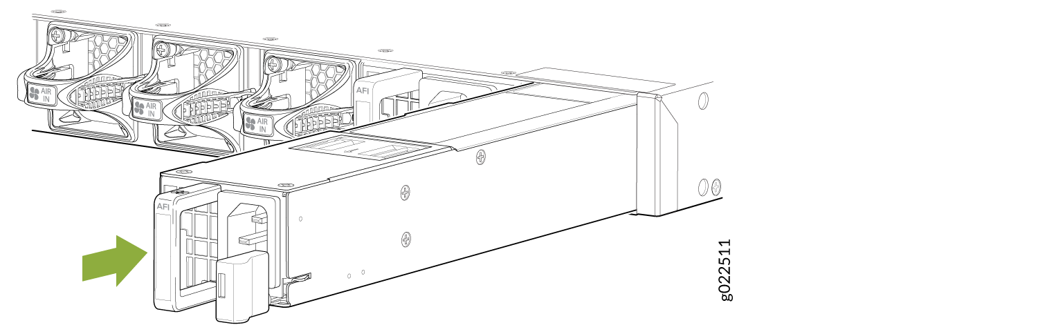
To install an AC power supply in the switch, see Figure 2 shows how to install an AC power supply. The power supply slots are at the right end of the rear panel.
- Ensure that you have the correct power supply. The label on the power supply must match the label AFI or AFO on the installed fan module.
- Attach the ESD grounding strap to your bare wrist, and connect the strap to the ESD point on the chassis.
- Taking care not to touch the power supply pins, leads, or solder connections, remove the power supply from the bag.
- Using both hands, place the power supply in the power supply slot on the rear panel of the switch, and slide it in until it is fully seated and the ejector lever fits into place.