ON THIS PAGE
MX10004 Power System Maintenance
Maintaining a Juniper Networks MX10004 router includes replacing power supplies. Replacing includes removing a failed power supply and installing a functional power supply.
The MX10004 routers support AC, DC, high-voltage alternating current (HVAC), and high-voltage direct current (HVDC) power supplies. All power supply models are hot-insertable and hot-removeable field-replaceable units (FRUs). You can install up to three power supplies in the rear of the chassis in the slots provided along the left side.
The following topics describe how to install and remove the power supplies in an MX10004.
Use the same type of power supply in all slots. Do not mix power supply models in the same chassis.
See the heat symbol  .
Wear heat-resistant hand gloves while accessing the fan tray and power supply.
Install a JNP10K-PWR-AC3 Power Supply
Use the same type of power supply in all slots. Do not mix power supply models in a production chassis. The only time you are allowed to have two models concurrently running in a system is when you are in the process of swapping out all JNP10K-PWR-AC/JNP10K-PWR-AC2 power supplies with all JNP10K-PWR-AC3 power supplies.
Protect yourself from severe burns by wearing heat-protective gloves when removing a running JNP10K-PWR-AC3 power supply from the chassis. The power supply can reach temperatures of 158 °F through 176 °F (70 °C through 80 °C) when the equipment is On.
Before you install a JNP10K-PWR-AC3 power supply in the chassis:
-
Ensure that you have followed all safety warnings and cautions.
-
Ensure that you understand how to prevent ESD damage. See Prevention of Electrostatic Discharge Damage.
-
If the AC power source outlets have a power switch, set them to the off (O) position. Ensure that you have the following parts and tools available to install the JNP10K-PWR-AC3 power supply:
-
Electrostatic discharge (ESD) grounding strap
-
Phillips (+) screwdriver, number 1
-
Power cables appropriate for your geographical location (for low-voltage installations) or input amperage (for high-voltage installations). See MX10004 Power Cable Specifications.
-
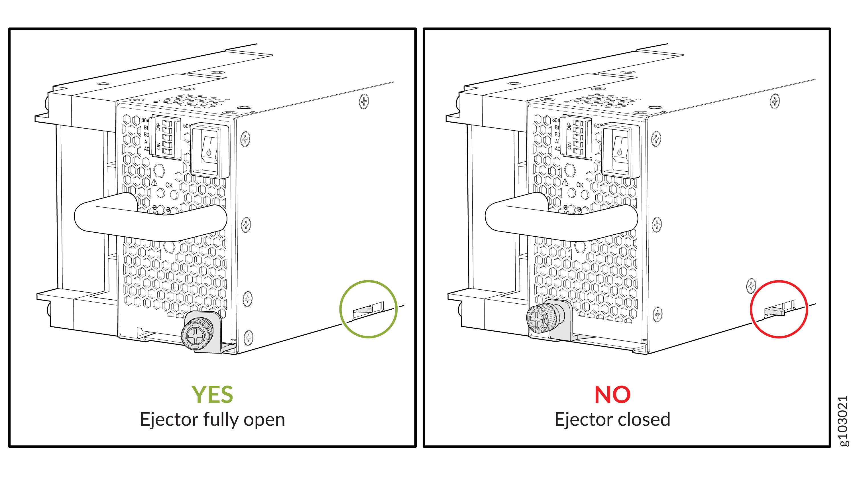
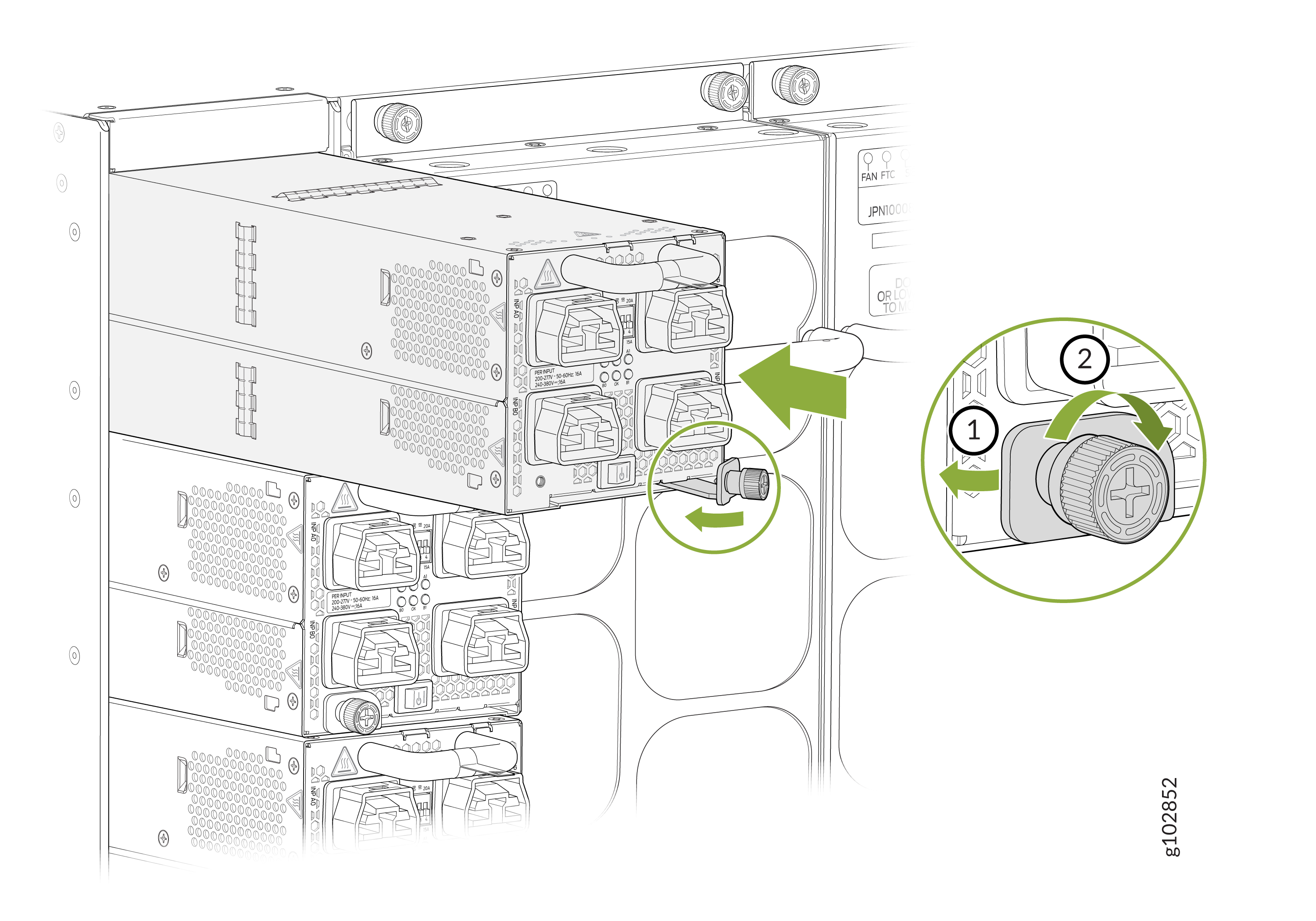
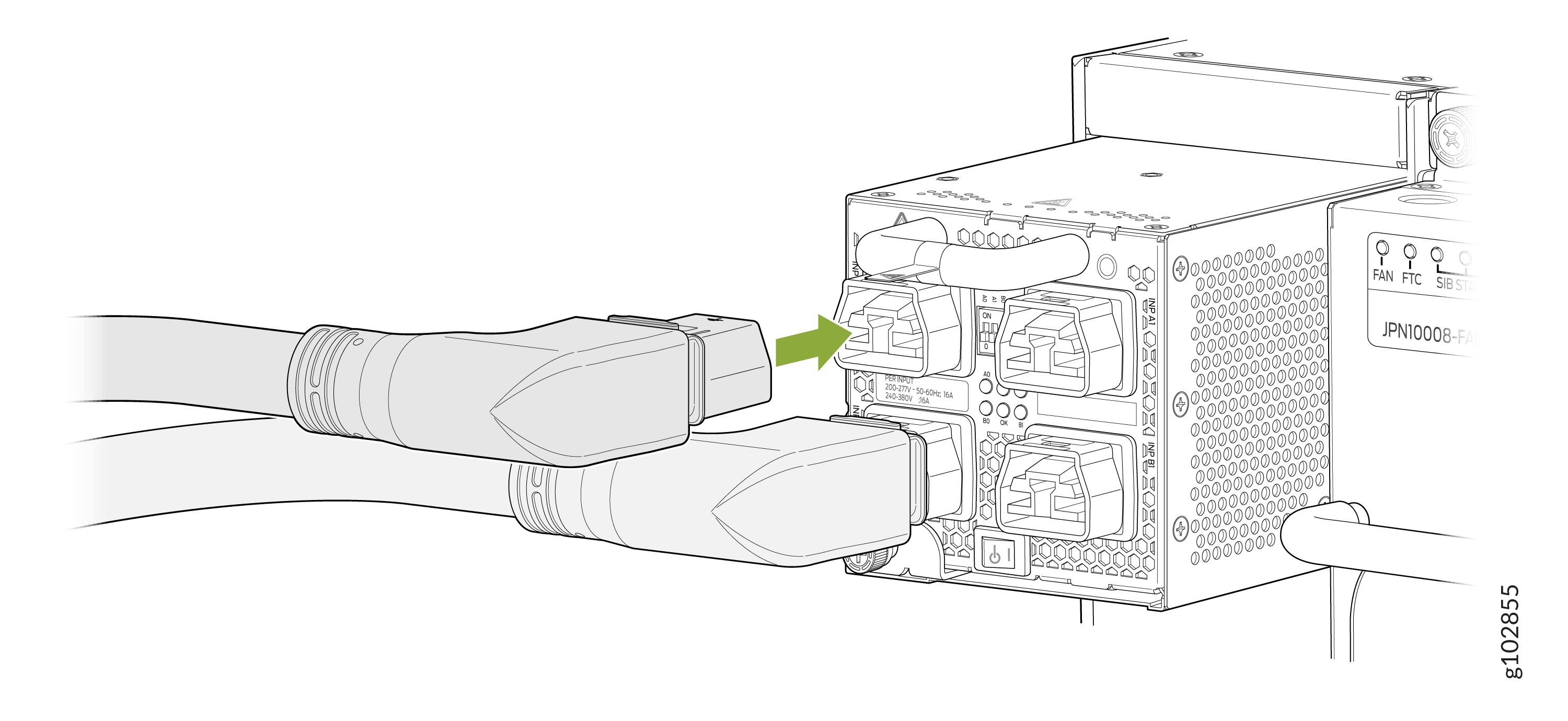
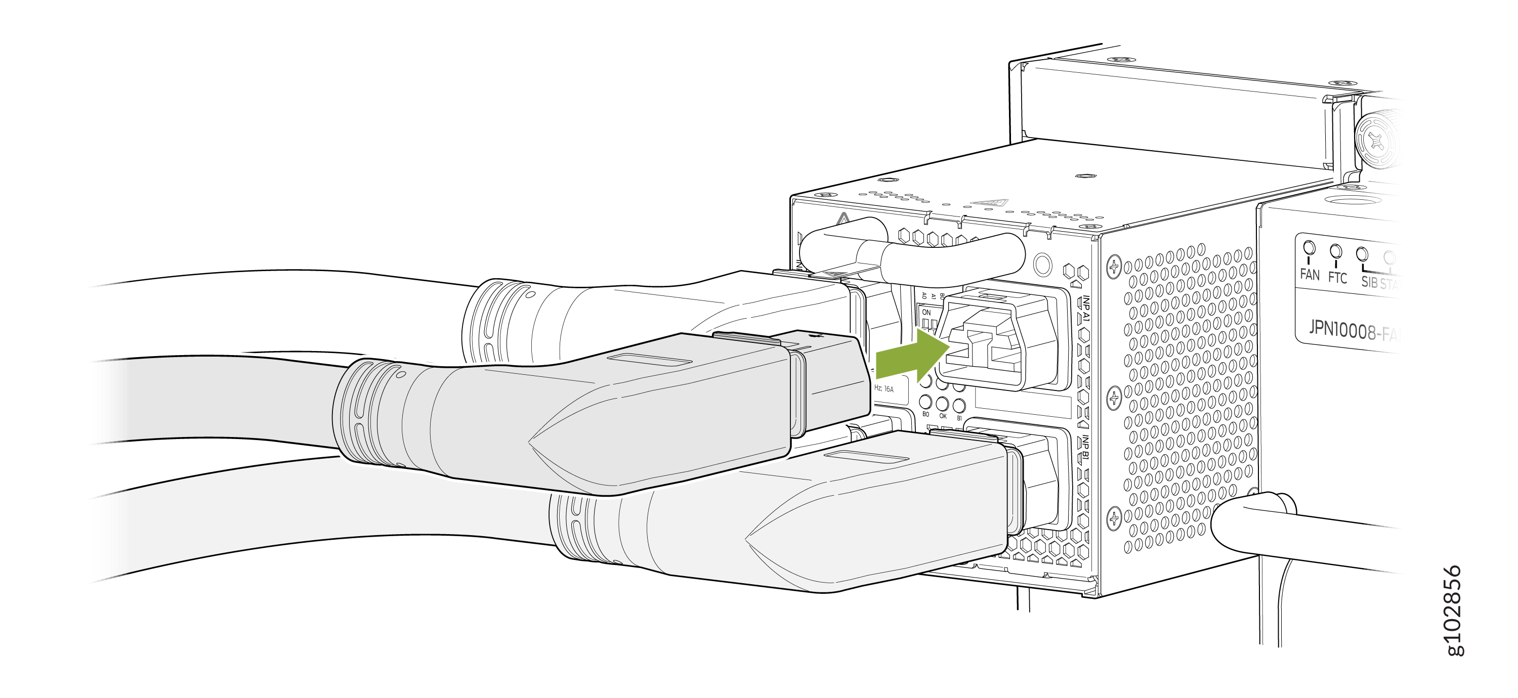
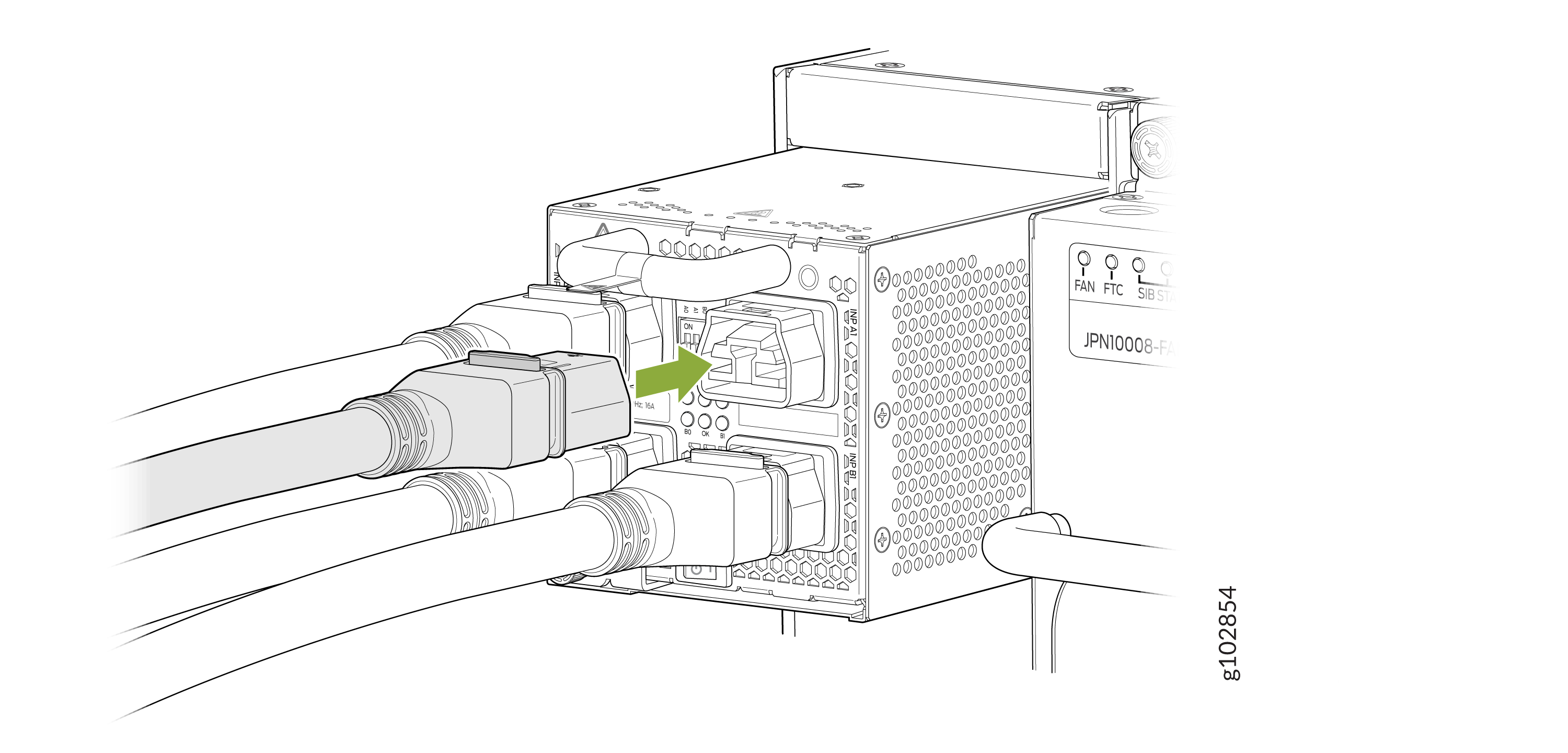
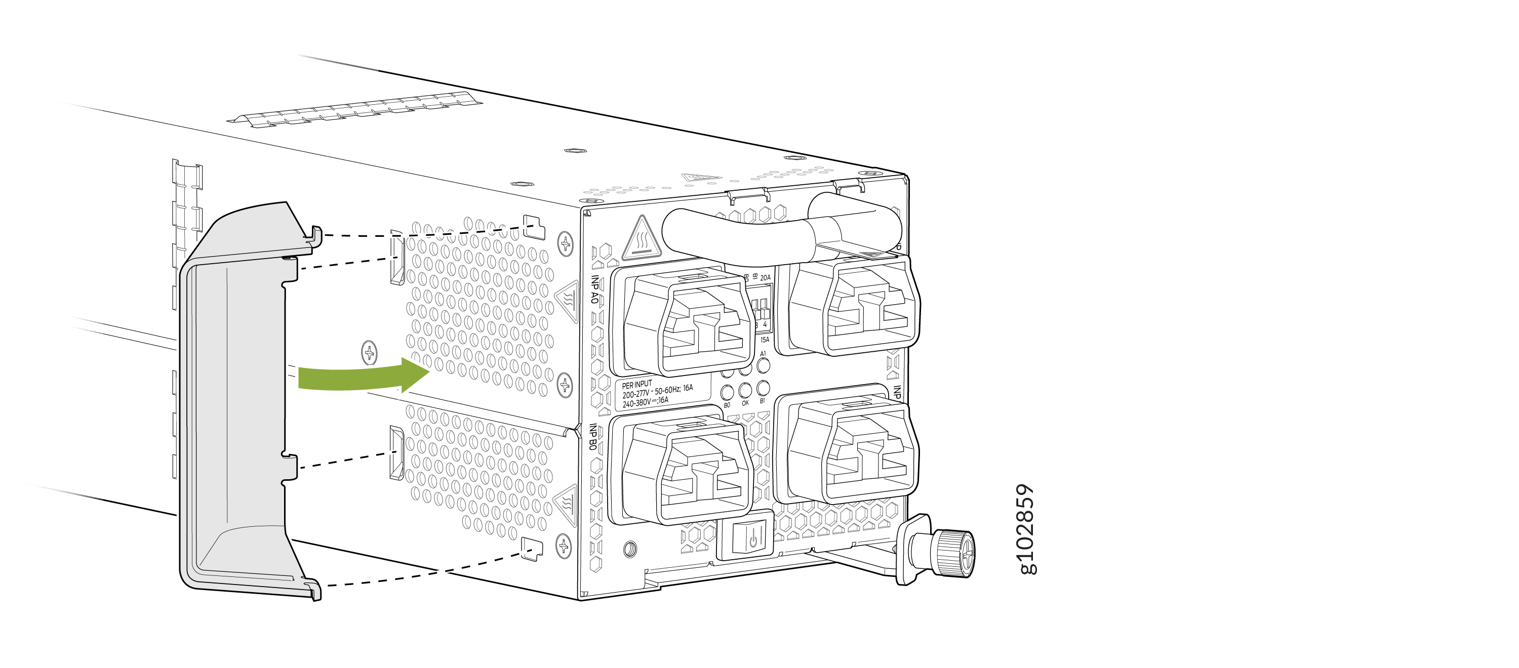
To install a JNP10K-PWR-AC3 power supply in a MX10004:
Remove a JNP10K-PWR-AC3 Power Supply
Before you remove a JNP10K-PWR-AC3 power supply from the chassis:
-
Ensure that you understand how to prevent ESD damage. See Prevention of Electrostatic Discharge Damage.
-
Ensure that you have the following parts and tools available:
-
Heat-protective gloves able to withstand temperatures of 158°F (70°C)
-
Electrostatic discharge (ESD) grounding strap
-
Phillips (+) screwdriver, number 1
-
Replacement power supply or a cover for the power supply slot
-
Protect yourself from severe burns by wearing heat-protective gloves when removing a working JNP10K-PWR-AC3 power supply from the chassis. These power supplies can reach temperatures of 158 °F and 176 °F (70 °C and 80 °C) when the equipment is On.
Before you remove a power supply, ensure that you have power supplies sufficient to power the router left in the chassis. See Power Requirements for MX10004 Components.
Do not leave the power supply slot empty for a long time while the router is operational. Either replace the power supply promptly or install a ABPM or a cover over the empty slot.
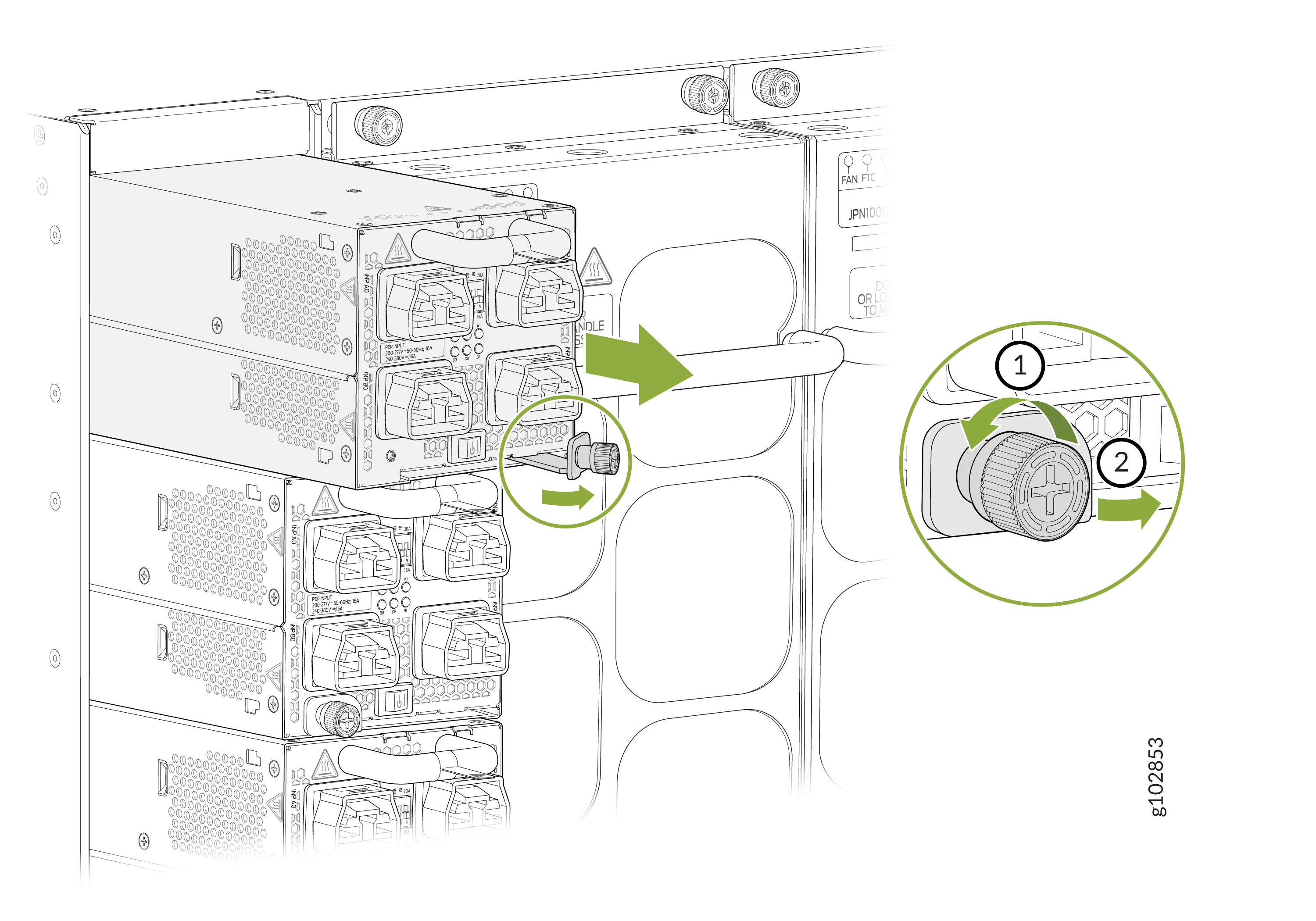
To remove a JNP10K-PWR-AC3 power supply from a MX10004 router:
Install a JNP10K-PWR-AC2 Power Supply
Use the same type of power supply in all slots. Do not mix AC and DC power supplies in a production chassis.
Protect yourself from severe burns by wearing heat-protective gloves when removing a running JNP10K-PWR-AC2 power supply from the chassis. The power supply can reach temperatures of 158 °F through 176 °F (70 °C through 80 °C) when the equipment is On.
Before you install a JNP10K-PWR-AC2 power supply in the chassis:
-
Ensure that you have followed all safety warnings and cautions.
-
Review how to prevent ESD damage. See Prevention of Electrostatic Discharge Damage.
-
If the AC or DC power source outlets have a power switch, set them to the off (O) position.
-
Have a qualified electrician install the HVAC and HVDC connectors and lugs.
-
Ensure that you have the following parts and tools available to install the JNP10K-PWR-AC2 power supply:
-
Electrostatic discharge (ESD) grounding strap
-
Phillips (+) screwdriver, number 1
-
Power cables appropriate for your geographical location (for low-voltage installations) or input amperage (for high-voltage installations). See MX10004 Power Cable Specifications.
-
To install a JNP10K-PWR-AC2 power supply in an MX10004:
Remove a JNP10K-PWR-AC2 Power Supply
Before you remove a JNP10K-PWR-AC2 power supply from the chassis:
-
Review how to prevent ESD damage. See Prevention of Electrostatic Discharge Damage.
-
Ensure that you have the following parts and tools available:
-
Heat-protective gloves able to withstand temperatures of 158° F (70° C)
-
Electrostatic discharge (ESD) grounding strap
-
Phillips (+) screwdriver, number 1
-
Replacement power supply or a cover for the power supply slot
-
Protect yourself from severe burns by wearing heat-protective gloves when removing a working JNP10K-PWR-AC2 power supply from the chassis. These power supplies can reach temperatures of 158 °F through 176 °F (70 °C through 80 °C) when the equipment is On.
Before you remove a power supply, ensure that you have power supplies sufficient to power the router left in the chassis. See Power Requirements for MX10004 Components.
Do not leave the power supply slot empty for a long time while the router is operational. Either replace the power supply promptly or install a cover over the empty slot.
To remove a JNP10K-PWR-AC2 power supply from an MX10004 router:
Install a JNP10K-PWR-DC3 Power Supply
Before you install a JNP10K-PWR-DC3 power supply in the chassis:
-
Ensure that you follow all safety warnings and cautions.
Note:Before performing DC power procedures, ensure that power is removed from the DC circuit. To ensure that all power is off, locate the circuit breaker on the panel board that services the DC circuit, switch the circuit breaker to the off (O) position, and tape the switch handle of the circuit breaker in the off position.
Note:Protect yourself from severe burns by wearing heat-protective gloves when removing a working JNP10K-PWR-DC3 power supply from the chassis. JNP10K-PWR-DC3 power supplies can reach temperatures of 158 °F to 176 °F (70 °C to 80 °C) when the equipment is On.
Note:Before you connect power to the router, a licensed electrician must attach a cable lug to the grounding and power cables that you supply. A cable with an incorrectly attached lug can damage the router (for example, by causing a short circuit).
Note:Use the same type of power supply in all slots. Do not mix AC and DC power supplies in a production chassis.
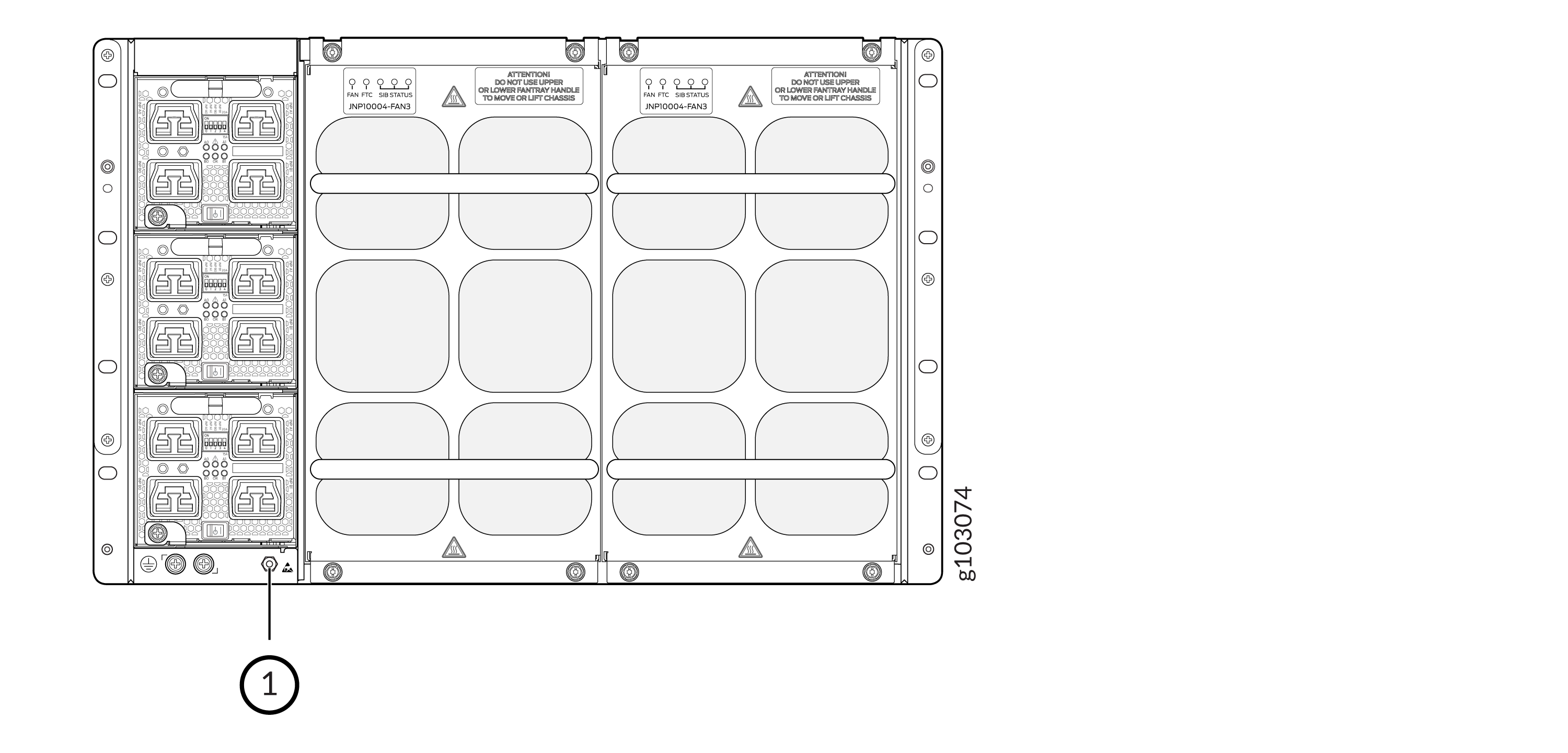
Note:To meet safety and electromagnetic interference (EMI) requirements and to ensure proper operation, you must connect the MX10004 routers to earth ground before you connect them to power. For installations that require a separate grounding conductor to the chassis, use the protective earthing terminal on the router chassis to connect to earth ground. For instructions on connecting an MX10004 router to ground using a separate grounding conductor, see Connect the MX10004 Router to Earth Ground.
Note:The battery returns of the JNP10K-PWR-DC3 power supply must be connected as an isolated DC return (DC-I).
-
Review how to prevent ESD damage. See Prevention of Electrostatic Discharge Damage.
-
Ensure that you have the following parts and tools available before you install a DC power supply:
-
Electrostatic discharge (ESD) grounding strap
-
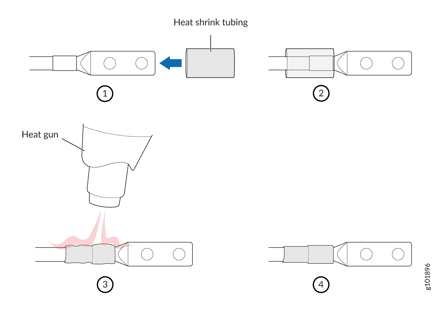
The provided terminal lugs for the JNP10K-PWR-DC3 (Panduit LCD4-14A-L for straight lugs, LCD-4-14AH-L for 45° lugs, or equivalent) and sized for 4 AWG (21.1 mm²) power source cables. We recommend that you install heat-shrink tubing insulation around the crimpled section of the power cables and lugs (see step 9).
-
13/32 in. (10 mm) nut driver or socket wrench
-
Phillips (+) screwdrivers, numbers 1 and 2
-
Multimeter
-
The JNP10K-PWR-DC3 power supply in an MX10004 chassis is a hot-removable and hot-insertable field-replaceable unit (FRU). You can install up to three power supplies in the rear along the left side of the chassis.
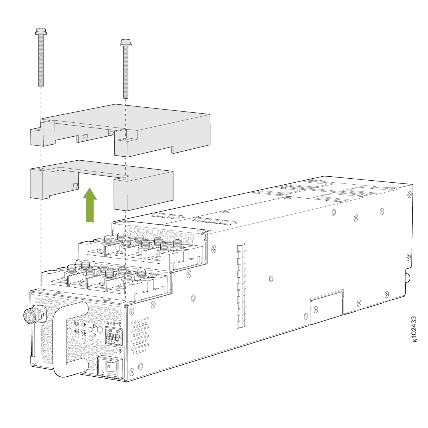
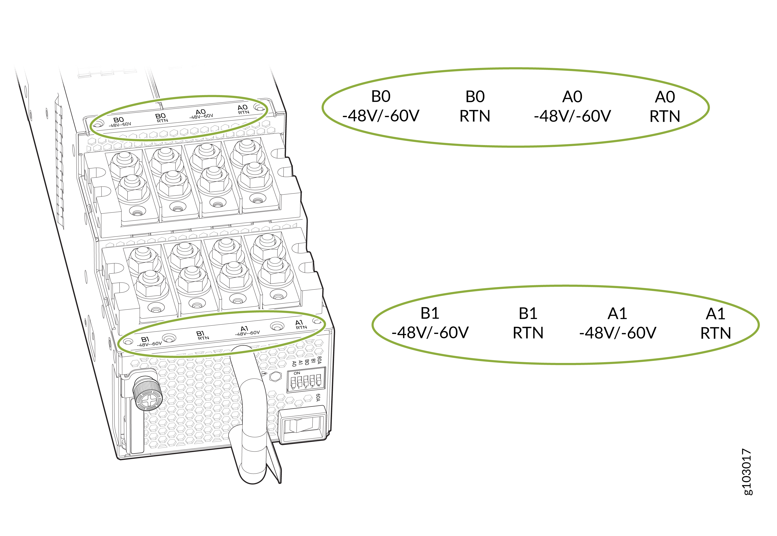
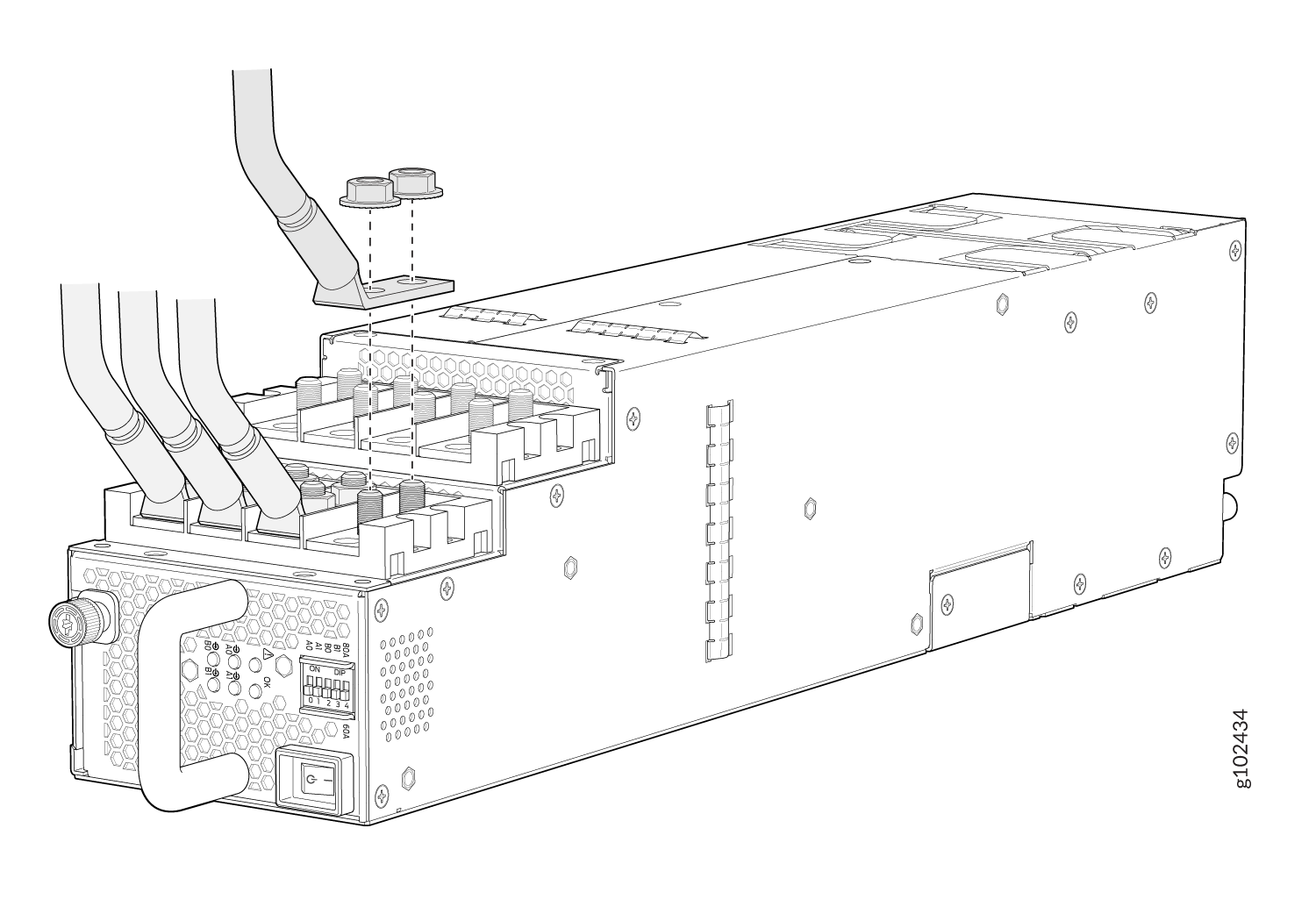
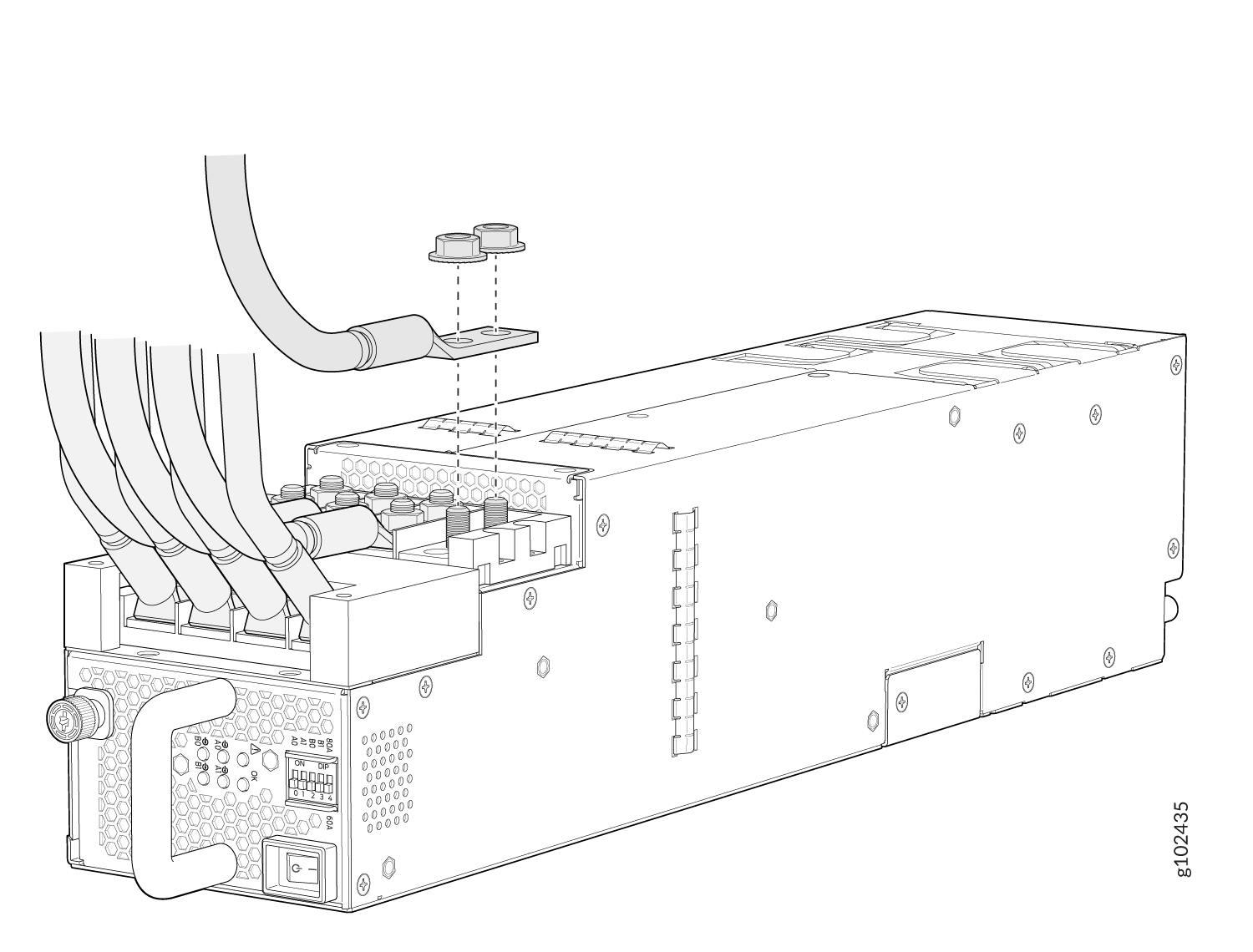
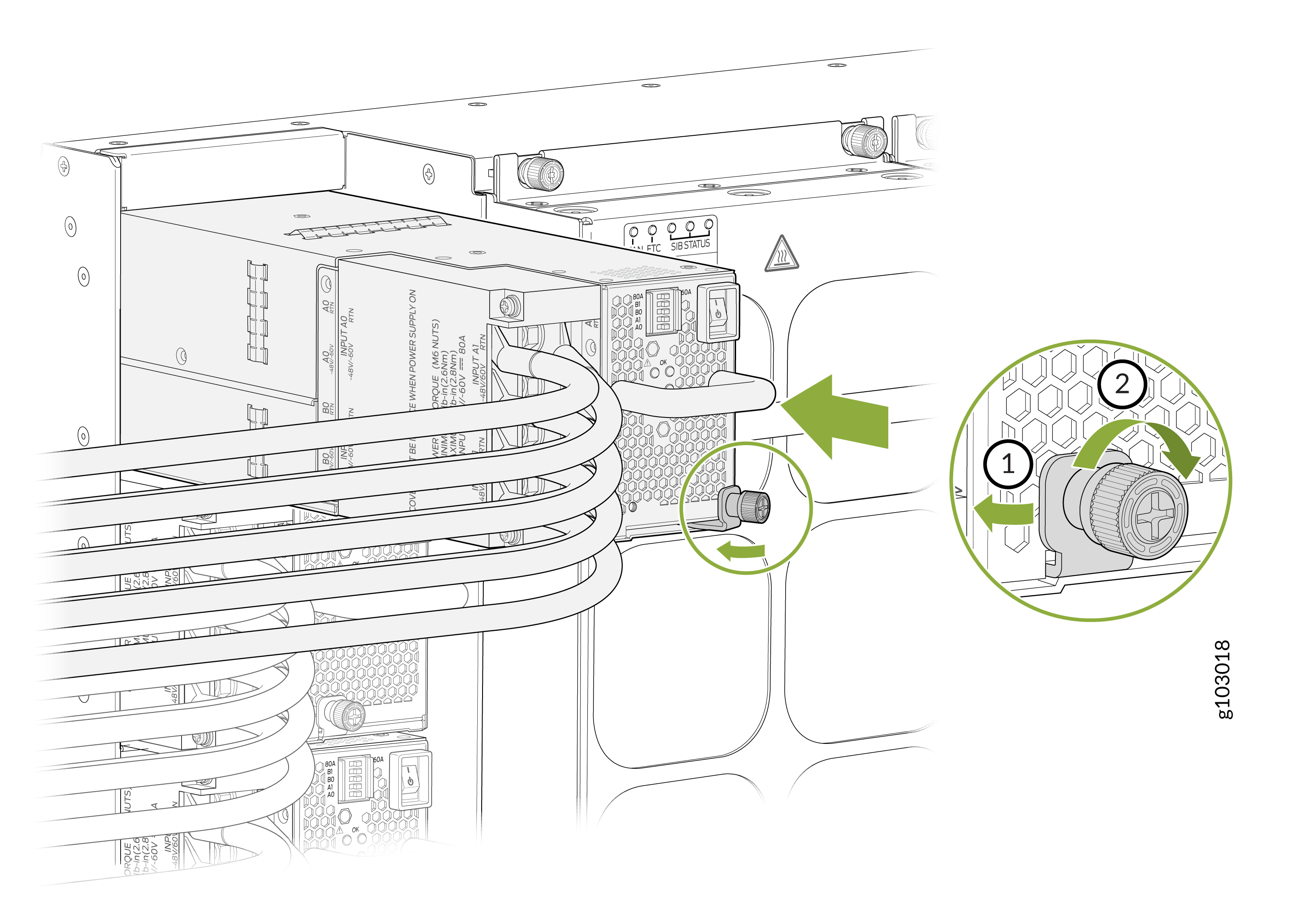
To install a JNP10K-PWR-DC3 power supply in an MX10004:
Remove a JNP10K-PWR-DC3 Power Supply
Before you remove a DC power supply from the router:
-
Review how to prevent ESD damage. See Prevention of Electrostatic Discharge Damage.
-
Ensure that the following parts and tools are available before you remove a JNP10K-PWR-DC3 power supply:
-
Heat-protective gloves that can withstand temperatures from 158° F to 176° F (70° C to 80° C)
-
Electrostatic discharge (ESD) grounding strap
-
Phillips (+) screwdriver, numbers 1 and 2
-
13/32 in. (10 mm) nut driver or socket wrench
-
Replacement power supply or a cover for the power supply slot
-
A working JNP10K-PWR-DC3 power supply can reach temperatures of 158 °F
through 176 °F (70 °C through 80 °C) when the equipment is On. In order to
avoid injury, do not touch a running power supply with your bare
hands.
Before you remove a power supply, ensure that you have power supplies sufficient to power the router left in the chassis. See MX10004 Power Planning and Power Requirements for MX10004 Components.
Do not leave the power supply slot empty for a long time while the router is operational. Either replace the power supply promptly or install an Active Blank Power Module (ABPM) over the empty slot.
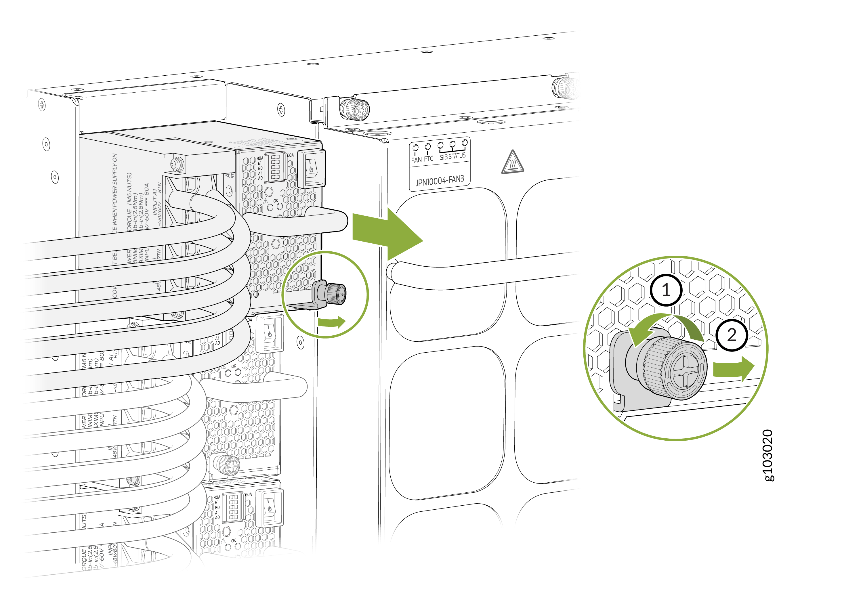
To remove a JNP10K-PWR-DC3 power supply from an MX10004 router:
Install a JNP10K-PWR-DC2 Power Supply
Before you install a JNP10K-PWR-DC2 power supply in the chassis:
-
Ensure that you follow all safety warnings and cautions.
Warning:Before performing DC power procedures, ensure that power is removed from the DC circuit. To ensure that all power is off, locate the circuit breaker on the panel board that services the DC circuit, switch the circuit breaker to the off (O) position, and tape the switch handle of the circuit breaker in the off position.
Warning:Protect yourself from severe burns by wearing heat-protective gloves when removing a working JNP10K-PWR-DC2 power supply from the chassis. JNP10K-PWR-DC2 power supplies can reach temperatures of 158 °F through 176 °F (70 °C through 80 °C) when the equipment is On.
CAUTION:Before you connect power to the router, a licensed electrician must attach a cable lug to the grounding and power cables that you supply. A cable with an incorrectly attached lug can damage the router (for example, by causing a short circuit).
CAUTION:Use the same type of power supply in all slots. Do not mix AC and DC power supplies in a production chassis.
CAUTION:To meet safety and electromagnetic interference (EMI) requirements and to ensure proper operation, you must connect the MX10004 routers to earth ground before you connect them to power. For installations that require a separate grounding conductor to the chassis, use the protective earthing terminal on the router chassis to connect to earth ground. For instructions on connecting an MX10004 router to ground using a separate grounding conductor, see Connect the MX10004 Router to Earth Ground.
Note:The battery returns of the JNP10K-PWR-DC2 power supply must be connected as an isolated DC return (DC-I).
-
Review how to prevent ESD damage. See Prevention of Electrostatic Discharge Damage.
-
Ensure that you have the following parts and tools available to install a DC power supply:
-
Electrostatic discharge (ESD) grounding strap
-
High-current cable assembly CBL-PWR2-BARE (not provided) with the cable lugs (provided) attached and with heat-shrink tubing insulation around the crimped section of the power cables and lugs
The provided terminal lugs for the JNP10K-PWR-DC2 (Panduit LCD4-14A-L, or equivalent) and sized for 4 AWG (21.1 mm2) power source cables
Power source cables as 4 AWG (21.1 mm²) stranded wire that is rated 75° C or per local electrical code
-
13/32 in. (10 mm) nut driver or socket wrench
-
Phillips (+) screwdrivers, numbers 1 and 2
-
Multimeter
-
To install a JNP10K-PWR-DC2 power supply in an MX10004:
Remove a JNP10K-PWR-DC2 Power Supply
Before you remove a DC power supply from the router:
-
Review how to prevent ESD damage. See Prevention of Electrostatic Discharge Damage.
-
Ensure that you have the following parts and tools available to remove a JNP10K-PWR-DC2 power supply:
-
Heat-protective gloves that can withstand temperatures from 158° F to 176° F (70° C to 80° C)
-
Electrostatic discharge (ESD) grounding strap
-
Phillips (+) screwdriver, numbers 1 and 2
-
13/32 in. (10 mm) nut driver or socket wrench
-
Replacement power supply or a cover for the power supply slot
-
A working JNP10K-PWR-DC2 power supply can reach temperatures of 158 °F through 176 °F (70 °C through 80 °C) when the equipment is On. In order to avoid injury, do not touch a running power supply with your bare hands.

Before you remove a power supply, ensure that you have power supplies sufficient to power the router left in the chassis. See MX10004 Power Planning and Power Requirements for MX10004 Components.
Do not leave the power supply slot empty for a long time while the router is operational. Either replace the power supply promptly or install a cover over the empty slot.
To remove a JNP10K-PWR-DC2 power supply from an MX10004 router:
Install a JNP10K-PWR-AC3H Power Supply
Use the same type of power supply in all slots. Do not mix power supply models in a production chassis. The only time you are allowed to have two models concurrently running in a system is when you are in the process of hot-swapping all JNP10K-PWR-AC/JNP10K-PWR-AC2 power supplies with JNP10K-PWR-AC3H power supplies.
Protect yourself from severe burns by wearing heat-protective gloves when removing a running JNP10K-PWR-AC3H power supply from the chassis. The power supply can reach temperatures of 158°F through 176°F (70°C to 80°C) when the equipment is On.
Before you install a JNP10K-PWR-AC3H power supply in the chassis:
-
Ensure that you have followed all safety warnings and cautions.
-
Ensure that you understand how to prevent ESD damage. See Prevention of Electrostatic Discharge Damage.
-
If the AC power source outlets have a power switch, set them to the off (O) position. Ensure that you have the following parts and tools available to install the JNP10K-PWR-AC3H power supply:
-
Electrostatic discharge (ESD) grounding strap
-
Phillips (+) screwdriver, number 1
-
Power cables appropriate for your geographical location (for low-voltage installations) or input amperage (for high-voltage installations). See MX10004 Power Cable Specifications.
-
To install a JNP10K-PWR-AC3H power supply in a MX10004:
Remove a JNP10K-PWR-AC3H Power Supply
Before you remove a JNP10K-PWR-AC3H power supply from the chassis:
-
Ensure that you understand how to prevent ESD damage. See Prevention of Electrostatic Discharge Damage.
-
Ensure that you have the following parts and tools available:
-
Heat-protective gloves able to withstand temperatures of 158°F (70°C)
-
Electrostatic discharge (ESD) grounding strap
-
Phillips (+) screwdriver, number 1
-
Replacement power supply or a cover for the power supply slot
-
Protect yourself from severe burns by wearing heat-protective gloves when removing a working JNP10K-PWR-AC3H power supply from the chassis. The power supply can reach temperatures of 158°F through 176°F (70°C to 80°C) when the equipment is On.
Before you remove a power supply, ensure that you have power supplies sufficient to power the router left in the chassis. See Power Requirements for MX10004 Components.
Do not leave the power supply slot empty for a long time while the router is operational. Either replace the power supply promptly or install a ABPM or a cover over the empty slot.
To remove a JNP10K-PWR-AC3H power supply from a MX10004 router:

