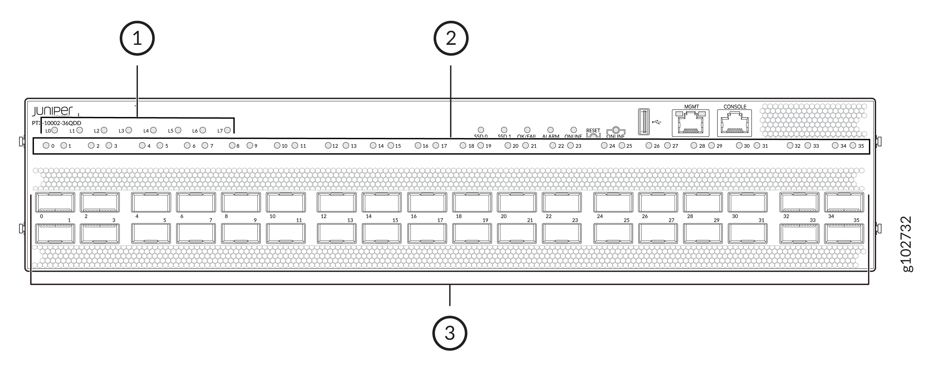
PTX10002-36QDD Port Panel
The port panel in a PTX10002-36QDD router has 36 high-density ports. The panel also has LEDs that indicate the speed and status of the ports.

1 — Lane LEDs | 3 — Network ports |
2 — Port LEDs |
The router operates in the normal power mode when 3000-W power supply units (PSUs) are installed in the router. The router operates in the power-optimized mode when 2200-W PSUs are installed in it. The ports support 800 Gbps speed in the normal power mode and provides a throughput of 28.8 Tbps. The ports support 400 Gbps speed in the power-optimized mode and provides a throughput of 14.4 Tbps. You can see the power mode by using the show chassis power command.
The links on the ports come up at 400 Gbps speed by default, irrespective of the power mode. You can change the port speed to 800 Gbps by using the speed command.
When the router is operating in the power-optimized mode, the ports support SFP+ by using QSA adapter, QSFP+, QSFP28, QSFP56-DD, or high-power 400G-ZR transceivers. When the router is operating in the normal power mode, the ports support 800 Gbps transceivers additionally.
The ports support breakout cables and active optical cables.
You can channelize the ports by using the number-of-sub-ports (interface) command to operate in the following speeds:
-
2x400 Gbps
-
8x100 Gbps
-
4x100 Gbps
-
3x100 Gbps
-
2x100 Gbps
-
2x50 Gbps
-
4x25 Gbps
-
4x10 Gbps
You can channelize the ports to operate in 2x400 Gbps or 8x100 Gbps speed when the router is operating in the normal power mode.
Table 1 describes the port LEDs. The lane LEDs work in conjunction with the port LEDs. Table 2 describes the lane LEDs. Table 3 describes the lane LEDs that indicate the lane status in the different channelization modes.
When a lane is down, the lane LED for that lane and the LED on the port that has that lane blink in red color. If there are more than one port that have lanes that are down, the port LEDs on those ports blink in red color for 30 seconds, one after the other.
|
State |
Color |
Pattern |
Description |
|---|---|---|---|
|
On |
Green |
On steadily |
A link is established and all the channels are up. |
|
On |
Green |
Blinking |
The lane LED is indicating the fault in a port that is not receiving any signal. |
|
On |
Green |
Blipping |
The beacon function is enabled on the port. |
|
On |
Red |
On steadily |
The transceiver installed in the port has a failure. |
|
On |
Red |
Blinking |
The port is down; there is a failure in the transceiver hardware. |
|
On |
Amber |
On steadily |
The port has a fault (other than failure of the transceiver installed in it and the port not receiving any signal) and is not functioning normally. |
|
On |
Amber |
Blinking |
The port is down; there is a failure other than in the transceiver hardware or the port is not receiving any signal. |
|
Off |
— |
— |
The port is not receiving any signal. |
|
State |
Color |
Pattern |
Description |
|---|---|---|---|
|
On |
Green |
On steadily |
The lane is up. |
|
On |
Amber |
On steadily |
The lane is disabled. |
|
Off |
— |
— |
The lane is not receiving any signal. |
|
Channelization Mode |
LEDs that Indicate the Lane Status |
|---|---|
|
2x400 Gbps |
L0 and L1 |
|
8x100 Gbps |
L0 through L7 |
|
4x100 Gbps |
L0 through L3 |
|
3x100 Gbps |
L0 through L2 |
|
2x100 Gbps |
L0 and L1 |
|
2x50 Gbps |
L0 and L1 |
|
4x25 Gbps |
L0 through L3 |
|
4x10 Gbps |
L0 through L3 |
