ON THIS PAGE
Fast Track to Rack Installation and Power
This procedure guides you through the simplest steps for the most common installation to mount your PTX10003 router in a rack and connect it to power.
Mount the Router
You can mount a PTX10003 router on a four-post rack or cabinet by using the rack mount kit shipped with the router by default. We’ll walk you through the steps to mount a router and connect it to power.
The weight of a fully-loaded PTX10003-160C is approximately 110 lb (50 kg). The weight of a fully-loaded PTX10003-160C is approximately 88 lb (40 kg).
You must install the router in a restricted-access location and ensure that the chassis is always grounded properly.
Before you install, review the following:
Mount the Router
The mounting rails and mounting blades are preattached to the PTX10003. To mount the chassis in a 19-in (48.26 cm) four-post rack, remove one screw to release the sliding rail and then attach the mounting blades to the rack. The sliding mounting rails enable the PTX10003 to be mounted flush with the rack and still be adjustable for racks with different depths. The minimum distance the front and rear rack rails can be spaced apart is 26 in. (66.04 cm) front to back. The maximum distance the front and rear rack rails can be spaced apart is 36 in. (91.4 cm) front to back.
To mount the router:
Wrap and fasten one end of the ESD grounding strap around your bare wrist, and connect the other end to a site ESD point.
Using a Phillips screwdriver, remove the screw on each side of the chassis that holds the mounting
rails to the chassis.Slide the mounting rail out of the mounting blades.
Figure 1: Removing the Slide Rail Screw from PTX10003-80C Figure 2: Removing the Slide Rail Screw from PTX10003-160C
Use a mechanical lift to position the PTX10003 in the rack so that the front brackets on the front mounting rails are aligned with the rack holes.
Continue to support the PTX10003 while sliding the rear mounting blades into the channel of the side-mounting rails.
Figure 3: Secure the Side Rails to the PTX10003-80C Chassis Figure 4: Secure the Side Rails to the PTX10003-160C
Ensure that the PTX10003 chassis is level by verifying that all the screws on the front of the rack are aligned with the screws at the back of the rack.
Figure 5: PTX10003-80C Secured in a Rack Figure 6: PTX10003-160C Secured in Rack
Connect to Power
To connect the router to AC power:
Install the Power Supplies
To install the power supplies:
If the power supply slot has a cover on it, insert your thumb and forefinger into the finger holes, squeeze, and pull the cover out of the slot. Save the cover for later use.
Taking care not to touch power supply components, pins, leads, or solder connections, remove the power supply from its bag.
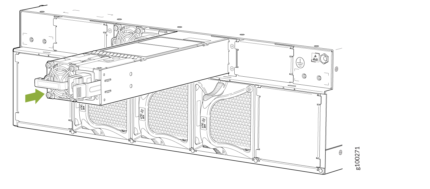
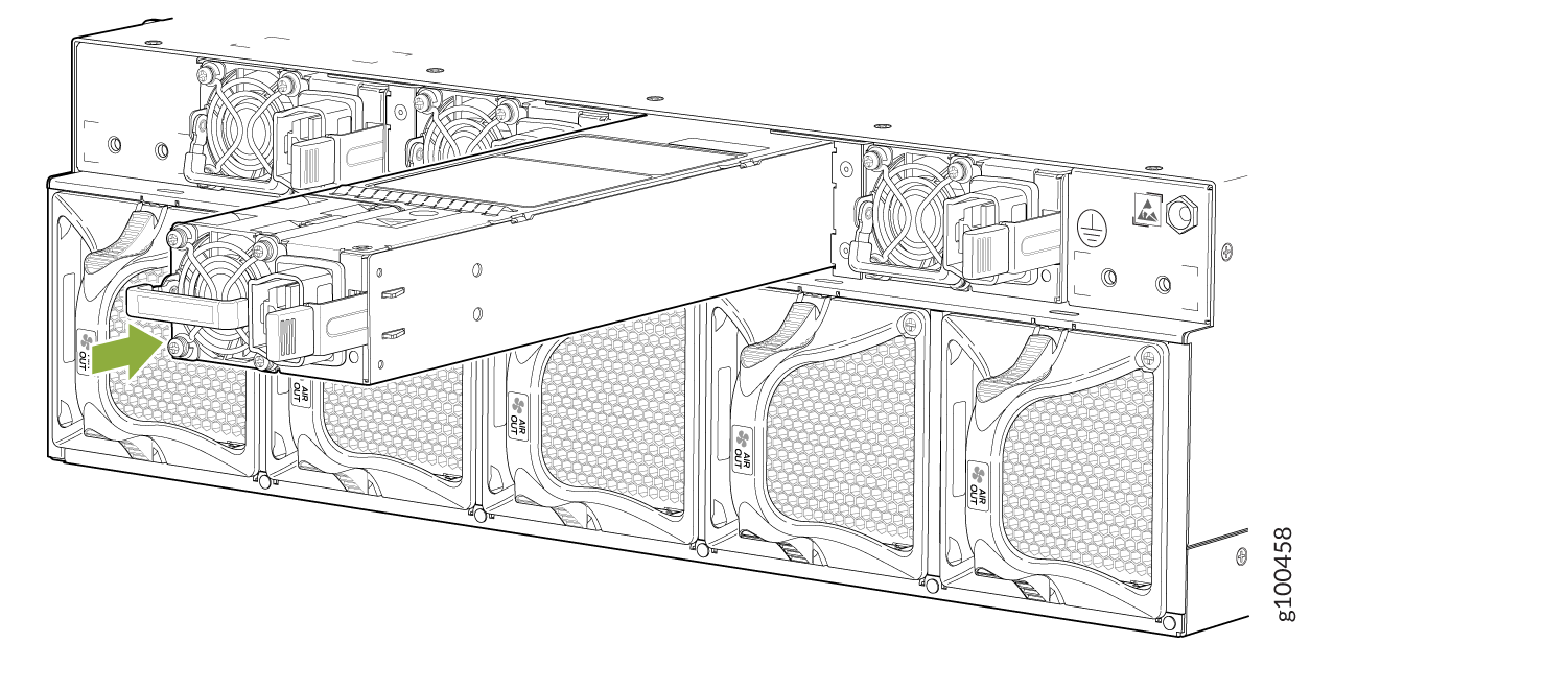
Using both hands, place the power supply in the power supply slot on the field replaceable units (FRU) panel of the PTX10003 and slide it in until it is fully seated and the ejector lever slides into place.
Figure 7: Installing an AC/HVDC Power Supply in a PTX10003-80C Figure 8: Installing an AC/HVDC Power Supply in a PTX10003-160C
Ground the Router
To ground the router:
Verify that a licensed electrician has attached the protective earthing terminal lug (provided in the accessory kit) to the grounding cable.
Connect the other end of the grounding cable to a proper earth ground, such as the rack in which the router is installed.
Remove the two screws on the earthing terminal by using a screwdriver. Save the screws.
Figure 9: Chassis Grounding Point on PTX10003-80C Figure 10: Chassis Grounding Point on PTX10003-160C
Place the chassis grounding lug and cable over the screw holes.
Place the two screws over the grounding lug and grounding cable.
Tighten the two screws by using a screwdriver.
Dress the grounding cable and ensure that it does not touch or block access to other device components and that it does not drape where people can trip over it.
Connect the Power Cable and Power On the Router
To connect the power cable and power on the router:
Locate the power cord or cords shipped with the router; the cords have plugs appropriate for your geographical location.
Warning:Ensure that the power cords do not block access to router components or drape where people can trip on them.
Connect each power supply to the power sources. Insert the coupler end of the power cord into the AC power cord inlet on the AC power supply faceplate.
Figure 11: Connect an AC Power Cord to the PTX10003-80C Figure 12: Connect an AC Power Cord to the PTX10003-160C
If the AC power source outlet has a power switch, set it to the off (O) position.
Note:The router powers on as soon as power is provided to the power supply. There is no power switch on the router.
Insert the power cord plug into an AC power source outlet.
If the AC power source outlet has a power switch, set it to the on (|) position.
Verify that the status LEDs on each power supply are lit green.
If the status LED is lit amber, remove power from the power supply, and replace the power supply (see Maintaining the PTX10003 Power Supplies). Do not remove the power supply until you have a replacement power supply ready.
