Maintain the PTX10016 Transceivers and Fiber-Optic Cables
The transceivers for the PTX10016 router are hot-removable and hot-insertable field-replaceable units (FRUs). You can remove and replace them without powering off the device or disrupting device functions.
To understand how to install or remove a transceiver in the PTX10016 router, read the following sections:
Install a Transceiver in the PTX10016 Router
Before you install a transceiver in a PTX10016 line card or RCB, ensure that you have taken the necessary precautions for safe handling of lasers (see Laser and LED Safety Guidelines and Warnings).
Ensure that you have a rubber safety cap available to cover the transceiver and an Electrostatic discharge (ESD) grounding strap (provided in the accessory kit).
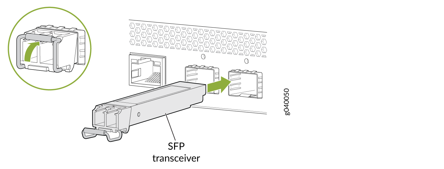
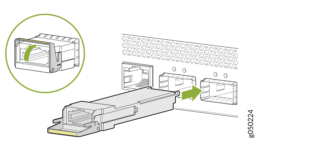
To install a transceiver in the PTX10016 line card or RCB:
To avoid damaging the transceiver by electrostatic discharge (ESD), do not touch the connector pins at the end of the transceiver.
-
Wrap and fasten one end of the ESD wrist strap around your bare wrist, and
connect the other end of the strap to one of the ESD points on the chassis.
An ESD point is located above the status LED panel on the front of the
PTX10016 chassis (see Figure 1).
Figure 1: ESD Point on the Front of the PTX10016 Chassis
 1—
1—ESD point
Remove a Transceiver from the PTX10016 Router
Before you remove a transceiver from the PTX10016 line card or RCB, ensure that you have taken the necessary precautions for safe handling of lasers (see Laser and LED Safety Guidelines and Warnings).
Ensure that you have the following parts and tools available:
-
An antistatic bag or an antistatic mat
-
Rubber safety caps to cover the transceiver and fiber-optic cable connector
-
Dust cover to cover the port
-
An Electrostatic discharge (ESD) grounding strap (provided in the accessory kit)
To remove a transceiver from the PTX10016 line card or RCB:
-
Wrap and fasten one end of the ESD wrist strap around your bare wrist, and
connect the other end of the strap to one of the ESD points on the chassis.
An ESD point is located above the status LED panel on the front of the
PTX10016 chassis (see Figure 4).
Figure 4: ESD Point on the Front of the PTX10016 Chassis
1—
ESD point
Connect a Fiber-Optic Cable to a Transceiver Installed in the PTX10016 Router
Before you connect a fiber-optic cable to an optical transceiver installed in the PTX10016 router, ensure that you have taken the necessary precautions for safe handling of lasers (see Laser and LED Safety Guidelines and Warnings).
Ensure that you have an Electrostatic discharge (ESD) grounding strap (provided in the accessory kit).
To connect a fiber-optic cable to an optical transceiver installed in the PTX10016 router:
Do not look directly into a fiber-optic transceiver or into the ends of fiber-optic cables. Fiber-optic transceivers and fiber-optic cables connected to transceivers emit laser light that can damage your eyes.
Do not stare into the laser beam or view it directly with optical instruments even if the interface has been disabled.
-
Wrap and fasten one end of the ESD wrist strap around your bare wrist, and
connect the other end of the strap to one of the ESD points on the chassis.
An ESD point is located above the status LED panel on the front of the
PTX10016 chassis (see Figure 5).
Figure 5: ESD Point on the Front of the PTX10016 Chassis
1—
ESD point
Disconnect a Fiber-Optic Cable from a Transceiver Installed in the PTX10016 Router
Before you disconnect a fiber-optic cable from an optical transceiver installed in the PTX10016 router, ensure that you have taken the necessary precautions for safe handling of lasers (see Laser and LED Safety Guidelines and Warnings).
Ensure that you have the following parts and tools available:
-
Rubber safety cap to cover the transceiver
-
Rubber safety cap to cover the fiber-optic cable connector
-
An Electrostatic discharge (ESD) grounding strap (provided in the accessory kit)
To disconnect a fiber-optic cable from an optical transceiver installed in the PTX10016 router:
-
Wrap and fasten one end of the ESD wrist strap around your bare wrist, and
connect the other end of the strap to one of the ESD points on the chassis.
An ESD point is located above the status LED panel on the front of the
PTX10016 chassis (see Figure 6).
Figure 6: ESD Point on the Front of the PTX10016 Chassis
1—
ESD point
Maintain the Fiber-Optic Cable for the PTX10016 Router
To maintain fiber-optic cables in the PTX10016 router:
When you unplug a fiber-optic cable from a transceiver, place rubber safety caps over the transceiver and on the end of the cable.
Anchor fiber-optic cable to avoid stress on the connectors. When attaching a fiber-optic cable to a transceiver, be sure to secure the fiber-optic cable so that it does not support its own weight as it hangs to the floor. Never let a fiber-optic cable hang free from the connector.
Do not bend fiber-optic cables beyond their minimum bend radius. Bending the cables beyond their minimum bend radius can damage the cables and cause problems that are difficult to diagnose.
Frequent plugging and unplugging of fiber-optic cables in and out of optical instruments can damage the instruments, which are expensive to repair. Attach a short fiber extension to the optical equipment. Any wear and tear due to frequent plugging and unplugging is then absorbed by the short fiber extension, which is easier and less expensive to replace than the instruments.
Keep fiber-optic cable connections clean. Microdeposits of oil and dust in the canal of the transceiver or cable connector can cause loss of light, reduction in signal power, and possibly intermittent problems with the optical connection.
To clean the transceiver canal, use an appropriate fiber-cleaning device such as RIFOCS Fiber Optic Adaptor Cleaning Wands (part number 946). Follow the directions in the cleaning kit you use.
After cleaning the transceiver, make sure that the connector tip of the fiber-optic cable is clean. Use only an approved alcohol-free fiber-optic cable cleaning kit such as the Cletop-S® Fiber Cleaner. Follow the directions in the cleaning kit you use.