PTX5000 Chassis
PTX5000 Chassis Description
The PTX5000 chassis is a rigid sheet metal structure that houses all the other hardware components (see Figure 1 and Figure 2). The chassis measures 62.5 in. (158.8 cm) high, 33.1 in. (84.1 cm) deep, and 17.5 in. (44.5 cm) wide. The chassis can be installed into many types of racks or cabinets.
The chassis includes the following features (see Figure 1 and Figure 2):
Front-mounting flanges for mounting in a four-post rack or cabinet.
Center-mounting metal brackets for center-mounting in an open-frame rack.
Handles on each side to facilitate positioning the PTX5000 in the rack. Do not use the handles to lift the PTX5000.
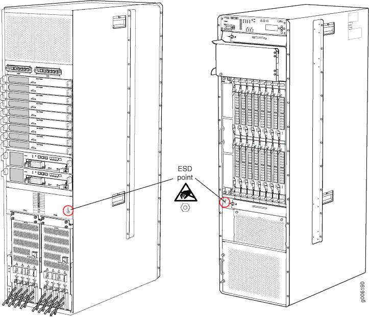
Two electrostatic discharge (ESD) points (banana plug receptacles), one front and one rear (see Figure 3).
CAUTION:Before removing or installing components, attach an ESD strap to an ESD point, and place the other end of the strap around your bare wrist. Failure to use an ESD strap could result in damage to the hardware components.
Warning:The PTX5000 must be connected to earth ground during normal operation.
Figure 1: Front View of the PTX5000 Chassis 1—
1—Front-mounting flange
6—FPCs and PICs
2—Craft interface
7—ESD point
3—Upper horizontal fan tray
8—Lower horizontal fan tray
4—Cable management system
9—Horizontal air filter
5—Vertical fan tray and vertical air filter
10—Power supply module door and power supply modules air filter
Figure 2: Rear View of the PTX5000 Chassis 1—
1—Center-mounting bracket
6—Control Board CB1 and Routing Engine RE1
2—Air exhaust
7—ESD points
3—Centralized Clock Generators (CCGs)
8—Power distribution units (PDUs)
4—Switch Interface Boards (SIBs)
9—Chassis grounding points
5—Control Board CB0 and Routing Engine RE0

See Also
PTX5000 Midplane Description
The midplane is located in the center of the chassis and forms the rear of the Flexible PIC Concentrator (FPC) card cage. The FPCs install into the midplane from the front of the chassis; and the Switch Interface Boards (SIBs), Routing Engines, Control Boards, Centralized Clock Generators (CCGs), and power distribution units (PDUs) install into the midplane from the rear of the chassis. The cooling system components also connect to the midplane.
The midplane performs the following major functions:
Data path—Data packets are transferred across the midplane from the Packet Forwarding Engine on the originating FPC to the SIBs, and from the SIBs across the midplane to the Packet Forwarding Engine on the destination FPC.
Power distribution—The power distribution units are connected to the midplane, which distributes power to all the PTX5000 components.
Signal path—The midplane provides the signal path to the FPCs, SIBs, Routing Engines, Control Boards, and other system components for monitoring and control of the system.
The PTX5000 supports two midplanes. First supported in
Junos 14.1, the PTX5000BASE2 model is a chassis with an enhanced midplane
that requires high-capacity PDUs and PSMs. The enhanced midplane is
identified as Midplane-8SeP in the output from the show chassis hardware operational-mode CLI command.
If you are installing FPC3-PTX-U3, it must be installed in the PTX5000BASE2 model.
PTX5000 Cable Management System
The front cable management system for the PTX5000 consists of channels above the FPCs. The cable management system organizes, supports, and provides strain relief for the PIC cables. The PIC cables are routed toward the top into the cable management system, keeping the cables organized and securely in place. All the cables from one FPC are routed to one channel. The cables are routed from the cable management system to the left side of the PTX5000. The front cable management system adds 3.8 in. (9.7 cm) to the depth of the chassis.
You can install a rear cable management system with the High Capacity DC power supply. The rear cable management system adds 5.5 in. (14 cm) to the depth of the chassis. See Installing the PTX5000 Cable Management System for a High Capacity DC PDU for details.
We recommend that you use the cable management system to maintain the cable bend radius.
See Also
PTX5000 Craft Interface Description
The craft interface allows you to view status and troubleshooting information at a glance and to perform many system control functions. It is hot-insertable and hot-removable. The craft interface is located at the upper front of the PTX5000.
Craft Interface Front Panel
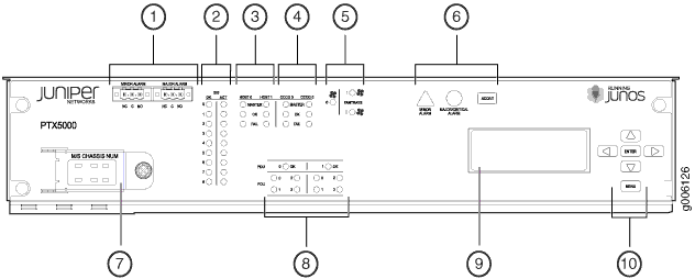
Figure 4 shows the craft interface.

1 — Alarm relay contacts | 6 — Alarm LEDs and ACO/LT button |
2 — SIB LEDs | 7 — M/S CHASSIS NUM configuration switches |
3 — Host Subsystem LEDs | 8 — Power system LEDs |
4 — CCG LEDs | 9 — LCD |
5 — Fan tray LEDs | 10 — LCD navigation buttons |
The front panel of the craft interface contains:
A four-line LCD display, along with six navigation buttons. The LCD display operates in Idle mode or alarm mode.
Alarm relay contacts.
Two configuration switches:
The M/S configuration switch must be set to S.
The CHASSIS ID configuration switch must always be set to 0.
Note:The CHASSIS ID configuration switch is set to 0 by default.
LEDs
Yellow Minor Alarm LED, Red Major Critical Alarm LED, and alarm cutoff/lamp test ACO/LT button
Host Subsystem Master, OK, and FAIL LEDs
SIB OK and ACT LEDs
Fan tray LEDs
PDU LEDs
PSM LEDs
Craft Interface LCD
A four-line LCD is located in the craft interface, along with six navigation buttons. The LCD operates in two modes:
LCD idle mode
LCD alarm mode
Idle Mode
During normal operation, the LCD operates in idle mode and reports current status information, as shown in Figure 5.

The lines in the display report the following information:
First line—Router name.
Second line—Length of time the PTX5000 has been running, reported in the following form:
Up days + hours:minutes
Third and fourth lines—Status messages, which rotate at 2-second intervals. Some conditions, such as removal or insertion of a system component, can interrupt the messages.
To add a message that alternates every 2 seconds with the default
status messages, use the set chassis display message command.
Alarm Mode
When a red or yellow alarm occurs, the LCD switches to alarm mode and reports the alarm condition, as shown in Figure 6.

The lines in the display report the following information:
First line—Router name.
Second line—Number of active alarms.
Third and fourth lines—Individual alarm messages, with the most severe condition shown first. The prefix on each line indicates whether the alarm is a red (
R) or yellow (Y) alarm.
LCD Navigation Buttons
The LCD display has the following navigation buttons:
Menu button
Enter button
Four arrow buttons for scrolling up or down, and left or right
PTX5000 Craft Interface LEDs
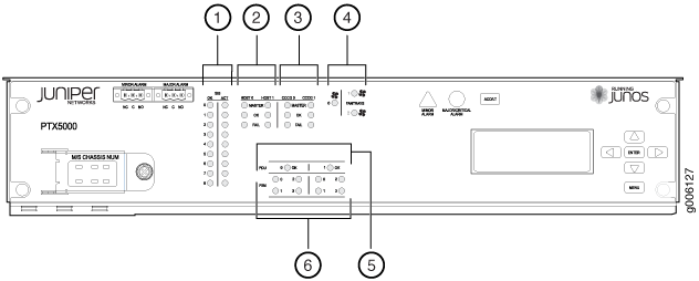
Figure 7 shows the craft interface LEDs.

1 — SIB LEDs | 4 — Fan tray LEDs |
2 — Host subsystem LEDs | 5 — Power distribution unit LEDs |
3 — CCG LEDs | 6 — Power supply module LEDs |
- Craft Interface Alarm LEDs
- Craft Interface SIB LEDs
- Craft Interface Host Subsystem LEDs
- CCG LEDs
- Fan Trays LEDs
- Power Distribution Unit LEDs
- Power Supply Modules LEDs
Craft Interface Alarm LEDs
Two large alarm LEDs are located on the craft interface. Both LEDs can be lit simultaneously.
The circular red LED lights to indicate a critical condition that can result in a system shutdown.
The triangular yellow LED lights to indicate a less severe condition that requires monitoring or maintenance.
The LCD display on the craft interface reports the cause of the alarm. A condition that causes an alarm LED to light also activates the corresponding alarm relay contact on the craft interface.
Table 1 describes the alarm LEDs.
Shape |
Color |
State |
Description |
|---|---|---|---|
 |
Red |
On steadily |
Critical alarm LED—Indicates a critical condition that can cause the PTX5000 to stop functioning. Possible causes include component removal, failure, or overheating. |
 |
Yellow |
On steadily |
Warning alarm LED—Indicates a serious but nonfatal error condition, such as a maintenance alert or a significant increase in component temperature. |
Craft Interface SIB LEDs
The left side of the craft interface has two LEDs for each SIB, which indicate the status of that SIB. The corresponding SIB slots are labeled 0 through 8. Table 2 describes the functions of the SIB LEDs.
Label |
Color |
State |
Description |
|---|---|---|---|
OK |
Green |
On steadily |
SIB is functioning normally. |
Red |
On steadily |
SIB has failed. |
|
– |
Off |
SIB is offline or absent. |
|
ACT |
Green |
On steadily |
SIB is in active mode and actively passing traffic. |
– |
Off |
SIB is either offline or not actively passing traffic. |
Craft Interface Host Subsystem LEDs
Each host subsystem has three LEDs—labeled MASTER, OK, and FAIL—located to the right of the SIB LEDs on the craft interface, that indicate the status of the host subsystem. The LEDs listed under HOST0 show the status of the Routing Engine in slot RE0 and the CB in slot CB0. The LEDs listed under HOST1 show the status of the Routing Engine in slot RE1 and the CB in slot CB1. Table 3 describes the functions of the host subsystem LEDs.
Label |
Color |
State |
Description |
|---|---|---|---|
MASTER |
Green |
On steadily |
Host subsystem is functioning as the primary. |
– |
Off |
Host subsystem is offline or functioning as the backup. |
|
OK |
Green |
On steadily |
Host subsystem is online and is functioning normally. |
– |
Off |
Host subsystem is offline or absent. |
|
FAIL |
Red |
On steadily |
Host subsystem has failed. |
– |
Off |
No failure has been detected. |
CCG LEDs
Each Centralized Clock Generator (CCG) has three LEDs—labeled MASTER, OK, and FAIL—located to the right of the host subsystem LEDs on the craft interface that indicate the status of the CCGs. The LEDs labeled CCG0 show the status of the CCG in slot CCG0. The LEDs labeled CCG1 show the status of the CCG in slot CCG1. Table 4 describes the functions of the CCG LEDs.
Label |
Color |
State |
Description |
|---|---|---|---|
MASTER |
Green |
On steadily |
CCG is functioning as the primary. |
– |
Off |
CCG is offline or functioning as the backup. |
|
OK |
Green |
On steadily |
CCG is online and is functioning normally. |
– |
Off |
CCG is offline or absent. |
|
FAIL |
Red |
On steadily |
CCG has failed. |
– |
Off |
No failure has been detected. |
Fan Trays LEDs
One status LED for each fan tray is located to the right of the host subsystem LEDs on the craft interface. The three fan tray status LEDs are labeled 0 through 2.
Color |
State |
Description |
|---|---|---|
Green |
On steadily |
The fan tray is functioning normally. |
Red |
On steadily |
The fan tray has failed. |
– |
Off |
The fan tray is offline or absent. |
Power Distribution Unit LEDs
One OK LED for each power distribution unit is located on the craft interface below the host subsytem LEDs. The two LEDs are labeled 0 and 1.
Colour |
State |
Description |
|---|---|---|
Green |
On steadily |
PDU is functioning normally. |
Red |
On steadily |
PDU has failed. |
Off |
— |
PDU might be starting up or not receiving any input voltage. The circuit breakers might be off. |
Power Supply Modules LEDs
A status LED for each power supply module is located on the craft interface below the PDU LEDs. The four PSM status LEDs are labeled 0 through 3.
The existing PDUs support four PSMs whereas high capacity PDUs support eight PSMs.
PDU Type |
No of PSMs per PDU |
Mapping of the PSM LEDs on the Craft Interface and the PSMs |
|||
|---|---|---|---|---|---|
PSM 0 LED |
PSM 1 LED |
PSM 2 LED |
PSM 3 LED |
||
Existing PDUs: PDU-PTX-DC-120 PDU-PTX-DC-60 PDU-PTX-AC-W PDU-PTX-AC-D |
4 |
PSM 0 |
PSM 1 |
PSM 2 |
PSM 3 |
High Capacity PDU: PDU2-PTX-DC |
8 |
PSMs 0 and 4 |
PSMs 1 and 5 |
PSMs 2 and 6 |
PSMs 3 and 7 |
Color |
State |
Description for normal capacity PDU/PSMs |
Description for high capacity PDU/PSMs |
|---|---|---|---|
Green |
On steadily |
The PSM is functioning normally. |
All the PSMs are working. |
Red |
On steadily |
The PSM has failed. |
At least one PSM is not working. Additional status is available on the LCD, CLI, and PSM LEDs on the PSM. |
– |
Off |
The PSM is offline or absent. |
The PSMs are offline or absent. |
PTX5000 Centralized Clock Generator Description
CCG Slots
The Centralized Clock Generators (CCGs) are installed into the upper rear of the chassis in the slots labeled CCG0 and CCG1. One CCG is shipped as part of the standard PTX5000 configuration, but up to two CCGs can be installed to provide redundancy.
A nonredundant CCG is hot-pluggable. For redundant CCGs, the primary CCG is hot-pluggable. The backup CCG is hot-removable and hot-insertable if the primary CCG is functioning. Removing the backup CCG does not affect the functioning of the PTX5000. Taking the primary CCG offline might result in a brief loss of the clock lock while the backup CCG becomes the primary.
CCG Function
CCGs provide a 19.44-MHz Stratum 3E clock signal for the Ethernet network interfaces on the PTX5000.
CCG Components
Each CCG (see Figure 8) consists of the following components:
19.44-MHz Stratum 3E clock.
Field-programmable gate array (FPGA) that performs multiplexing of clock sources.

1 — Three LEDs—OK, FAIL, and MASTER—that display the status of the CCG. | 3 — Two RJ-48 connectors labeled BITS A and BITS B for BITS external clock inputs, 1.5444 MHz or 2.048 MHz. Two LEDs for each BITS connector—FAULT and LINK—that display the status of the BITS ports. |
2 — ONLINE/OFFLINE button | 4 — Four GPS connectors labeled GPS0 CLOCK, GPS0 SYNC, GPS1 CLOCK, and GPS1 SYNC, for GPS external clock inputs, 5 MHz or 10 MHz. The LEDs for the GPS ports are not supported. |
See Also
PTX5000 Centralized Clock Generator LEDs
Table 9 describes the functions of the CCG LEDs.Table 10 describes the functions of the CCG port LEDs.
Label |
Color |
State |
Description |
|---|---|---|---|
OK |
Green |
On steadily |
The CCG is online and is functioning normally. |
– |
Off |
The CCG is not online or is not powered on. |
|
FAIL |
Yellow |
On steadily |
The CCG has detected a failure. |
– |
Off |
The CCG has not detected a failure or is not powered on. |
|
MASTER |
Blue |
On steadily |
The CCG is functioning as the primary. |
– |
Off |
The CCG is functioning as the backup or is not powered on. |
Label |
Color |
State |
Description |
|---|---|---|---|
LINK Note:
The LINK LEDs are supported only for the BITS ports. This LED is not supported for the GPS ports. |
Green |
On steadily |
BITS signal is detected. |
Yellow |
On steadily |
BITS loss of signal |
|
– |
Off |
There is no loss of signal, no signal is detected. |
|
FAULT |
Yellow |
On steadily |
The CCG has detected a failure. |
– |
Off |
The CCG has not detected a failure or is not powered on. |
