QFX5230-64CD Power System
The QFX5230-64CD switch is powered by a 3000-W redundant AC or DC power supplies for AFO models, 2700-W power supplies for AC AFI models, and 2400-W power supplies for DC AFI models. The power supplies support front-to-back or back-to-front airflow. The power supplies are fully redundant, load-sharing, and hot-removable and hot-insertable FRUs when the second power supply is installed and running. You can remove and replace them without powering off the switch or disrupting switch functions. We ship QFX5230-64CD switch models with two preinstalled AC or DC power supplies in the chassis.
The two power supplies together can supply double the power needed to power all the components in the switch. When the switch has both the power supplies installed, the switch has full power redundancy. If a power supply fails or is removed, the second power supply balances the electrical load without interruption. For more on redundancy features, see QFX5230-64CD Component Redundancy.
Use only the power supply for your model number and airflow. Do not mix power supplies with different airflow or different wattage. The system raises an alarm when a power supply having a different airflow or wattage is inserted into the chassis.
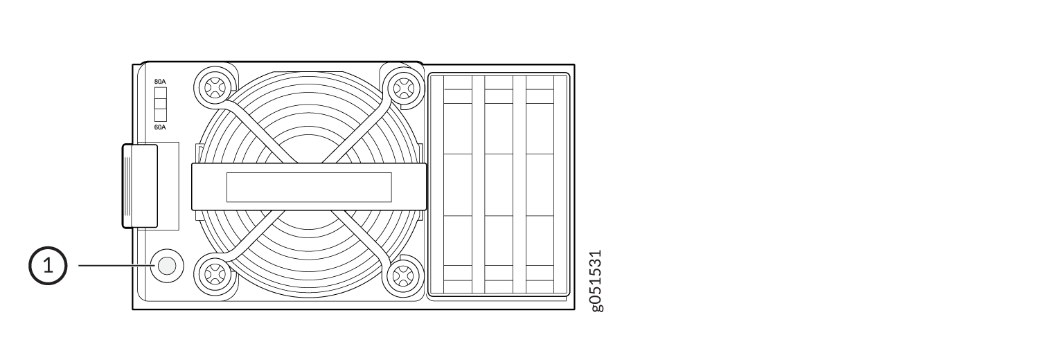
You can install up to two power supplies in the power supply slots in the QFX5230-64CD switch. The power supplies for the QFX5230-64CD switch are located on the FRU panel. Figure 1 shows the FRU panel.
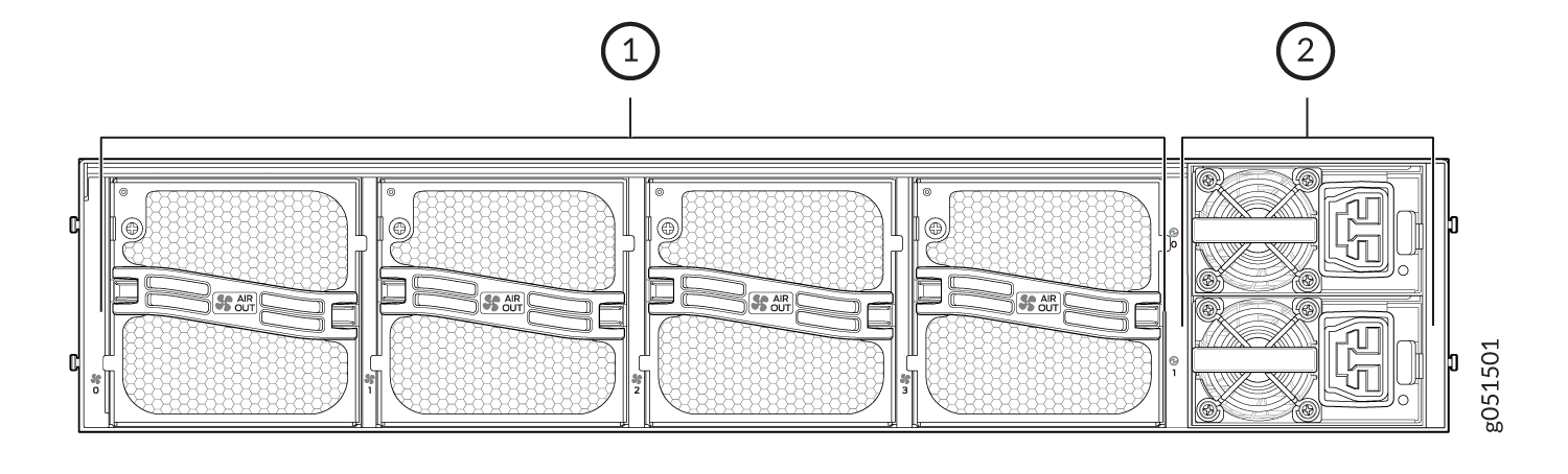
1 — Fans | 2 — Power supplies |
QFX5230-64CD AC Power Supply Description
The AC power supplies in the QFX5230-64CD are hot-removable and hot-insertable field-replaceable units (FRUs) that you can install without powering off the device or disrupting the switching function. QFX5230-64CD support two types of AC power supply modules: FRU-to-port airflow and port-to-FRU airflow models. The handles of the power supplies are color coded.
Figure 2 shows the AC Power Supply Module for QFX5230-64CD switches.
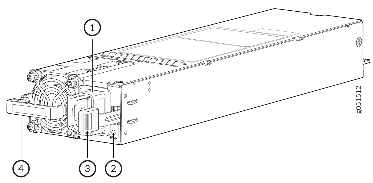
1 — Power connector | 3 — Ejection lever |
2 — Power LED | 4 — Handle |
Verify that the airflow direction on the power supply handle matches the direction of airflow in the chassis. Ensure that each power supply you install in the chassis has the same airflow direction. If you install power supplies with two different airflow directions, Junos Evolved OS raises an alarm. If you need to convert the airflow pattern on a chassis, you must change out all the fans and power supplies at one time to use the new direction.
To avoid electrical injury, carefully follow instructions in Connecting the QFX5230-64CD to Power.
You can get additional information about the status of the power modules using the
show chassis environment psm. For example:
user@device> show chassis environment psm

PSM0 status:
  State                      Online
  Temperature                26 degrees C / 78 degrees F
  Fans                       OK
  DC Output                  OK
  Hours Used 2229
  Firmware Version 0212.0214
  Fan 1 13504
  Fan 2 11904
  Health check Information:
  Status: Not Performed
  Last Result: Not Performed
  Last Execution: Empty
  Next Scheduled Run: 2023-11-29 17:30:02 IST
| Model Number | Airflow Direction | PSM Handle Color |
|---|---|---|
| JNP-3000W-AC-AFO |
Airflow Out (port-to-FRU) |
Juniper Gold |
| JNP-2700W-AC-AFI | Airflow In (FRU-to-port) | Green |
AC Power Cord Specifications
Detachable AC power cords are shipped with the chassis, if you include them as part of your order.
In North America, AC power cords must not exceed 14.75 feet (approximately 4.5 meters) in length, to comply with National Electrical Code (NEC) Sections 400-8 (NFPA 75, 5-2.2) and 210-52, and Canadian Electrical Code (CEC) Section 4-010(3). The cords that can be ordered for the QFX Series switches are in compliance.
Table 2lists AC power cord specifications provided for each country or region.
|
Country/Region |
Electrical Specifications |
Plug Standards |
Juniper Model Number |
|---|---|---|---|
|
Argentina |
16A/250V, 50C |
SAF-D-Grid 400 to IRAM 2073 |
CBL-JNP-SG4-AR |
|
Brazil |
16A/250V, 50C |
SAF-D-Grid 400 to NBR 14136 |
CBL-JNP-SG4-BR |
|
China |
16A/250V, 50C |
SAF-D-Grid 400 to GB2099-1 |
CBL-JNP-SG4-CH |
|
Contintental Europe |
16A/250V, 70C |
SAF-D_Grid 400 to IEC 316P6 |
CBL-JNP-SG4-316P6W |
|
Israel |
16A/250V, 50C |
SAF-D-Grid 400 to SI 32, 3C |
CBL-JNP-SG4-IL |
|
Italy |
16A/250V, 50C |
SAF-D-Grid 400 to CEI 23-50 |
CBL-JNP-SG4-IT |
|
Japan |
20A/250V, 50C |
SAF-D-Grid 400 to NEMA L6-20 |
CBL-JNP-SG4-JPL |
|
North America |
20A/277V, 50C |
SAF-D-Grid 400 to NEMA L7-20P |
CBL-JNP-SG4-HVAC |
|
South Africa |
16A/250V, 50C |
SAF-D-Grid 400 to SANS 164-1 |
CBL-JNP-SG4-SA |
|
South Korea |
16A/250V, 70C |
SAF-D-Grid 400 to RA KSC 8305 | CBL-PWR-C19-KR-2M |
|
Switzerland |
16A/250V, 50C |
SAF-D-Grid 400 to SEV1011 |
CBL-JNP-SG4-SZ |
QFX5230-64CD AC Power Supply LED
The QFX5230-64CD uses a single bi-colored LED to indicate power status.
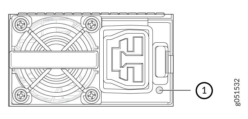
Figure 3 shows the AC power supply LED.
-
Power supply LED
QFX5230-64CD DC Power Supply Description
The DC power supplies in the QFX5230-64CD are hot-removable and hot-insertable field-replaceable units (FRUs) that install without powering off the device or disrupting the switching function. The QFX5230-64CD switch ships with two power supplies. Each power supply provides 3000 W, 2700 W,or 2400 W of power to the chassis (based on the switch model).
Figure 4 shows the DC power supply in a QFX5230-64CD switch.
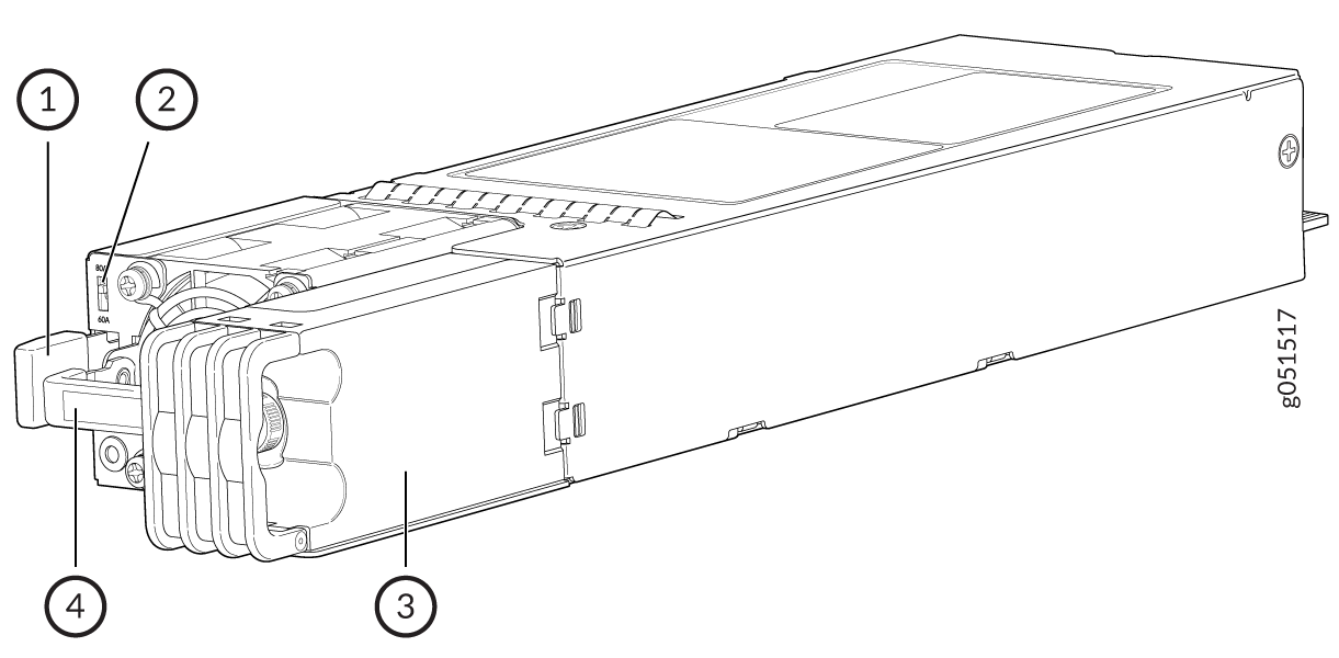
1 — Ejector lever | 3 — Terminal block cover |
2 — DC input current selector (DIP switch) | 4 — Handle |
Table 3 shows the DC power supply summary.
|
Model |
Wattage |
Product Number |
|---|---|---|
|
JNP-2400W-DC-AFI |
2400 W |
740-155850 |
|
JNP-3000W-DC-AFO |
3000 W | 740-073766 |
QFX5230-64CD DC Power Specifications
Table 4shows the DC power specifications of a QFX5230-64CD switch.
|
Model |
Specification |
Rated |
|---|---|---|
|
AFI DC 2400W |
-40V to -72 VDC |
-48 to -60 VDC |
|
AFO DC 3000W |
-40V to -72 VDC |
50-60 Hz |
Verify that the airflow direction on the power supply handle matches the direction of airflow in the chassis. Ensure that each power supply you install in the chassis has the same airflow direction. If you install power supplies with two different airflow directions, Junos Evolved OS raises an alarm. If you need to convert the airflow pattern on a chassis, you must change out all the fans and power supplies at one time to use the new direction.
The connection between each power source and PSM must include a circuit breaker. For single/ multiple feed DC power supply, we recommend that you use a dedicated external circuit breaker for each of the power supplies. Use a 2-pole circuit breaker if both -48V and return feeds are isolated. Use a single pole circuit breaker if one of the feeds are connected to ground. Install this single pole circuit breaker in the ungrounded side of the supply. We recommend that the rating of the circuit breaker is a minimum 125% of the continuous power drawn by each power supply as per the national electric or local code when the system is fully configured. The model number of circuit breaker used for final safety certification is CA2-B0- 16-680-621-BJ with current rating of 80Amps and with long delay. We recommend that you use appropriate rating of the input DC wire taking into consideration continuous current rating of the system when it is fully configured and the circuit breaker rating.
Table 5 shows the electrical charecteristics of the external DC circuit breaker.|
Electrical Characteristics |
Value |
|---|---|
| Breaker | Carling Technologies, CA2-B0- 16-680-621-BJ |
| Delay (short, medium, long). | Long |
| Type of Breaker | Magnetic |
| Voltage rating | 125 VDC |
| Number of Poles | 2-pole |
| Current rating | 80A |
| AIC (interrupt rating) | 5kA |
| Approvals | UL, IEC |
QFX5230-64CD DC Power Supply LEDs
Figure 5 shows the location of the DC power supply LED.
-
DC power supply LED
|
State of LED |
Power Supply Condition |
|---|---|
| Solid Green | Output ON and OK |
| Off | No DC power to all power supplies |
| 1Hz Blink Green | DC input present / Only 12VSB on (PS off) or PS in Cold redundant state |
| Amber | DC cord unplugged; with a second power supply in parallel still with DC input power. |
| Amber |
Power supply critical event causing a shutdown; failure, overcurrent Protection (OCP), overvoltage Protection (OVP), Fan Fail |
| 2Hz Blinking Green | Power supply in firmware upload mode |
Table 7 shows the DC input ratings.
| Parameter | Minimum | Rated | Maximum | Input Switch Setting | Maximum Input Current |
|---|---|---|---|---|---|
| DC Voltage (AFI DC 2400W) | -40 VDC | -48VDC/-60VDC | -72VDC | 60A | 60ADC |
| DC Voltage (AFO DC 3000W) | -40 VDC | -48VDC/-60VDC | -72VDC | 80A | 90ADC |
Table 8 shows the DC output ratings.
| Parameter | Minimum | Maximum | Peak | Unit |
|---|---|---|---|---|
| 12V Main | 0.0 | 250 | 250 | A |
| 12V Standby | 0.0 | 1 | 1 | A |
QFX5230-64CD DC Power Cable Specification
You must supply DC power cables that meet the specifications required by the local code, laws, and standards. The QFX5230-64CD switch supports a 4 AWG and 75 °C temperature-rated stranded copper wire.
You must ensure that power connections maintain the proper polarity.
For field-wiring connections, use copper conductors only.
Make sure that DC power cables do not block access to QFX5230-64CD components or lie on the ground where people can trip on them.