QFX5240 Management Panel
QFX5240 Management Panel Overview
The management panel of the QFX5240 is located to the right of the port panel. See Figure 1 and Figure 2.
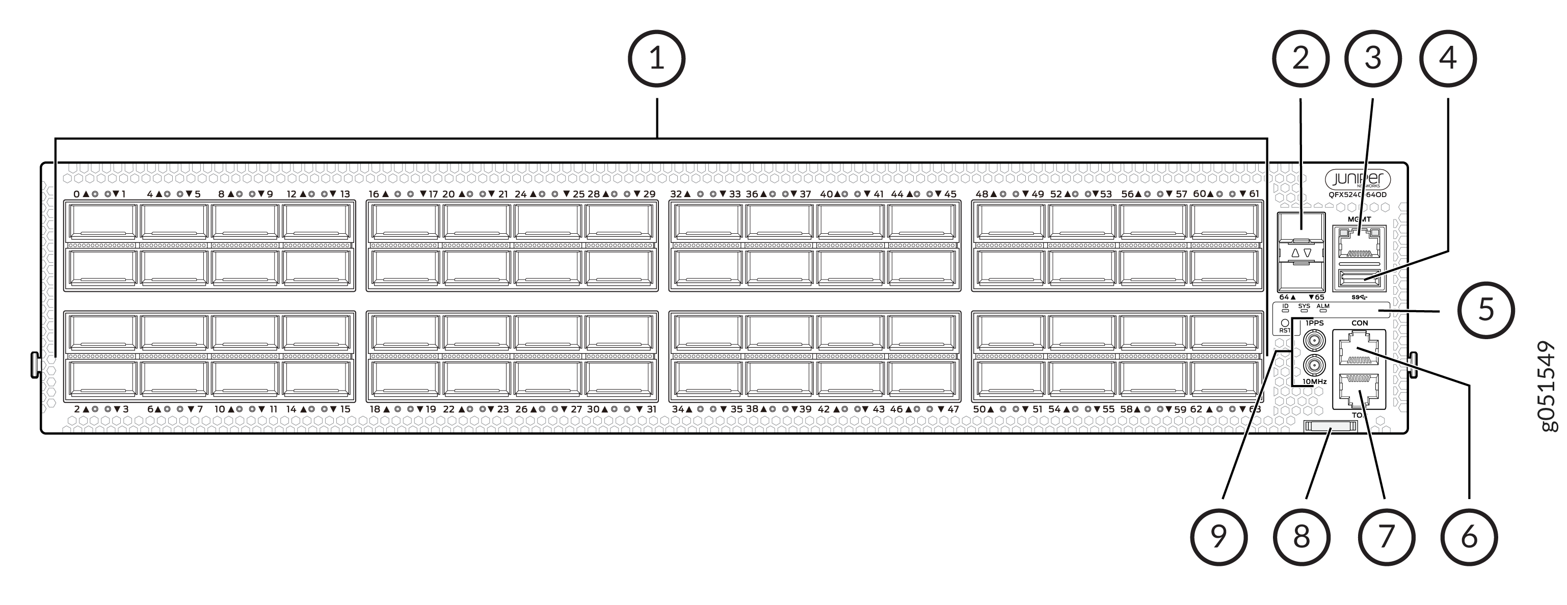
1 — Port Panel | 6 — RJ-45 Console port |
2 — SFP28 Ports | 7 — RJ-45 TOD (Time of Day) port |
3 — RJ-45 Management Port | 8 — Chassis serial number pull-out |
4 — USB Port | 9 — Clock input and output connectors (10 MHz and 1 PPS) |
5 — Status LEDs |
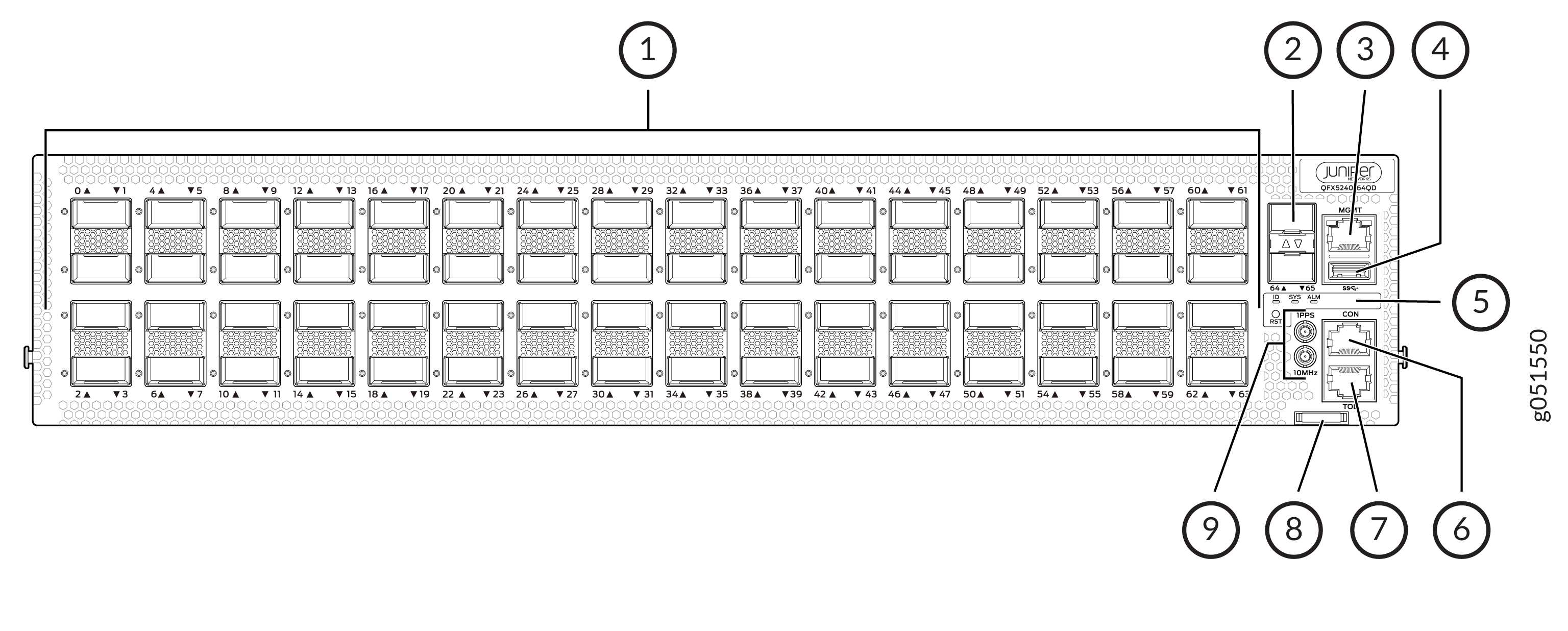
1 — Port Panel | 6 — RJ-45 Console port |
2 — SFP28 Ports | 7 — RJ-45 TOD (Time of Day) port |
3 — RJ-45 Management Port | 8 — Chassis serial number pull-out |
4 — USB Port | 9 — Clock input and output connectors (10 MHz and 1 PPS) |
5 — Status LEDs |
QFX5240 Management Panel LEDs
You can find LEDs on these management panel ports:
-
Chassis status LEDs
-
RJ-45 management port LEDs
The following sections explain how to interpret these LEDs.
QFX5240 Chassis Status LEDs
The QFX5240 has three LEDs that indicate system status. You can find these LEDs to the left of the network ports (see Figure 3 and Figure 4).
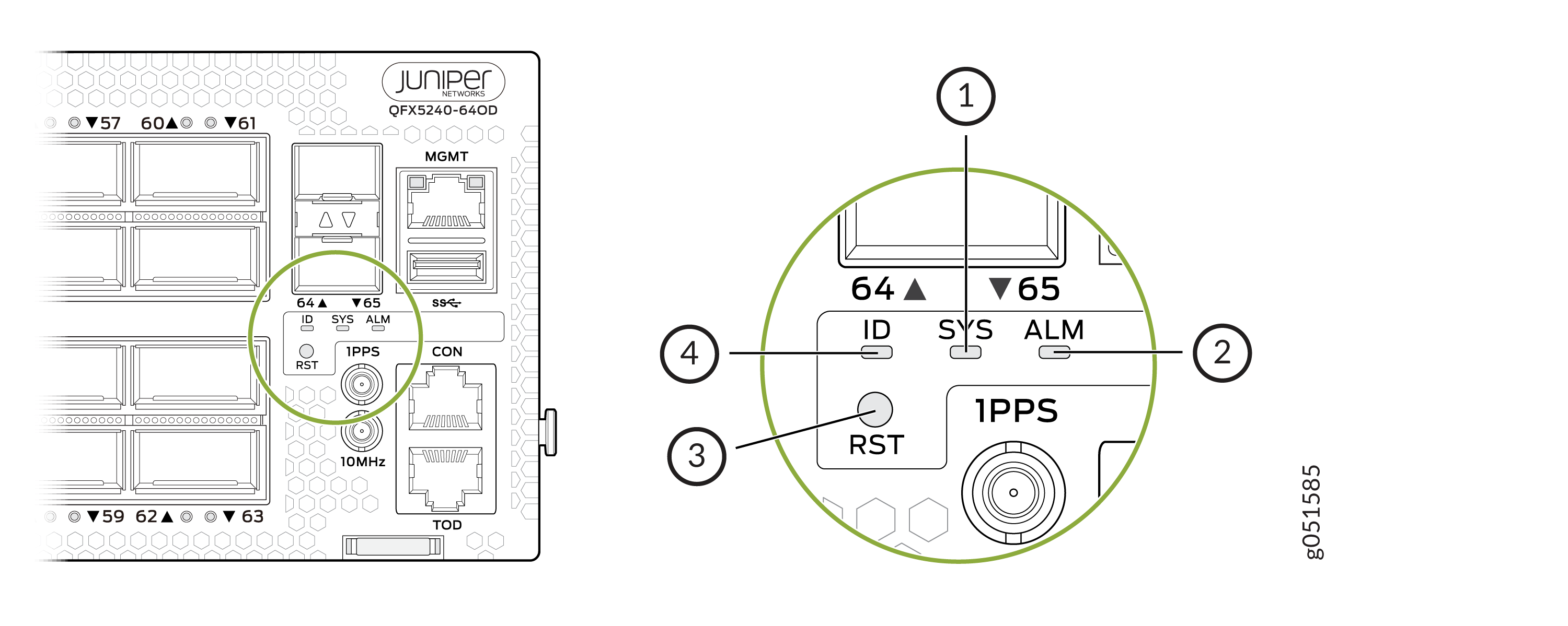
1 — SYS—System status | 3 — RST—Reset button |
2 — ALM—Chassis alarm or fault | 4 — ID-LED |
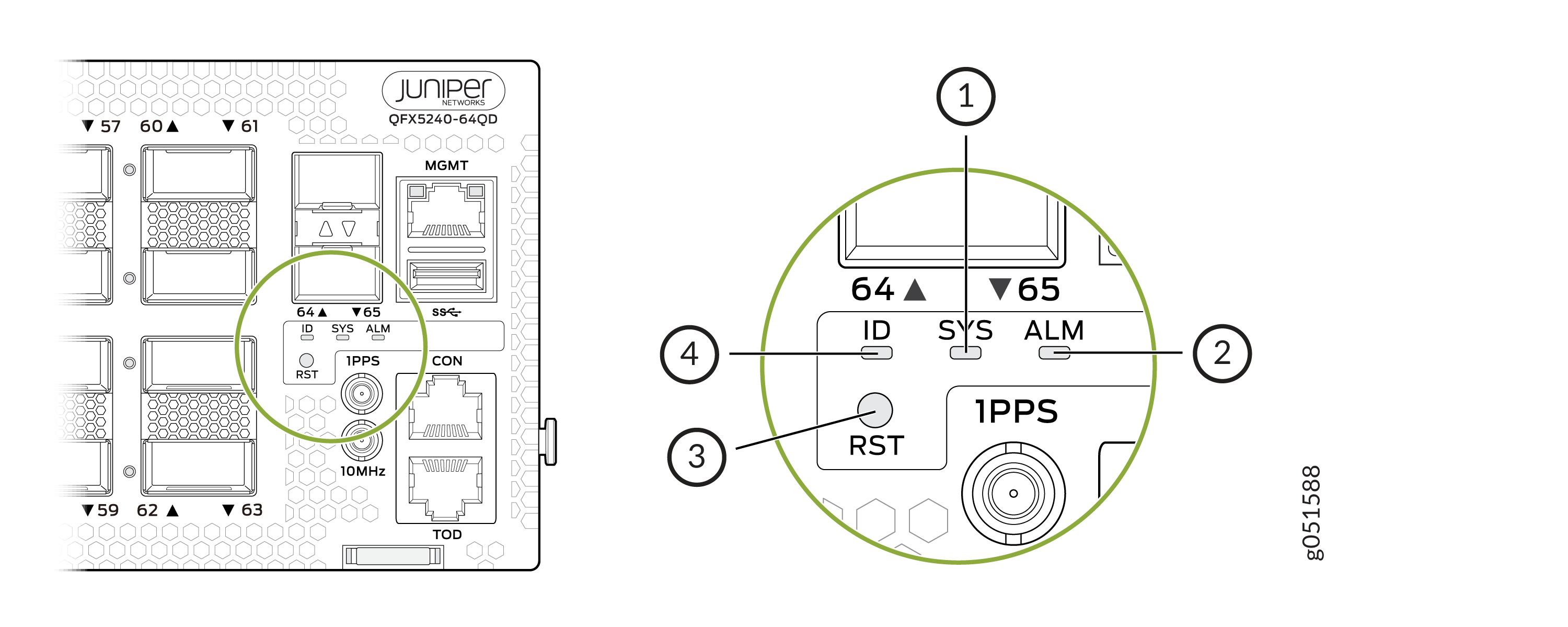
1 — SYS—System status | 3 — RST—Rest button |
2 — ALM—Chassis alarm or fault | 4 — ID-LED |
You can view the colors of the three LEDs remotely through the CLI by issuing the
operational mode command show chassis led.
user@host> show chassis led
 -----------------------------------
LEDs status:
    Alarm LED : Red
    Beacon LED: Off
    System LED: Green

Interface               STATUS LED      LINK/ACTIVITY LED
---------------------------------------------------------
et-0/0/0                N/A             Off
et-0/0/1                N/A             Off
et-0/0/2                N/A             Off
et-0/0/3                N/A             Off
et-0/0/4                N/A             Off
et-0/0/5                N/A             Off
et-0/0/6                N/A             Off
et-0/0/7                N/A             Off
et-0/0/8                N/A             Off
et-0/0/9                N/A             Off
et-0/0/10               N/A             Green
et-0/0/11               N/A             Off
et-0/0/12               N/A             Off
et-0/0/13               N/A             Off
et-0/0/14               N/A             Off
et-0/0/15               N/A             Off
et-0/0/16               N/A             Green
et-0/0/17               N/A             Off
et-0/0/18               N/A             Green
et-0/0/19               N/A             Off
et-0/0/20               N/A             Off
et-0/0/21               N/A             Off
et-0/0/22               N/A             Off
et-0/0/23               N/A             Off
et-0/0/24               N/A             Off
et-0/0/25               N/A             Off
et-0/0/26               N/A             Green
et-0/0/27               N/A             Green
et-0/0/28               N/A             Green
et-0/0/29               N/A             Off
et-0/0/30               N/A             Green
et-0/0/31               N/A             Off
et-0/0/32               N/A             Off
et-0/0/33               N/A             Off
|
Name |
Color |
State |
Description |
|---|---|---|---|
|
ALM–Alarm |
Unlit |
Off |
The switch is halted, or there is no alarm. Note:
The ALM LED glows green during BIOS booting. |
|
Red |
On steadily |
A major hardware fault has occurred, such as a temperature alarm, power failure, or media failure. The device has halted. Power off the device by setting the AC power source outlet to the off (O) position or by unplugging the AC power cords. Correct any voltage or site temperature issues, and allow the switch to cool down. Power on the QFX5240. Monitor the power supply and fan LEDs to help determine where the error is occurring. |
|
|
Amber |
On steadily |
A minor system level alarm has occurred, such as a software error or a missing rescue configuration. Power off the device by setting the AC power source outlet to the off (O) position or by unplugging the AC power cords. Power on the QFX5240, and monitor the status LEDs to ensure that Junos OS Evolved boots properly. |
|
|
SYS–System |
Unlit |
Off |
The device is powered off or halted. Note:
The SYS LED glows green during BIOS booting. |
|
Green |
On steadily |
Junos OS Evolved is loaded on the device. |
|
|
ID–Identification |
Unlit |
Off |
The beacon feature is not enabled on the switch. Enable this feature
by using the Note:
The ID LED glows green during BIOS booting. |
|
Blue |
Blinking |
The beacon feature is enabled on the switch. Disable this feature by
using the |
|
|
Tip:
To find the status of the beacon, use the user@host> show chassis beacon
OFF
|
|||
Management Port LEDs
The RJ-45 management port on a QFX5240 has two LEDs that indicate link status and link activity. The management port is labeled MGMT. See Figure 5.
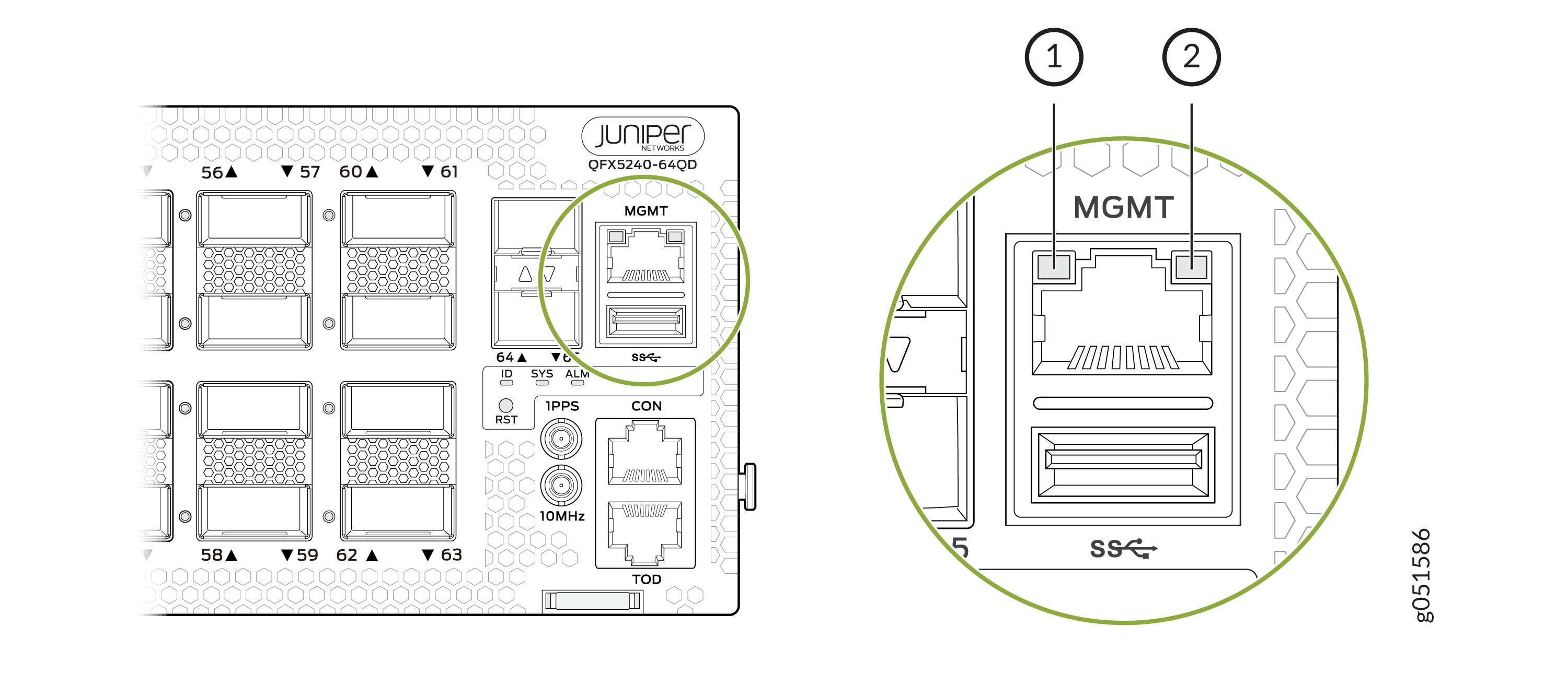
1 — Status LED | 2 — Link activity LED |
|
LED |
Color |
State |
Description |
|---|---|---|---|
|
Link activity |
Unlit |
Off |
No link is established, there is a fault, or the link is down. |
|
Green |
On steadily |
A link is established, but there is no link activity. |
|
|
Blinking or flickering |
A link is established, and there is link activity. |
||
|
Status |
Unlit |
Off |
Either the port speed is 10 Mbps or the link is down. |
|
Green |
On steadily |
The port speed is I Gbps. |
|
|
Green |
On steadily |
The port speed is 100 Mbps. |