Help us improve your experience.

Let us know what you think.

Do you have time for a two-minute survey?


Step 5: Connect External Devices and Network Cables

To connect external devices and network cables:

Connect to a Network for Out-of-Band Management

  1. Turn off the power to the management device.
  2. Plug one end of the RJ-45 Ethernet cable into the appropriate ETHERNET port on the firewall Routing Engine.
  3. Plug the other end of the cable into the network device.

Connect a Management Console

Note:

We no longer include the console cable as part of the device package. If the console cable and adapter are not included in your device package, or if you need a different type of adapter, you can order the following separately:

  • RJ-45 to DB-9 adapter (JNP-CBL-RJ45-DB9)

  • RJ-45 to USB-A adapter (JNP-CBL-RJ45-USBA)

  • RJ-45 to USB-C adapter (JNP-CBL-RJ45-USBC)

If you want to use an RJ-45 to USB-A or RJ-45 to USB-C adapter, you must have the X64 (64-Bit) Virtual COM port (VCP) driver installed on your PC. See https://ftdichip.com/drivers/vcp-drivers/ to download the driver.

  1. Plug one end of the RJ-45 Ethernet cable into the CONSOLE or AUX port on the firewall Routing Engine.
  2. Plug the female DB-9 end into the device’s serial port.

Connect the Network Cables

  1. Have ready a length of the type of cable used by the interface. For cable specifications, see the SRX5600 Firewall Hardware Documentation at www.juniper.net/documentation/.
  2. If the cable connector port is covered by a rubber safety plug, remove the plug.
    Laser Warning:

    Do not look directly into a fiber-optic transceiver or into the ends of fiber-optic cables. Fiber-optic transceivers and fiber-optic cables connected to a transceiver emit laser light that can damage your eyes.

    CAUTION:

    Do not leave a fiber-optic transceiver uncovered except when you are inserting or removing cable. The safety cap keeps the port clean and prevents accidental exposure to laser light.

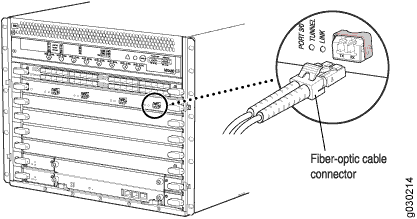
  3. Insert the cable connector into the cable connector port on the faceplate as shown in Figure 1.
    Figure 1: Connect Network CablesConnect Network Cables
  4. Arrange the cable in the cable management system to prevent it from dislodging or developing stress points. Secure the cable so that it is not supporting its own weight as it hangs to the floor. Place excess cable out of the way in a neatly coiled loop in the cable management system. Placing fasteners on the loop helps to maintain its shape.
    CAUTION:

    Avoid bending a fiber-optic cable beyond its minimum bend radius. An arc smaller than a few inches in diameter can damage the cable and cause problems that are difficult to diagnose.

    CAUTION:

    Do not let fiber-optic cables hang free from the connector. Do not allow the fastened loops of a cable to dangle, which stresses the cable at the fastening point.