SRX5800 Chassis
SRX5800 Firewall Chassis
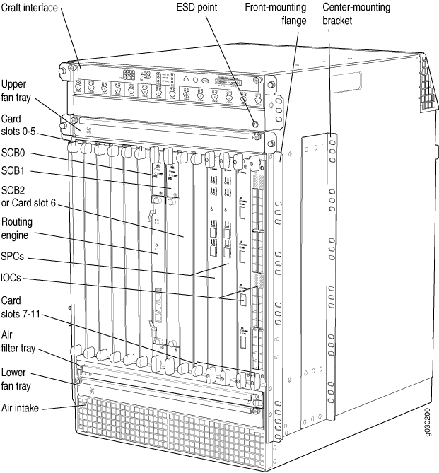
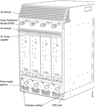
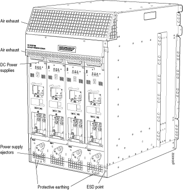
The firewall chassis is a rigid sheet metal structure that houses all the other firewall components (see Figure 1, Figure 2, and Figure 3). The chassis measures 27.75 in. (70.49 cm) high, 17.37 in. (44.11 cm) wide, and 23.0 in. (58.42 cm) deep (from the front-mounting flanges to the rear of the chassis). The chassis installs in 19-in. equipment racks or telco open-frame racks.
The chassis can be installed in standard 800-mm (or deeper) enclosed cabinets when powered by standard-capacity power supplies, or in 1000-mm (or deeper) enclosed cabinets when powered by high-capacity power supplies.
Up to three firewalls can be installed in one standard (48 U) rack if the rack can handle their combined weight, which can be greater than 1,134 lb (515 kg). See SRX5800 Firewall Physical Specifications for physical specifications for the SRX5800 Firewall.
Mounting hardware includes front-mounting flanges on the front of the chassis, and two center-mounting brackets attached to the center of the chassis.
To meet safety and electromagnetic interference (EMI) requirements and to ensure proper operation, you must properly ground the firewall chassis before connecting power. See Grounding the SRX5800 Firewall for instructions.
Before removing or installing components of a firewall, attach an ESD strap to an ESD point and place the other end of the strap around your bare wrist. Failure to use an ESD strap can result in damage to the firewall.
SRX5800 Firewall Physical Specifications
Table 1 summarizes the physical specifications for the firewall chassis.
Description |
Value |
|
|---|---|---|
Chassis dimensions |
Height |
27.75 in. (70.5 cm) high |
Width |
17.37 in. (44.1 cm) wide |
|
Depth, with standard-capacity power supplies |
23.0 in. (58.4 cm) deep from front-mounting bracket to chassis rear 27.8 in. (70.6 cm) total depth including cable management system |
|
Depth, with high-capacity AC power supplies |
25.5 in. (64.8 cm) deep from front-mounting bracket to chassis rear 30.3 in. (77.0 cm) total depth including cable management system |
|
Depth, with high-capacity DC power supplies |
27.8 in. (70.6 cm) deep from front-mounting bracket to chassis rear 32.6 in. (82.8 cm) total depth including cable management system |
|
Firewall weight |
Chassis with midplane, fan tray, air filter, and cable manager: 150 lb (60.4 kg) Maximum configuration: 400 lb (182 kg) |
|
Routing Engine weight |
SRX5K-RE-13-20: 2.4 lb (1.1 kg) SRX5K-RE-1800X4: 2.4 lb (1.1 kg) |
|
SCB weight |
SRX5K-SCB: 9.6 lb (4.4 kg) SRX5K-SCBE: 9.6 lb (4.4 kg) SRK5K-SCB3: 10.14 lb (4.6 kg) |
|
MPC weight (with two MICs) |
13.1 lb (5.9 kg) |
|
IOC weight |
13.1 lb (5.9 kg) |
|
Craft interface weight |
1.1 lb (0.5 kg) |
|
Fan tray weight |
4.2 lb (1.9 kg) |
|
Air filter weight |
1.0 lb (0.5 kg) |
|
Cable management weight |
0.3 lb (0.14 kg) |
|
Standard-capacity DC power supply weight (only supported on devices with SRX5K-SCB and SRX5K-RE-13-20) |
3.8 lb (1.7 kg) |
|
High-capacity DC power supply weight |
12.0 lb (5.5 kg) |
|
Standard-capacity AC power supply weight (only supported on devices with SRX5K-SCB and SRX5K-RE-13-20) |
5.0 lb (2.3 kg) |
|
High-capacity AC power supply weight |
12.0 lb (5.5 kg) |
|
For the weights of specific cards, Routing Engines, or port modules, see the SRX5400, SRX5600, and SRX5800 Firewall Card Guide at www.juniper.net/documentation/.
SRX5800 Firewall Midplane Description
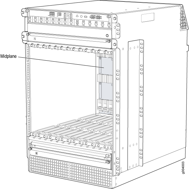
The midplane is located toward the rear of the chassis and forms the rear of the card cage (see Figure 4). IOCs, SPCs, and SCBs install into the midplane from the front of the chassis, and the power supplies install into the midplane from the rear of the chassis. The cooling system components also connect to the midplane.
The midplane performs the following major functions:
-
Data path—Data packets are transferred across the midplane between the IOCs and SPCs through the fabric ASICs on the SCBs.
-
Power distribution—The power supplies are connected to the midplane, which distributes power to all the firewall components.
-
Signal path—The midplane provides the signal path to the IOCs, SCBs, SPCs, Routing Engine, and other system components for monitoring and control of the system.
The enhanced midplane supports Junos OS Release15.1X49-D10. It provides greater per-slot fabric performance and signal integrity, along with error-free high speed data transfer, and it reduces cross-talk. The midplane supports link speeds up to 10 Gbps and is not field replaceable.
SRX5800 Firewall Cable Manager Description
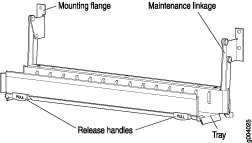
The cable management system (see Figure 5) is a tray located below the card cage that has a row of fourteen dividers for securing the cables for each card. Features in the cable management tray allow you to gently secure the cables with cable strips or other ties. To secure the cables in place, loop the tie through the cable anchor and secure the tie.
You can pull the cable management system up and outward to lock it into the maintenance position. This allows you to access the lower fan tray and the air filter.
SRX5800 Firewall Craft Interface Overview
The craft interface shows you status and troubleshooting information at a glance and lets you perform many system control functions (see Figure 6). It is hot-insertable and hot-removable. The craft interface is located on the front of the firewall above the upper fan tray.

The craft interface draws its power from the SCBs installed in the SCB slots 0, 1, and 2 at the center of the card cage. At least one SCB must be installed in the firewall for the craft interface to obtain power.
SRX5800 Firewall Craft Interface Alarm LEDs and Alarm Cutoff/Lamp Test Button
Two large alarm LEDs are located at the upper right of the craft interface. The circular red LED lights to indicate a critical condition that can result in a system shutdown. The triangular yellow LED lights to indicate a less severe condition that requires monitoring or maintenance. Both LEDs can be lit simultaneously. A condition that causes an LED to light also activates the corresponding alarm relay contact on the craft interface.
To deactivate the red and yellow alarms, press the button labeled ACO/LT (for “alarm cutoff/lamp test”), which is located to the right of the alarm LEDs. Deactivating an alarm turns off both LEDs and deactivates the device attached to the corresponding alarm relay contact on the craft interface.
Table 2 describes the alarm LEDs and alarm cutoff button in more detail.
Shape |
Color |
State |
Description |
|---|---|---|---|
 |
Red |
On steadily |
Critical alarm LED—Indicates a critical condition that can cause the device to stop functioning. Possible causes include component removal, failure, or overheating. |
 |
Yellow |
On steadily |
Warning alarm LED—Indicates a serious but nonfatal error condition, such as a maintenance alert or a significant increase in component temperature. |
 |
– |
– |
Alarm cutoff/lamp test button—Deactivates red and yellow alarms. Causes all LEDs on the craft interface to light (for testing) when pressed and held. |
SRX5800 Firewall Craft Interface Host Subsystem LEDs
The host subsystem has three LEDs, located in the middle of the craft interface, that indicate its status. The LEDs labeled RE0 show the status of the Routing Engine and SCB in slot 0 .
The LEDs labeled RE1 show the status of the Routing Engine and SCB in slot 1. Table 3 describes the functions of the host subsystem LEDs.
Label |
Color |
State |
Description |
|---|---|---|---|
MASTER |
Green |
On steadily |
Host is functioning as the master. |
ONLINE |
Green |
On steadily |
Host is online and is functioning normally. |
OFFLINE |
Red |
On steadily |
Host is installed but the Routing Engine is offline. |
Off |
Host is not installed. |
SRX5800 Firewall Craft Interface Power Supply LEDs
Each power supply has two LEDs on the craft interface that indicate its status. The LEDs, labeled 0 through 3, are located near the middle of the craft interface next to the PEM label. Table 4 describes the functions of the power supply LEDs on the craft interface.
Label |
Color |
State |
Description |
|---|---|---|---|
PEM |
Green |
On steadily |
Power supply is functioning normally. |
Red |
On steadily |
Power supply has failed or power input has failed. |
SRX5800 Firewall Craft Interface Card OK/Fail LEDs
Each slot in the card cage has a pair of LEDs on the craft interface that indicates the status of the card installed in it. The card LEDs are located along the bottom edge of the craft interface and are labeled as follows:
0 through 5 on the left
0 and 1 for the two center slots reserved for SCBs
2/6 and 7 through 11 on the right
Table 5 describes the functions of the OK and Fail LEDs.
Label |
Color |
State |
Description |
|---|---|---|---|
OK |
Green |
On steadily |
The card is functioning normally. |
Blinking |
The card is transitioning online or offline. |
||
Off |
The card is not online. |
||
FAIL |
Red |
On steadily |
The card has failed. |
SRX5800 Firewall Craft Interface Fan LEDs
Each fan LED is located on the top left of the craft interface. Table 6 describes the functions of the fan LEDs.
Label |
Color |
State |
Description |
|---|---|---|---|
OK |
Green |
On steadily |
Fan tray is functioning normally. |
FAIL |
Red |
On steadily |
Fan tray has failed. |
SRX5800 Firewall Craft Interface Online Buttons
The craft interface has a row of Online/Offline buttons along its lower edge. Each button corresponds to one slot in the card cage. The Online/Offline buttons are only supported for slots containing MPC interface cards. You can install MPCs into slots:
SRX5400–Any slot except bottom slot 0
SRX5600–Any slot except bottom slots 0 or 1
SRX5800–Any slot except center slots 0 or 1
The Online/Offline buttons are not supported for removal and replacement of SPCs or SCB.
While traffic is passing through the Firewall, particularly if the device is configured as part of a high availability (HA) cluster, we strongly recommend that you do not push any of the Online/Offline buttons.
To take an MPC offline using the Online/Offline buttons:
Press and hold the corresponding card’s Online/Offline button on slot 1 on the craft interface. The green OK/FAIL LED next to the button begins to blink. Hold until both the button’s LED and the MPC’s LED are off.
Issue the CLI
show chassis fpccommand to check the status of installed MPCs. As shown in the sample output, the value Offline in the column labeled State indicates that the MPC in slot 1 is now offline:user@host> show chassis fpc Slot State (C) Total Interrupt DRAM (MB) Heap Buffer 0 Online 35 4 0 1024 13 25 1 Online 47 3 0 1024 13 25 2 Online 37 8 0 2048 18 14
An MPC can also be taken offline via CLI command:
user@host> request chassis fpc slot 2 offline node0: -------------------------------------------------------------------------- Offline initiated, use "show chassis fpc" to verify {primary:node0}user@host> show chassis fpc node0: -------------------------------------------------------------------------- Temp CPU Utilization (%) Memory Utilization (%) Slot State (C) Total Interrupt DRAM (MB) Heap Buffer 0 Online 35 7 0 1024 13 25 1 Online 46 4 0 1024 13 25 2 Offline ---Offlined by cli command--- After pushing MPC online button:user@host> show chassis fpc Temp CPU Utilization (%) Memory Utilization (%) Slot State (C) Total Interrupt DRAM (MB) Heap Buffer 0 Online 34 5 0 1024 13 25 1 Online 46 3 0 1024 13 25 2 Offline ---Offlined by button press---
To bring an MPC back online using the Online/Offline buttons:
Press and hold the corresponding card’s Online/Offline button on slot 1 on the craft interface. The green OK/FAIL LED next to the button and the MPC’s LED begins to blink. Hold until both the button’s LED and the MPC’s LED are green and steady.
Issue the CLI
show chassis fpccommand to check the status of installed MPCs. As shown in the sample output, the value Online in the column labeled State indicates that the MPC in slot 1 is functioning normally:Verify if the MPC is offline:
user@host> show chassis fpc
node0:
--------------------------------------------------------------------------
                     Temp  CPU Utilization (%)   Memory    Utilization (%)
Slot State            (C)  Total  Interrupt      DRAM (MB) Heap     Buffer
  0  Online            37     23          0       2048       19         14
  1  Offline         ---Offlined by cli command---
  2  Online            49     37          0       1024       14         25
The command output indicates the MPC is offline.
Bring the MPC online for the first time by using the following CLI command:
user@host> request chassis fpc slot 1 online
node0:
--------------------------------------------------------------------------
Online initiated, use "show chassis fpc" to verify
Verify that the MPC is online:
user@host> request chassis fpc slot 1 online
node 0
node0:
--------------------------------------------------------------------------
FPC 1 already online
The command output indicates the MPC is online.
Confirm that the MPC in the chassis is online:
user@host> show chassis fpc
node0:
--------------------------------------------------------------------------
                     Temp  CPU Utilization (%)   Memory    Utilization (%)
Slot State            (C)  Total  Interrupt      DRAM (MB) Heap     Buffer
  0  Online            37      6          0       2048       19         14
  1  Online            44     11          0       1024       23         29
  2  Online            49     22          0       1024       14         25
SRX5800 Firewall Craft Interface Alarm Relay Contacts
The craft interface has two alarm relay contacts for connecting the device to external alarm devices (see Figure 7). Whenever a system condition triggers either the major or minor alarm on the craft interface, the alarm relay contacts are also activated. The alarm relay contacts are located on the upper right of the craft interface.
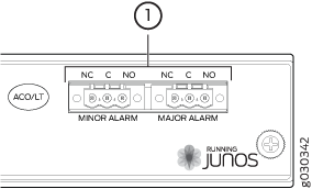
The alarm relay contacts consist of two sets of connectors, one set for each of the two alarms (major and minor). For each alarm color there are three connectors. Table 7 describes the functions of the connectors.
Contact Label |
Contact Name |
Function |
|---|---|---|
NC |
Normally Closed |
Connects the alarm relay to an external alarm-reporting device that activates when the circuit between C and NC is closed. |
C |
Current In |
Connects the alarm relay to the current source for the external alarm-reporting device. |
NO |
Normally Open |
Connects the alarm relay to an external alarm-reporting device that activates when the circuit between C and NC is open. |
Table 8 shows the electrical specifications for the alarm relay contacts.
Current Type |
||
|---|---|---|
AC |
DC |
|
Maximum Voltage |
250 |
30 |
Maximum Current |
8 A |
|
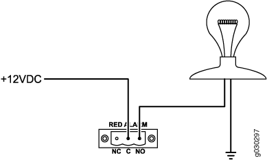
Figure 8 shows an example wiring diagram for a simple alarm reporting device. In this case the device is a 12-volt light bulb that illuminates when the device encounters a condition that activates the major alarm LED and relay contacts. The alarm relay contacts can also be used to activate other devices such as bells or buzzers.
