Interface maps bridge the capabilities in logical devices with
the vendor specifications in device profiles.
-
From the left navigation menu, navigate to Design > Interface
Maps and click Create Interface Map.
-
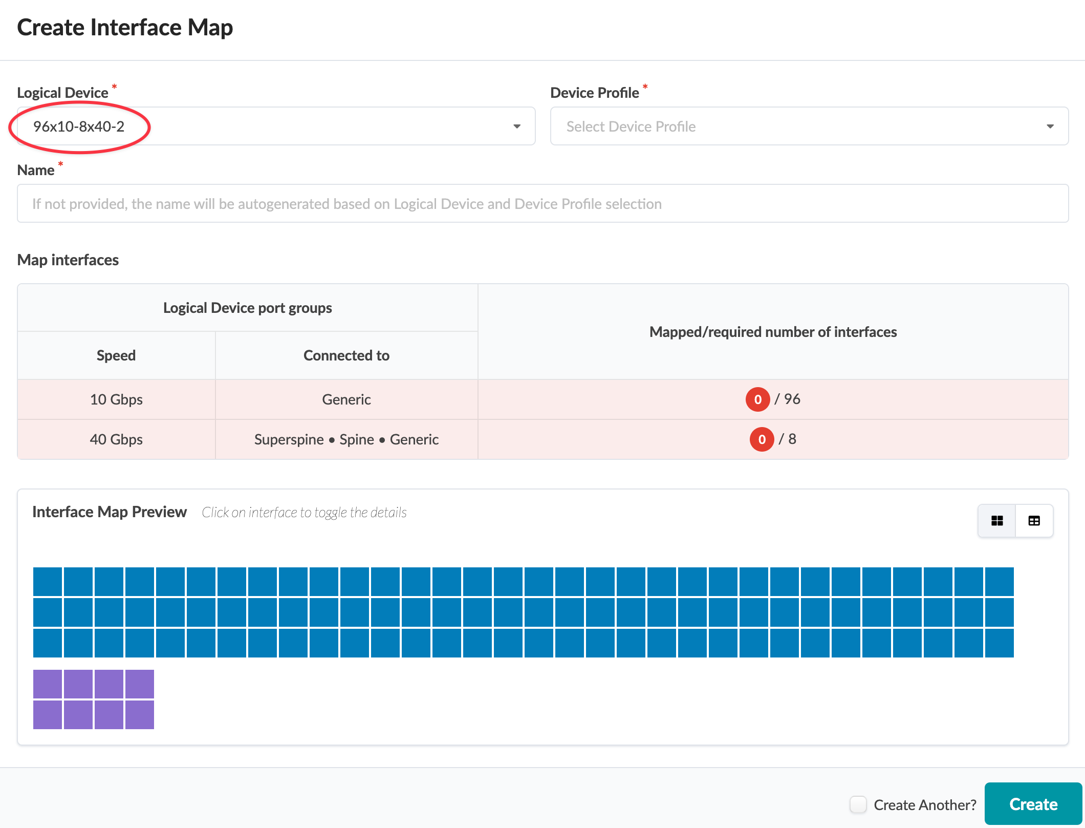
In the dialog that opens, select a logical device from the Logical Device
drop-down list.
We're using a custom logical device, 96x10-8x40-2 for our example. If you'd like
to follow along, you can create the logical device before continuing. This logical device has 96 - 10
GbE ports for generic systems (servers) and 8 - 40 GbE ports for uplinks to superspines,
spine switches or generic systems (external routers).
The Map interfaces table shows each port group, their speed and roles. The red
color indicates that the interfaces haven't been mapped yet.
-
Select a device profile that matches the logical device capabilities from the Device
Profile drop-down list.
In our example, we're creating an interface map to create dense server connectivity.
We'll select Arista DCS-7050QX-32. This device has 24 - 40 GbE QSFP+ ports that
are transformable (4x10 GbE or 1x40 GbE) and 8 - 40 GbE QSFP+ ports that are not
transformable. Our plan is to break out the 24 - 40 GbE transformable ports to 96 - 10
GbE ports.
-
As soon as both the logical device and device profile are selected the interface map
name is automatically populated. The auto-generated name consists of the concatenation of
the names of the selected logical device and device profile. If you prefer, you can enter
your own unique name (64 characters or fewer).
-
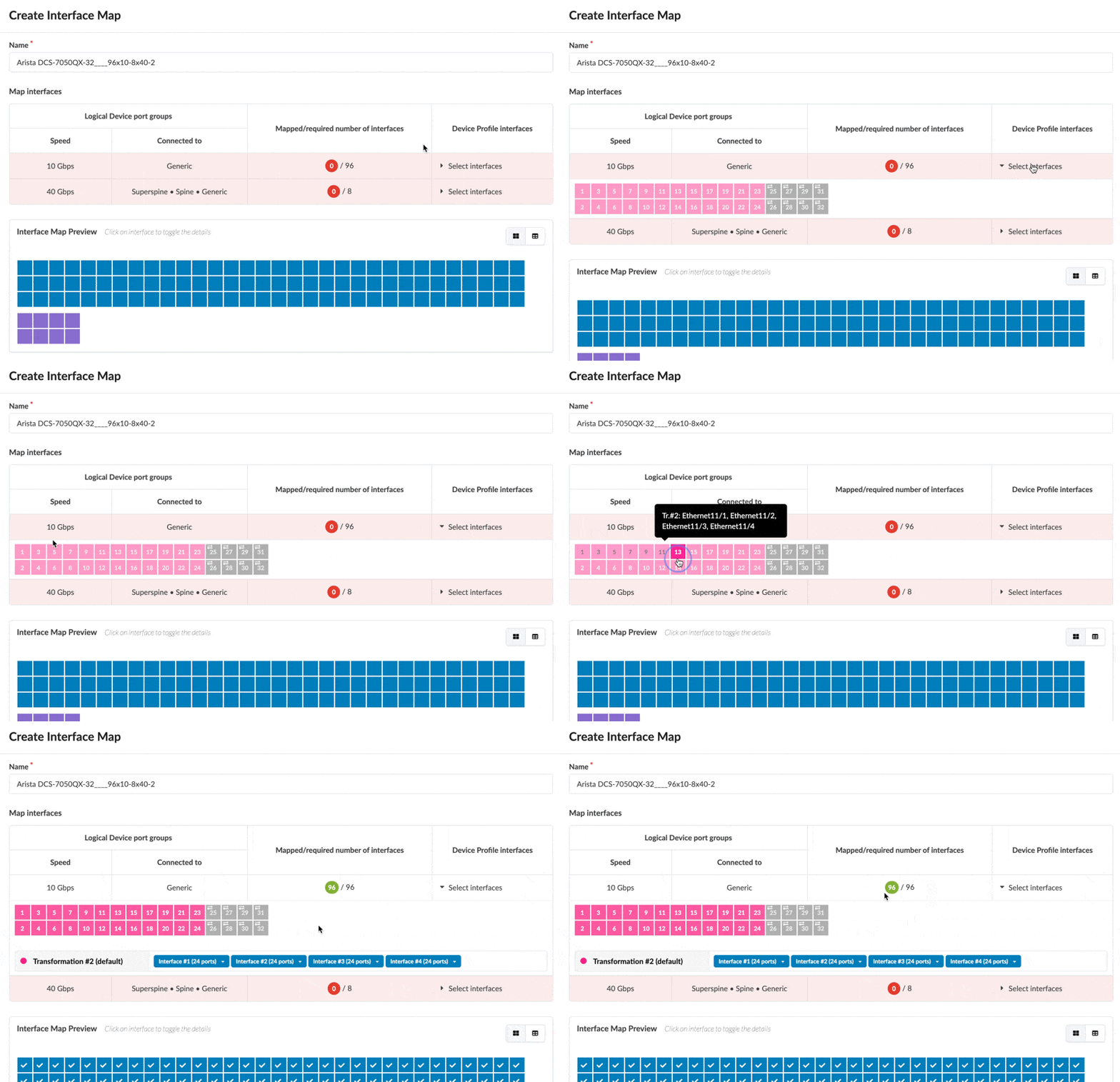
Now let's map the interfaces. In the first port group row, in the Device Profile
Interfaces column, click Select interfaces, then in the port
layout that appears, drag from the first port to the 24th port to select them. As you
select ports the white numbers turn gray. After you've selected them, check marks appear
on the applicable ports in the Interface Map Preview. When all interfaces are
selected the red circle turns green.
-
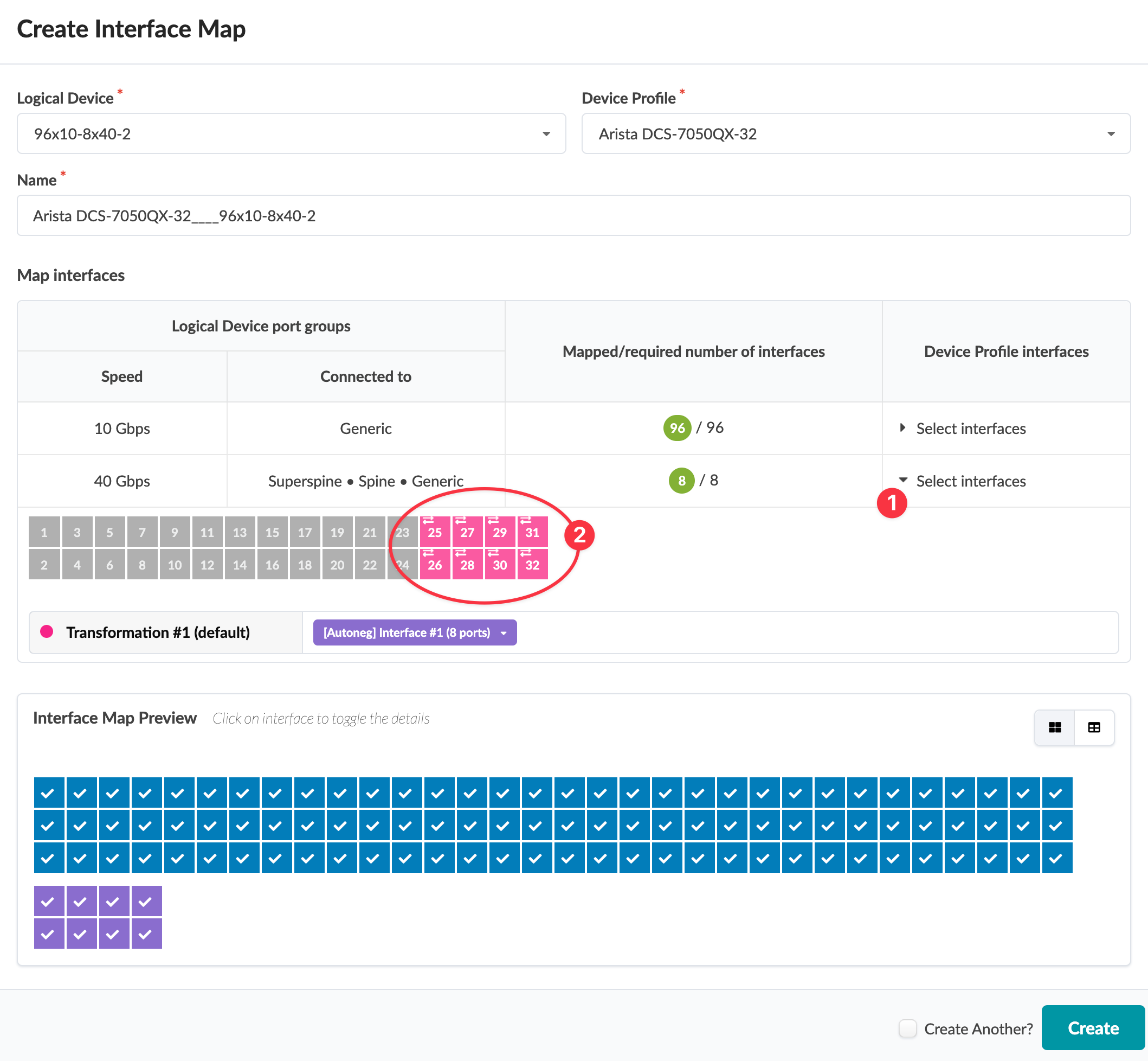
For the second port group, click Select interfaces, then in the
port layout that appears, drag to select the remaining 8 ports .
-
Click Create to create the interface map and return to the table
view.


