Help us improve your experience.

Let us know what you think.

Do you have time for a two-minute survey?


Configure Virtual Networks for Multi-tenant Service Operations

This section shows how to configure Layer 2 and Layer 3 multi-tenant network services on two virtual networks, blue and green as shown in Figure 1.

This is a typical day one operation that provides virtual network connectivity that isolates traffic between the virtual networks while allowing bridged or routed connectivity for devices in the same virtual network.

To create the Green and Blue networks in Contrail Command, we will configure the following:

  • Four virtual networks, two Green and two Blue

  • Four VPGs to add the access interfaces to the servers

  • Two Logical Routers (LRs) for inter-VN communication, one for the Green virtual network and one for the Blue virtual network

Figure 1: Green and Blue Virtual NetworksGreen and Blue Virtual Networks

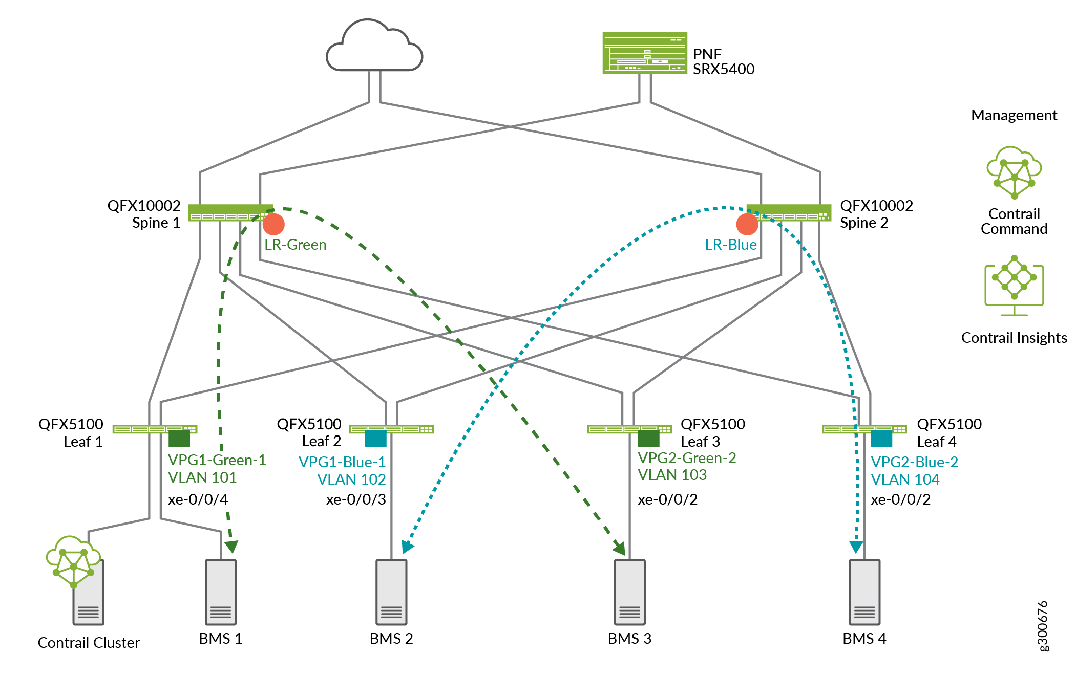
At this point we do not have communication between the green and blue networks. LRs cannot connect to other LRs. For inter-LR, or inter-tenant communication, you need to connect the LRs using service chaining. See Configure Service Chaining With PNF.

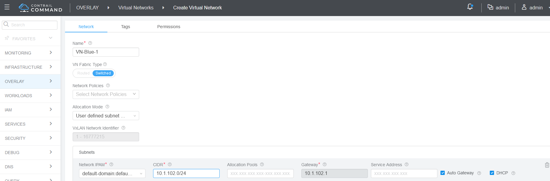
Create Virtual Networks

A virtual network in the Contrail environment allows hosts in the same network to communicate with each other. This is similar to assigning a VLAN to each host so that hosts on the same VLAN can reach each other.

In this section, we will create four virtual networks, two for the green network and two for the blue virtual network.

To configure a virtual network:

  1. Navigate to Overlay > Virtual Networks and click Create.
  2. Fill in the following fields to define four virtual networks. By default Contrail Networking uses the first available host ID in the subnet for that subnet’s default gateway. As a result it’s good practice to avoid assigning host ID 1 to VMs or BMSs.

    Name:

    Allocation Mode

    Subnets

    Network IPAM

    CIDR

    Gateway

    VN-Green-1

    Default setting of “User defined subnet only”

    Default-domain:default-project:default

    10.1.101.0/24

    10.2.4.1

    VN-Green-2

    Default setting of “User defined subnet only”

    Default-domain:default-project:default

    10.1.103.0/24

    10.2.3.1

    VN-Blue-1

    Default setting of “User defined subnet only”

    Default-domain:default-project:default

    10.1.102.0/24

    10.2.2.1

    VN-Blue-2

    Default setting of “User defined subnet only”

    Default-domain:default-project:default

    0.1.104.0/24

    10.2.4.1

  3. When both virtual networks are created, the Virtual Networks screen displays. You will see that both the green and blue networks are available.

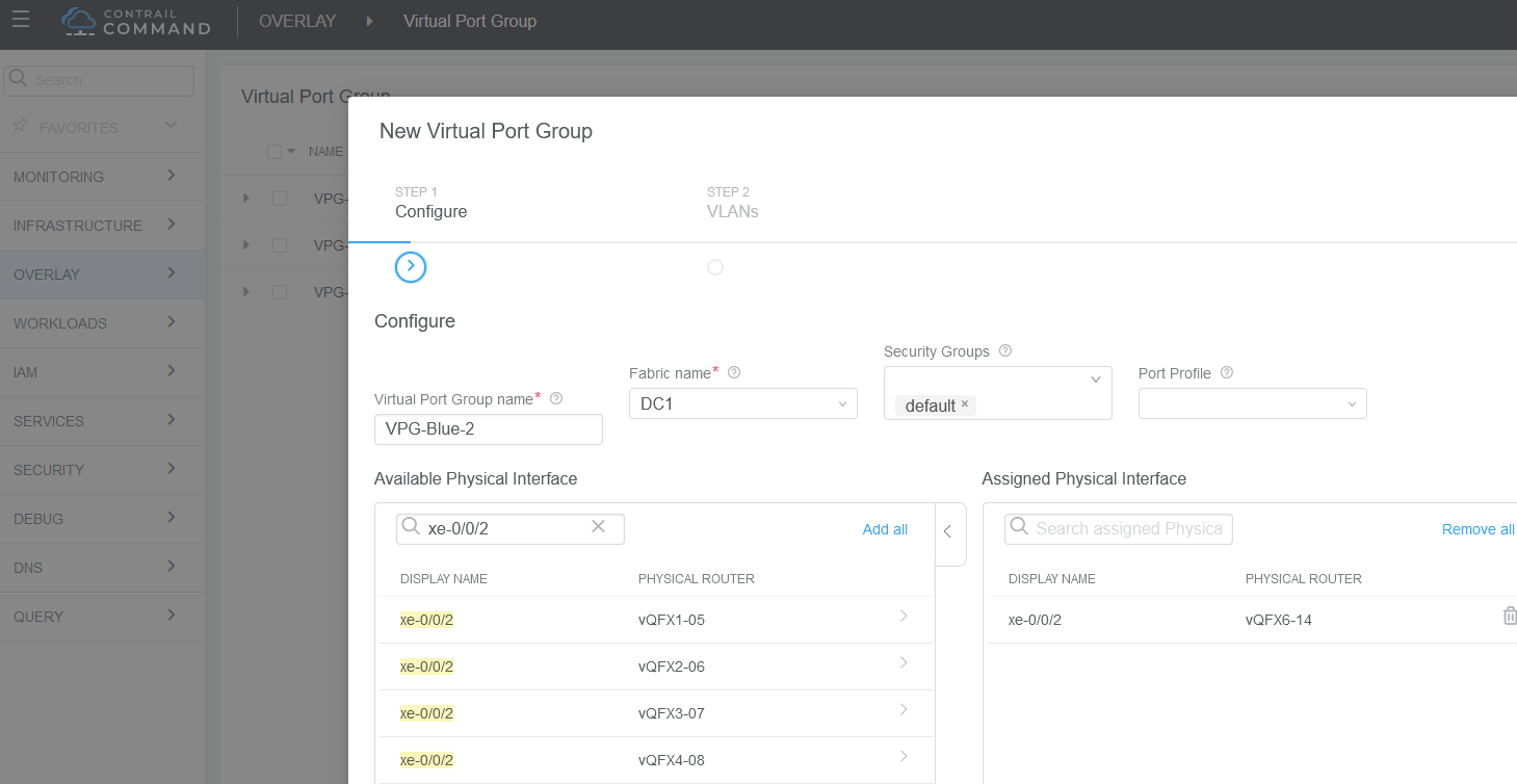
Assign Interfaces to VLANs with Virtual Port Groups

You configure VPGs to add interfaces to your virtual networks. In this section, we will add the access interfaces from the leaf devices to the servers as shown in Figure 2.
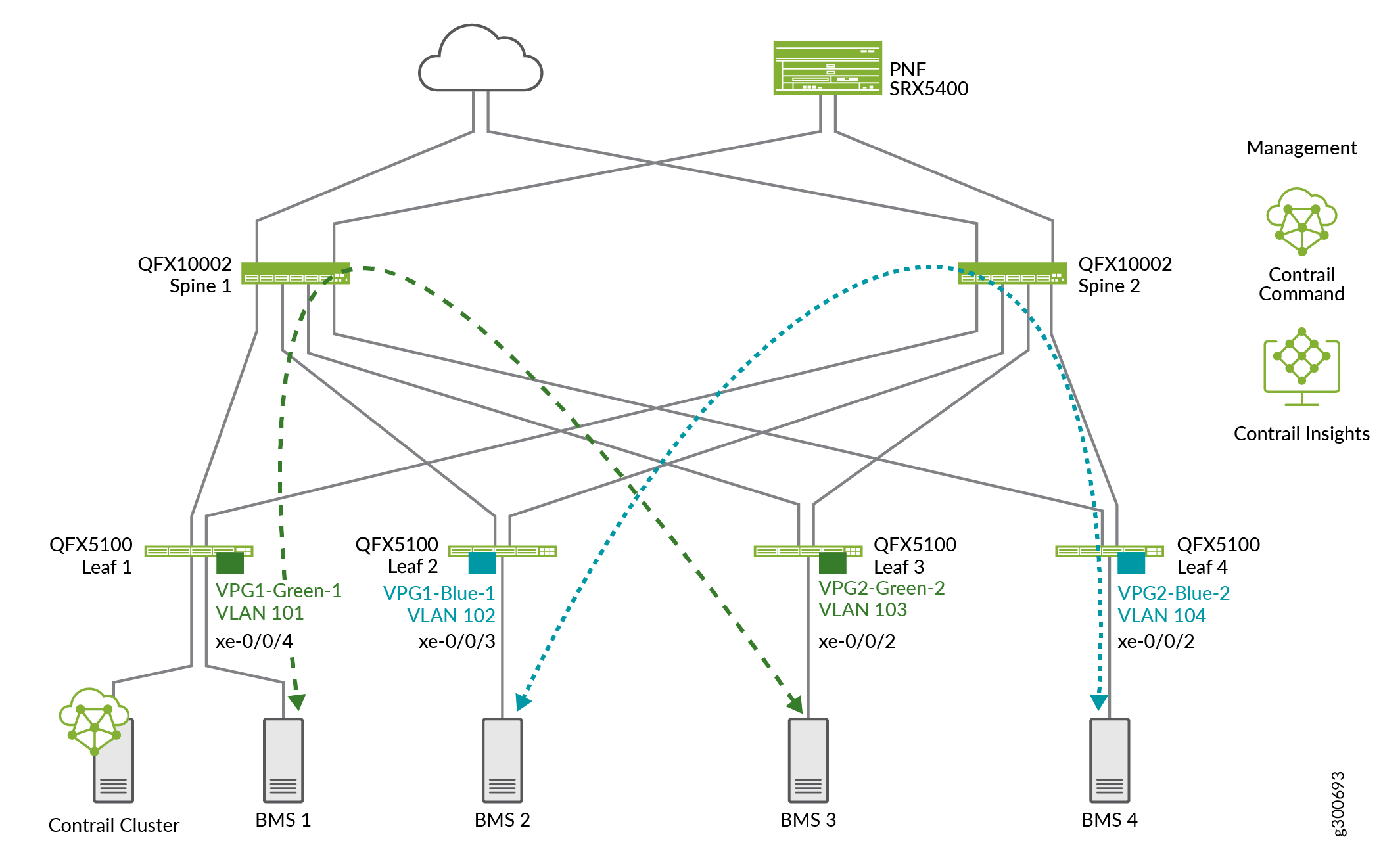
Figure 2: Adding VPGs to Virtual NetworksAdding VPGs to Virtual Networks

To create a VPG:

  1. Navigate to Overlay > Virtual Port Group and click Create.
  2. Create four VPGs with the values shown in the following table.

    To assign a physical interface, find the interface under Available Physical Interface. There can be multiple pages of interfaces. To move an interface to the Assigned Physical Interface, click the > next to the interface.

    Virtual Port Group Name

    VPG1-Green-1

    VPG2-Green-2

    VPG1-Blue-1

    VPG2-Blue-2

    Fabric Name

    DC1

    DC1

    DC1

    DC1

    Assigned Physical Interface

    xe-0/0/4:0

    xe-0/0/2:0

    xe-0/0/3:0

    xe-0/0/2:0

  3. Click Next.

    The screen to add VLANs appears.

  4. To create VLANs on the VPGs, create the following VLANs.

    Virtual Network

    VLAN IDs

    VN-Green-1

    101

    VN-Green-2

    103

    VN-Blue-1

    102

    VN-Blue-2

    104

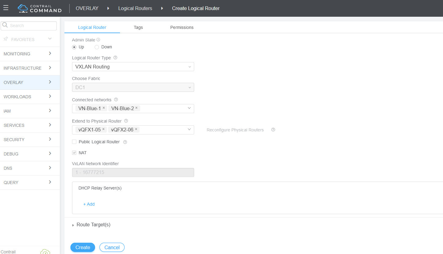
Enable Layer 3 Routing on Virtual Networks Using Logical Routers

CEM uses logical routers (LRs) to enable routing on virtual networks. It does so by creating a VRF routing instance for each logical router with IRB interfaces on the spine devices. After CEM configures the devices, network traffic from the blue and green networks travels over a VXLAN tunnel from the leaf devices to the spine devices. At the spine devices, the traffic is routed at Layer 3.

In this section, we will enable routing on the blue and the green virtual networks as shown in Figure 3.

Figure 3: Adding Logical Routers to the Virtual NetworksAdding Logical Routers to the Virtual Networks

To configure the logical routers:

  1. Navigate to Overlay > Logical Routers, and click Create.
  2. Create two logical routers as shown in the following table:

    Name

    LR-Blue

    LR-Green

    Extend to Physical Router

    DC2-Spine1

    DC2-Spine2

    DC2-Spine1

    DC2-Spine2

    Logical Router Type

    VXLAN Routing

    VXLAN Routing

    Connected Networks

    Blue-1

    Blue-2

    Green-1

    Green-2

Verify Your Virtual Network Configuration

  1. On a spine device, check that IRB interfaces are configured. There are two IRBs for each virtual network.
  2. On a spine device, check that VLANs are configured.
  3. On a spine device, check that VRFs are configured, one for the green network and one for the blue network. Note that the IRB interfaces are added to the VRFs.
  4. When you have finished your configuration, you can run ping between servers in the same virtual network. For example, run ping from BMS1 to BMS3 in the green network.
  5. Run ping from BMS2 to BMS4 in the blue network.