Contrail Enterprise Multicloud Components
This section provides an overview of the components used in this solution. The implementation of each component is covered in later sections of this guide.
Contrail Command
Contrail Command is the CEM user interface that provides a user-friendly interface that lets you provision your private data center network and extend it to the public cloud. It automates the process of building a new data center from scratch, adding an overlay to an existing IP fabric, and providing switching, routing, and security services. As a result, Contrail Command is a powerful component of the CEM solution.
Contrail Command provides an intuitive user interface for the user—whether a network operation administrator, a cloud administrator, or a tenant administrator—to perform any infrastructure and service operations on the managed multicloud infrastructure. Some of the infrastructure and troubleshooting operations that you can perform with Contrail Command are:
Performs Junos OS upgrades on devices in the fabric.
Automates service operations, such as provisioning VLANs on access ports, inter-subnet routing services, advanced inter-tenant services, across the fabric, and extending those services across physical and virtualized endpoints
Automates maintenance and scale out procedures of the fabric (adding devices to the fabric, replacing failed devices, diverting traffic from devices)
Collects flow usage counters, streaming telemetry, alarms, counters from the devices and providing a view on how the infrastructure and the multitenant services are performing, identifying capacity bottlenecks or traffic anomalies with respect to the baseline
Provides workflows and methods to proactively identify issues and faults, correlate them and take corrective actions.
See Also
IP Fabrics
An IP fabric is a set of devices and physical network functions (PNFs) that fall under the same data center administrator responsibility area. You can provision new or existing fabrics using CEM.
New IP Fabric
When you build a brand new data center network, you can use CEM to automate the provisioning and configuration of your fabric. The new fabric process (also known as a greenfield deployment) provisions new devices to form an IP Clos data center topology with leaf (TOR) and spine devices. Leaf switches are typically QFX5K devices and spine devices are typically QFX10K devices, but there are many variants.
CEM creates an IP fabric underlay network built on EBGP, combined with an EVPN/VXLAN overlay supported by IBGP. It discovers the data center topology, assigns IP addresses to the loopback interfaces, creates fabric subnets, loopback subnets, and management subnets, and configures the EBGP underlay and the IBGP overlay.
For IP fabric greenfield onboarding, CEM uses Zero-Touch Provisioning (ZTP) to initialize and configure factory-default devices. The shaded area of Figure 1 shows the scope of ZTP operations. These devices are connected to an out-of-band management network that is provisioned before the new fabric process is run. All of the devices must be reachable on the management network.
Atfer you have run the initial ZTP process on your fabric, you can easily assign device roles, create device-specific configurations, and push the configurations to each device.

Existing IP Fabric
If you already have a deployed data center infrastructure for which you have configured the underlay of the data center fabric., your network is considered a brownfield network. To migrate to an overlay, you only need to let Contrail Command discover the existing topology of pre-connected and pre-configured spine and leaf devices, assign device roles, create device–specific configurations, and push the configurations to each device.
See Also
Device Roles
Assigning roles to devices tailors the data center design for distributed or centralized routing. There are two types of roles that you assign to devices in your fabric.
Physical roles
Routing bridging (overlay) roles
The roles define the routing and bridging responsibilities of the device. A device can have one physical role and one or more routing bridging roles.
In centrally-routed bridging (CRB) devices, when you configure the logical router to allow traffic to flow between Ethernet virtual network instances, routing occurs at the spine device. Traffic is routed from the leaf to the spine and back. IRB interfaces are configured in the overlay at each spine device to route traffic between virtual networks.
In edge-routed bridging (ERB) you can configure the ERB-UCAST-Gateway role on a border leaf device, which causes routing to occur at the leaf switch. The IRB interfaces are configured at the leaf switch to enable unicast traffic routing at the leaf switch.
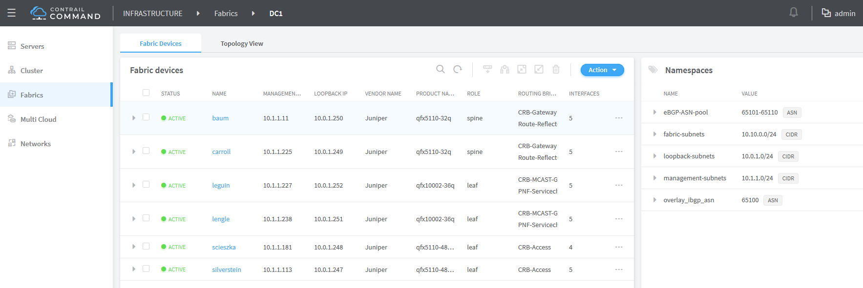
Table 1 shows the routing and bridging roles that are available for each of the physical roles.
Physical Role |
Routing Bridging Role |
Description |
|---|---|---|
Spine |
Route-Reflector |
Specifies that the device acts as a route reflector for IBGP to satisfy the full-mesh requirement and enable scalability for the fabric. Usually all spine devices or gateways are given this role. |
Null |
Specifies that the device is used in an IP routing environment that provides only underlay routing; does not participate in VXLAN tunnels. Applies only to spine devices when edge routing and bridging is used |
|
CRB-Gateway |
Provides Layer 3 Unicast gateway functionality for routing between VNIs using an IRB interface. Routing is done centrally on a spine |
|
CRB-MCAST-Gateway |
Provides Layer 3 multicast gateway for routing between VNIs using an IRB interface. Multicast routing is done centrally. It is not supported on QFX5100 and 5200 hardware families. |
|
DC-Gateway |
Provides a routing connection for traffic to exit the data center Devices that provide connectivity to external networks or between fabrics. |
|
DCI-Gateway |
Interconnects a logical router in one data center to a logical router in a different data center using EVPN VXLAN Type 5 routes. |
|
PNF-Servicechain |
Specifies the devices where the Layer 3 PNF is attached. |
|
AR-Replicator |
Specifies that the device eplicates BUM traffic from one overlay tunnel to others. |
|
AR-Client |
Specifies that the device sends BUM traffic to an AR replicator. |
|
Leaf |
CRB-Access |
Specifies devices in a CRB architecture that perform only Layer 2 VXLAN functionality (bridging). |
ERB-UCAST-Gateway |
Specifies that routing occurs at the leaf switch. IRB interfaces are configured at the leaf switch to enable unicast traffic routing. While unicast traffic can be routed at the leaf switches, multicast traffic routing still occurs at the spine devices. In contrast, the CRB-Gateway role at a spine is capable of routing both unicast and multicast traffic. With ERB, leaf switches route the unicast traffic, which makes the configuration of the CRB-Gateway role on the spine unnecessary since unicast traffic will never be routed to a spine device. Instead, you must configure the spine devices with the CRB-MCAST-Gateway role to route multicast traffic when required. |
|
CRB-MCAST-Gateway |
Provides Layer 3 multicast gateway for routing between VNIs using an IRB interface. Multicast routing is done centrally. It is not supported on QFX5100 and 5200 hardware families. |
|
Route-Reflector |
Specifies that the device acts as a route reflector for IBGP to satisfy the full-mesh requirement and enable scalability for the fabric. Usually all spine devices or gateways are given this role. |
|
DCI-Gateway |
Interconnects a logical router from one data center to another by using EVPN VXLAN Type 5 routes. This role should be configured on all border leafs. |
|
PNF-Servicechain |
Specifies the devices where the Layer 3 PNF is attached. |
|
AR-Replicator |
Specifies that the device replicates BUM traffic from one overlay tunnel to others. |
|
AR-Client |
Specifies that the device sends BUM traffic to an AR replicator. |
|
PNF |
PNF-Servicechain |
Specifies the devices where the Layer 3 PNF is attached. |
See Also
Virtual Networks
A virtual network is a bridge domain or LAN segment. It can be associated to a subnet (prefix of hosts attached to the LAN segment), similarly to hosts connected to a LAN switch in a building. You create LAN segments to give departments, or tenants, access to servers that are spread across the VXLAN network.
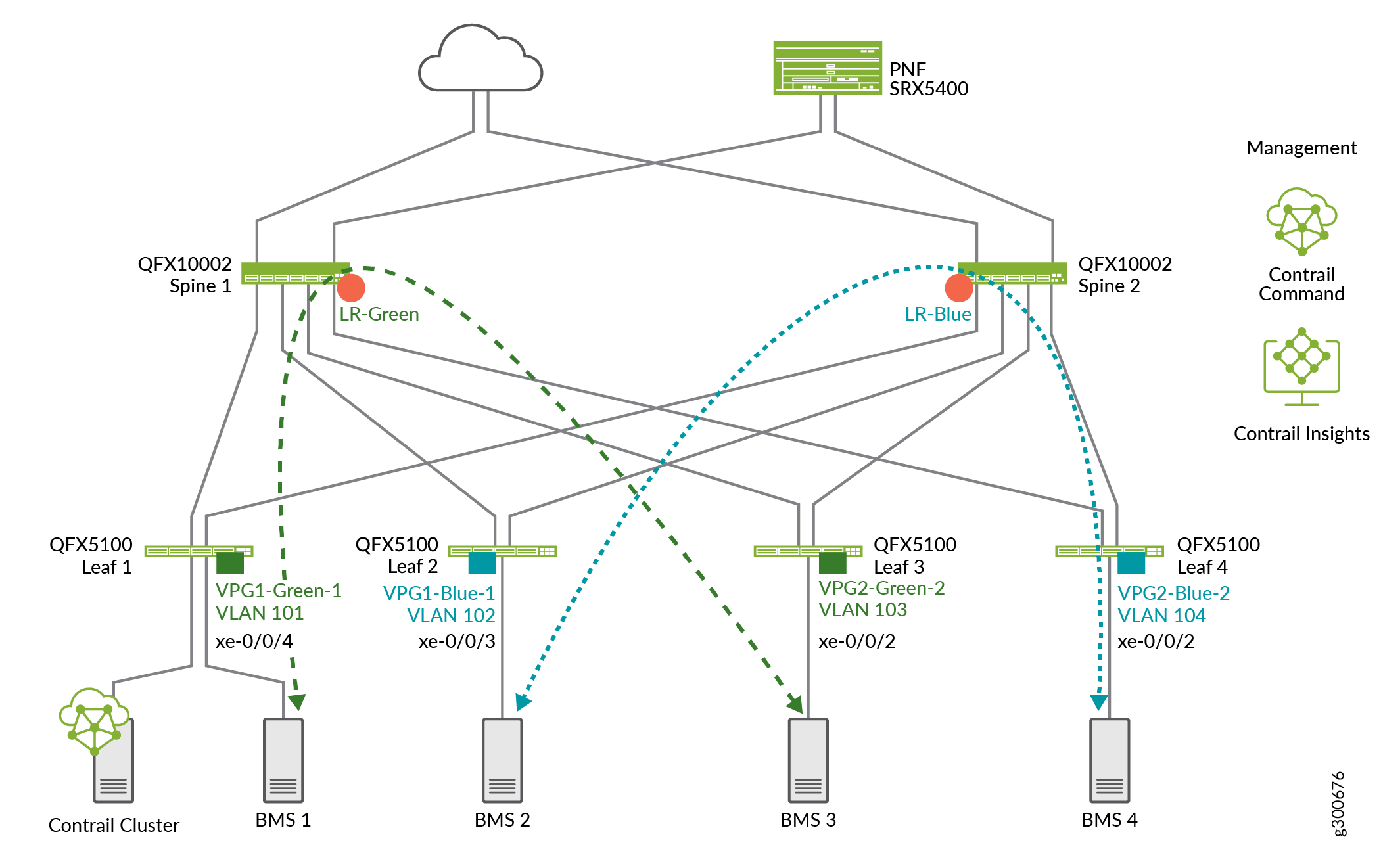
To do so, you specify which servers are on the same VLAN or VNI and allow them to reach each other over VXLAN tunnels across the fabric. In this example shown in Figure 2, BMS 1and BMS 3 servers have been added to the Green virtual network so they can reach each other. BMS 2 and BMS 4 have been added to the blue virtual network.

See Also
Virtual Port Groups
VPG provides connectivity to servers that were not configured by Contrail Command. A virtual port group (VPG) is the representation of:
A group of one or more physical interfaces (or ports) on one or more physical devices, and
How these ports are used as server attachment points to the VXLAN virtual networks (VLANs)
Each VPG is assigned VXLAN Network Identifier (VNI) and is attached to a virtual network. You can select multiple interfaces on the same device or on different devices. A VPG is similar to a link aggregation group (LAG) but supports both LAG and multihoming depending on whether you select the interfaces on the same devices or on different devices. A LAG is automatically created if you select more than one interface on the same device.
When you provision a VPG, you can define a Security Group, which corresponds to a 5-tuple stateless filter or ACL, or which advanced port profile (such as for storm control) is applied on the access VLANs of this VPG.
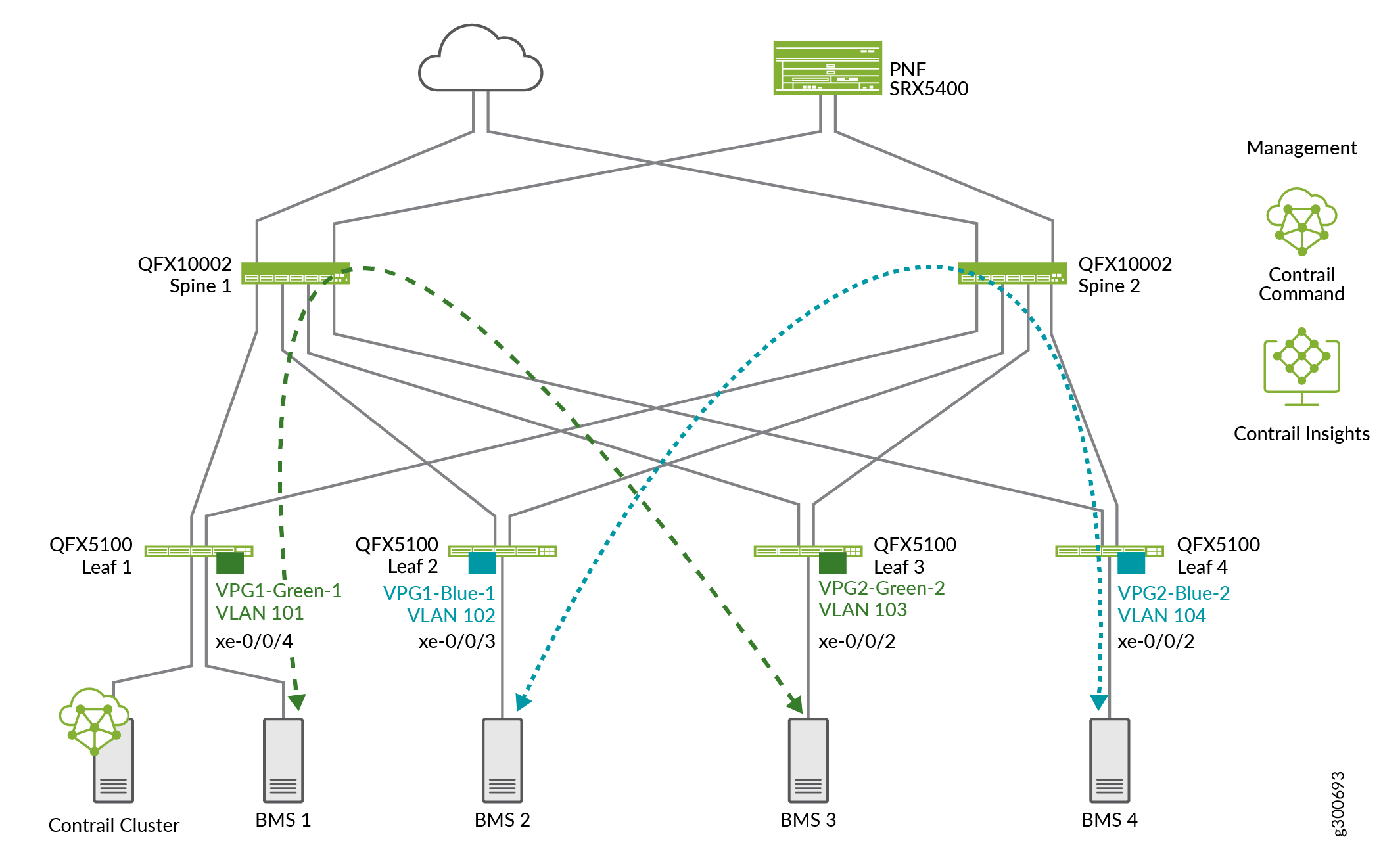
Figure 3 show VPGs attached to leaf devices for each end of the green and blue virtual networks.
See Also
Logical Routers
In CEM a logical router is a Layer 3 virtual routing and forwarding (VRF) routing instance for a tenant that provides routed connectivity for devices in the same virtual network. The logical router represents a Layer 3 routing table and its attachment points to the Layer 2 tenant network.
In the Layer 3 routing instance, there is one IRB unit for each virtual network that is attached to the logical router. These IRBs correspond to the anycast gateway of the virtual network to which any unknown traffic is sent. Traffic from a virtual network (a Layer 2 bridge domain) that has to reach a subnet for which it doesn’t have an explicit route Is sent to the IRB.
Figure 4 shows logical routers added to spines for the green and blue virtual networks shown in the previous section.