Contrail SD-WAN Deployment Architectures
An SD–WAN implementation offers a flexible and automated way to route traffic from site to site. As shown in Figure 1, a basic SD–WAN architecture includes just a few basic elements
Multiple sites
Multiple connections between sites that form the underlay network
Multiple overlay tunnels
A controller
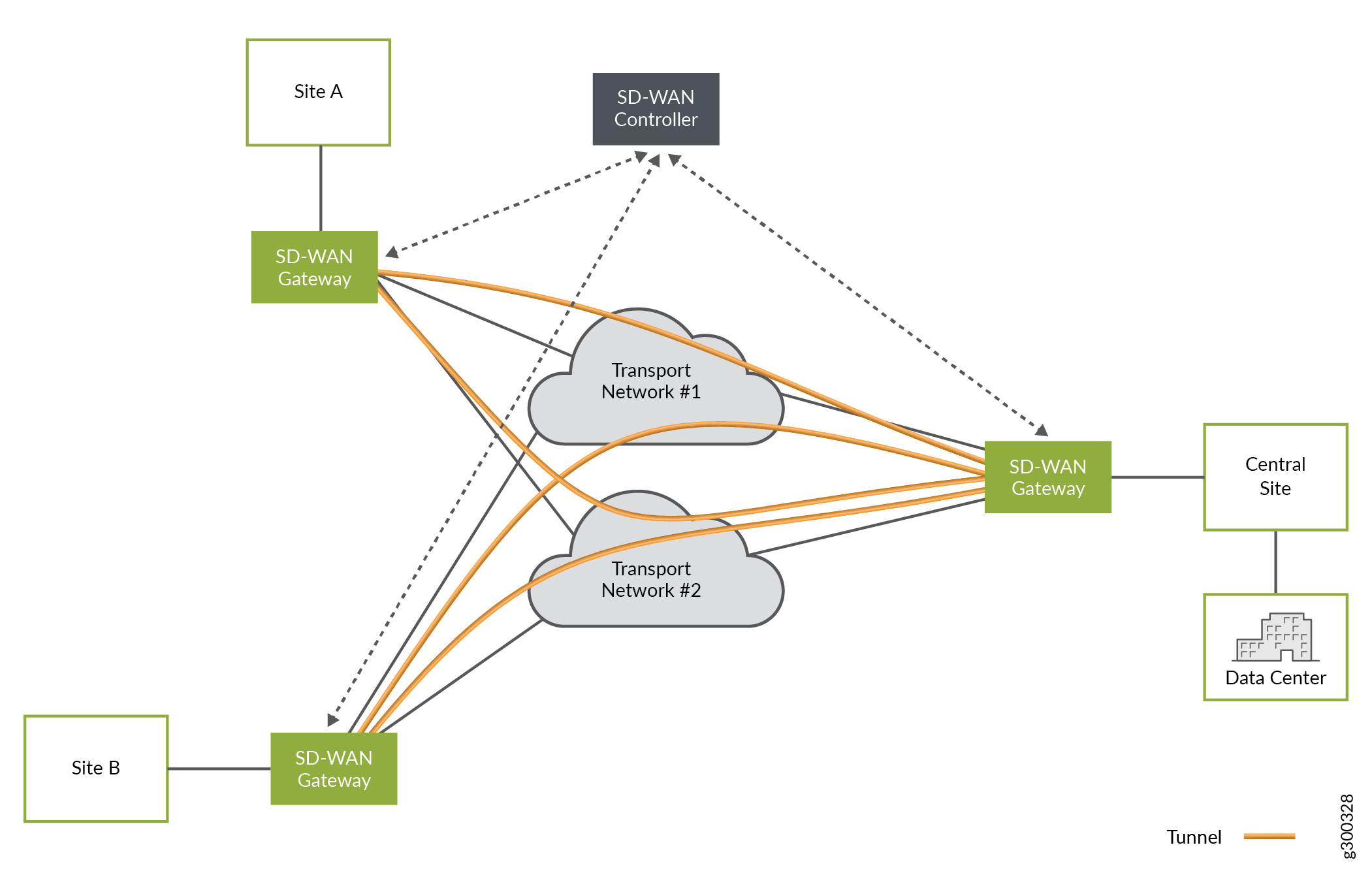
The SD–WAN controller, built in to CSO, acts as an orchestration layer and provides an interface, allowing the operator to setup and manage the devices at the sites.
Contrail SD-WAN Reference Architecture
Juniper Networks Contrail SD–WAN solution architecture, shown in Figure 2 uses a hub–and–spoke topology , with CPE devices located at customer branch sites. On the local side of the site, the CPE devices connect to LAN segments and participate in dynamic routing protocols with other LAN devices. On the WAN side, the CPE devices connect across two or more links to a provider hub device. Because the SD-WAN model uses a hub–and–spoke topology, traffic travels from site to site through the provider hub. By default, traffic going to the Internet also flows through the provider hub device.

The SD-WAN orchestrator and controller functions are implemented through Juniper Networks Contrail Service Orchestration (CSO) software. The CSO platform uses policies and SLA parameters to differentiate and direct traffic flows across the available paths as desired.
The following sections describe these architectural elements in more detail.
Spoke Devices
The CPE device at an enterprise customer’s branch site acts as a spoke device in the SD-WAN model. The device also acts as a gateway router , providing connectivity from the branch site to other sites in the tenant network and to the Internet. There are two types of spoke devices: on-premises spoke and cloud spoke.
On-Premises Spoke Devices
On–premises spoke devices can be either NFX Series devices or specific SRX Series Firewalls.
NFX Series Network Services Platform
An NFX Series Network Services Platform used as an on-premises spoke device can host a range of multivendor VNFs, support service chaining, and be managed by orchestration software in the cloud. NFX Series devices eliminate the operational complexities of deploying multiple physical network devices at a customer site and offer a substantial improvement over traditional, single function CPE devices.
A key VNF supported on the NFX Series platform is the vSRX Virtual Firewall Virtual Firewall. In the Contrail SD–WAN solution, the vSRX Virtual Firewall instance with routing and switching capabilities performs the gateway router function. It also provides the same feature-rich security services found on standard SRX Series Firewalls. Table 1 shows the NFX Series hardware that you can implement as an on-premises spoke device.
The NFX150 features a built–in SRX firewall in place of the vSRX Virtual Firewall functionality found on other NFX Series devices.
Platform |
Models Supported |
|---|---|
NFX150 Network Services Platform |
|
NFX250 Network Services Platform |
|
SRX Series Devices and vSRX Virtual Firewall Virtual Firewalls
A physical SRX Series security device can be used in place of the NFX Series platform to provide the gateway router function, as can a vSRX Virtual Firewall instance installed on a server. Table 2 shows the SRX hardware and vSRX Virtual Firewall virtual firewalls that you can implement as on-premises spoke devices.
Platform |
Models Supported |
|---|---|
SRX Series |
|
vSRX Virtual Firewall Virtual Firewalls |
vSRX Virtual Firewall vSRX Virtual Firewall 3.0 |
For the most up to date information on hardware and software support for CSO, see the Contrail Service Orchestration Release Notes.
Cloud Spoke Devices
A Contrail SD–WAN cloud spoke device, in the form of a vSRX Virtual Firewall, can be located in an AWS VPC. The vSRX Virtual Firewall serves as a spoke device in the cloud; once the endpoint comes online, it acts like any other spoke device.
Spoke Redundancy
Two redundant CPE devices can be used at spoke sites to protect against device and link failures. For more detail, see the Resiliency and High Availability section. of the Contrail SD-WAN Design and Architecture Guide.
Provider Hub Devices
The Contrail SD–WAN solution supports two deployment topologies (discussed later in this guide): dynamic mesh and hub-and-spoke. In a dynamic mesh deployment, each site has a CPE device that connects to the other sites and the enterprise hub device. In a hub-and-spoke deployment, there is at least one provider hub device and one or more spoke devices.
The provider hub device terminates both MPLS/GRE and IPsec tunnels from spoke devices.
Provider Hubs
In a service provider (SP) environment, the service provider hosts a provider hub device in their network. The provider hub device acts as a point of presence (POP) or connection point. It is typically a shared device, providing hub functionality to multiple customers (tenants) through the use of virtual routing and forwarding instances (VRF). The SP administrator and the OpCo administrator can both manage the provider hub device.For CSOaaS, the SP administrator role is performed by Juniper Networks as the cspadmin user (or equivalent). The OpCo administrator role can be assigned to a user by the SP administrator, but the OpCo administrator does not have SP administrator privileges.Table 3 lists the provider hub devices supported in a CSO SD-WAN environment.
Role |
Supported Device Types |
|---|---|
Provider Hub |
|
For the most up to date information on hardware and software support for CSO, see the Contrail Service Orchestration Release Notes.
Provider Hub Redundancy
Two redundant provider hub devices can be used at one POP to protect against device and link failures, and to provide upstream multi-homing for spoke sites. For more detail, see the Resiliency and High Availability topic in this guide.
Enterprise Hub Sites and Devices
A special type of spoke device, called an enterprise hub device, can be deployed as the CPE at an on-premises spoke site. SRX1500, SRX4100, and SRX4200 devices can serve this function. The spoke site that functions this way, must be configured as an enterprise hub site during site creation. Creating an enterprise hub site opens additional functionality for the site:
Can act as the anchor point for site–to–site communications on the customer’s network.
Can act as the central breakout node for the customer’s network.
Offers a specialized department called the data–center department.
Supports data center dynamic LAN segments with BGP and OSPF route imports, including default routes, from the LAN–side Layer 3 device.
Allows for intent-based breakout profiles to create granular breakout behavior based on department, application, site, and so on.
In an enterprise environment, the enterprise hub is owned by the customer (tenant) and usually resides within an enterprise data center. Only the customer’s spoke sites can connect to the enterprise hub device. OpCo administrators and tenant administrators can manage the enterprise hub. Table 4 lists the enterprise hub devices supported in a CSO SD-WAN environment.
Role |
Supported Device Types |
|---|---|
Enterprise Hub |
|
For the most up to date information on hardware and software support for CSO, see the Contrail Service Orchestration Release Notes.
Underlay (Physical) Network
The underlay network includes the physical connectivity between devices in the SD–WAN environment. This layer of the network has no awareness of the customer LAN segments, it simply provides reachability between on-premises devices.
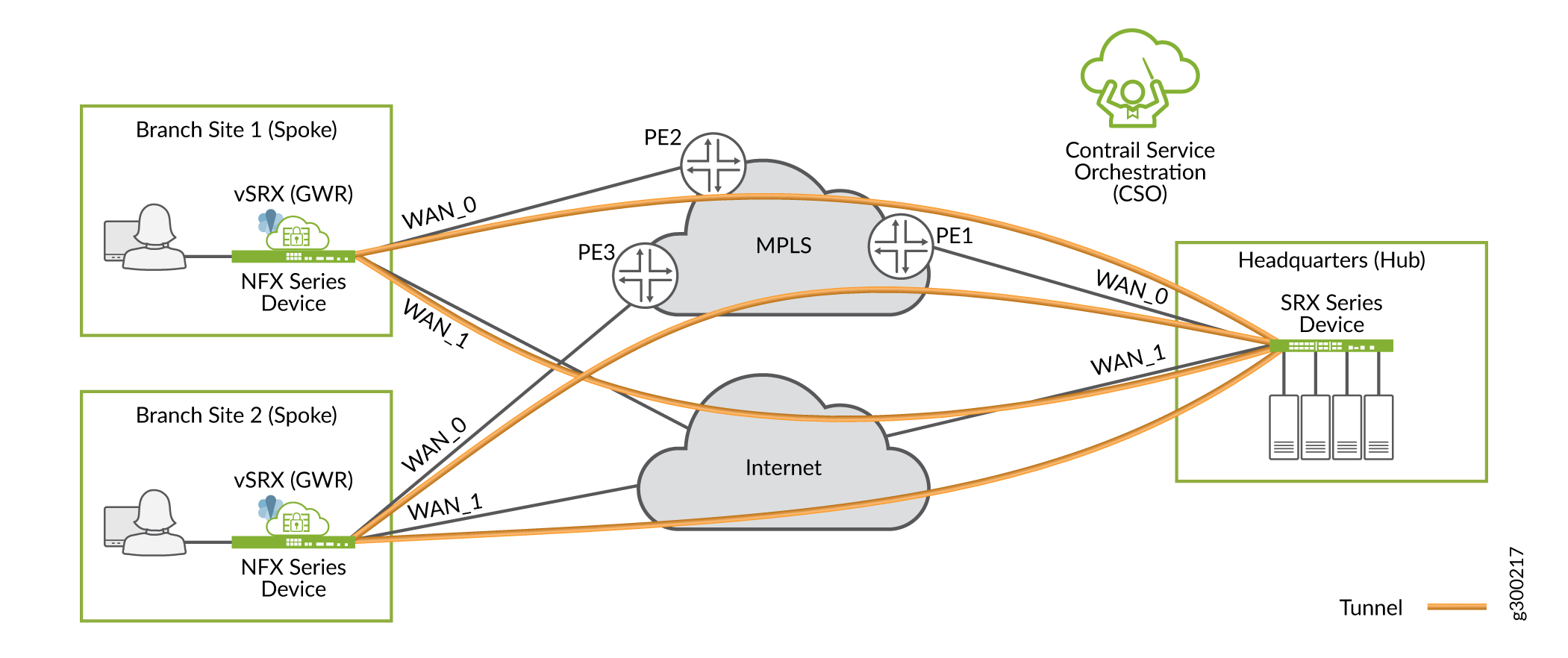
Figure 3 shows a sample underlay network for a hub–and–spoke SD–WAN deployment (the details apply equally to a dynamic mesh setup). Each spoke site typically has multiple paths to the hub site; in this case, one through the private MPLS cloud, and one over the Internet.

Each on-premises device (or site) can have up to four WAN links, including a satellite link that can be used for OAM. During configuration, CSO identifies the devices’ WAN–facing interfaces as WAN_0 through WAN_3.
Note that:
The WAN interfaces can be VLAN tagged or untagged, as per design requirements.
The on-premises devices’ Internet-facing interfaces can be attached to different service provider networks.
WAN Access Options
Each WAN access type listed below can be used for ZTP, data, or OAM traffic. All the links can be leveraged for data traffic simultaneously.
MPLS
Ethernet
LTE
Note:LTE WAN access supported using a dongle on NFX250 Series devices.
LTE WAN access supported using a built-in interface on NFX150 Series devices.
LTE WAN access supported using a mini–PIM in slot 1 of SRX300 Series devices.
All of the previously mentioned LTE interfaces are supported for ZTP.
Only supported for Hub–and–Spoke SD–WAN deployments with single CPE.
Full-cone and restrictive NAT deployments are supported.
Dual CPE configurations are not supported.
LTE APN settings can be localized for the installation region during the ZTP process.
ADSL/VDSL (ADSL/VDSL support for WAN links and ZTP on NFX Series devices starting in CSO Release 4.0.0, and ADSL support on the SRX300 Line of Services Gateways starting in CSO Release 5.2.0.)
Broadband
MPLS and broadband
Satellite link
WAN Interface Types - Data and OAM
The WAN interfaces are used primarily to send and receive user traffic (data). At least one of the WAN interfaces must also be used for management (OAM) traffic. The OAM interface is used to communicate with CSO, and allows CSO to manage the on-premises device.
Figure 4 illustrates these two interface types.
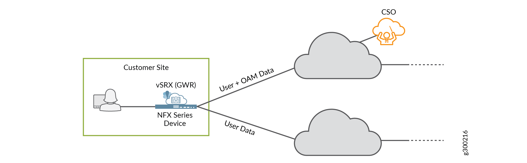
Note that:
The on-premises device’s OAM interface must be able to reach CSO. The connectivity can be supplied strictly using CSO-orchestrated overlay networks. You do not need pre–existing underlay network connectivity for this. Starting in CSO release 5.0.1, CSO automatically selects an IP address for the on-premises device’s OAM interface. This ensures that the address is unique within the entire CSO deployment and prevents human error.
To ensure secure communication over the WAN, the on-premises device initiates the connection to CSO.
Device–initiated connections can work across intermediate NAT devices.
The user-and-OAM-data interface can use a single IP address for both functions.
Overlay (Tunnels) Network
The overlay network includes the logical tunnel connectivity between devices in the SD–WAN environment. This layer of the network has awareness of the customer LAN segments, and is responsible for transporting customer traffic between sites.
Figure 5 shows an overlay network for a hub–and–spoke environment. Each spoke site has two tunnels to carry traffic to the hub site: one through the private MPLS cloud, and one over the Internet.
The tunnels have two encapsulation options: MPLSoGRE or MPLSoGREoIPsec. CSO automatically provisions and establishes these tunnels as part of the deployment process.
Overlay Deployment Topologies
The SD–WAN solution supports hub–and–spoke or dynamic mesh deployment topologies. A dynamic mesh topology is similar to a full mesh topology wherein every site is capable of connecting directly to any other site. But with dynamic mesh, the connections (tunnels) are brought up on-demand, thereby reducing the continual load on any one site. A single tenant can support both hub-and-spoke and dynamic mesh topologies.
Hub and Spoke
With the hub–and–spoke topology, all spoke sites are connected to at least one hub site, as shown in Figure 6. Spoke sites cannot communicate directly with other spoke sites.
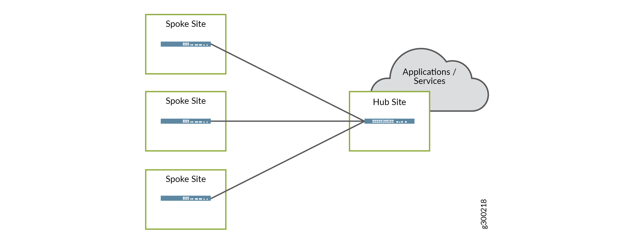
The hub sites used can be either provider hub or enterprise hub sites. When an enterprise hub site is used, the provider hub (if any) is used as backup only. This topology is preferred when applications and services are centralized at the hub site.
Dynamic Mesh
With the dynamic mesh topology, overlay tunnels between participating sites enable the sites to communicate directly with each other, as shown in Figure 7. Although the figure shows the DATA_AND_OAM connection on the MPLS link, WAN_0, this function can be performed on either the MPLS or Internet links.
This topology is well suited for deployments where applications and services are not centralized.
Both hub–and–spoke and full mesh topologies require adding a secure OAM network overlay, and thus an OAM Hub, to the deployment.
When spoke devices are added to a dynamic mesh topology, the administrator configuring the sites must assign a mesh tag to each WAN interface. Only two devices with matching mesh tags can form the VPN connection to allow communication. Interfaces with mismatched mesh tags can never communicate directly.
Orchestration and Control
Orchestration and controller functions are implemented through Juniper’s Contrail Service Orchestration (CSO) software. As shown in Figure 8, CSO software offers a Web–based UI to manage the SD-WAN environment. Figure 8 is a sample image and the CSO version number on it is only for reference.

The Service Orchestration Layer contains the Network Service Orchestrator (NSO). The orchestration software has a global view of all resources and enables tenant management, providing end–to–end traffic orchestration, visibility, and monitoring. The Domain Orchestration Layer contains the Network Service Controller (NSC). The orchestration software works together with the controller to manage on-premises (CPE) devices, and provide topology and CPE lifecycle management functionality.
At the user level, CSO provides the interface to deploy, manage, and monitor the devices in the SD–WAN network through the NSC. At the network level, NSC includes a vRR that allows each site to advertise its local routes to remote sites.
Secure OAM Network
SD–WAN deployments include a secure OAM overlay network to provide end-to-end secure communications between on-premises devices and CSO. For CSOaaS, this is automatically provided as part of the service.
As shown in Figure 9, dedicated, IPsec-encrypted OAM tunnels enable on-premises devices to send management, routing, and logging traffic securely over the network to a provider hub. The provider hub then forwards the traffic to CSO.

- Integration with Deployment Topologies
- OAM Hub Design Options
- Usage Notes on Provider Hub Design Options
Integration with Deployment Topologies
Both the hub–and–spoke and dynamic mesh deployment topologies must use secure OAM tunnels.
Hub and Spoke
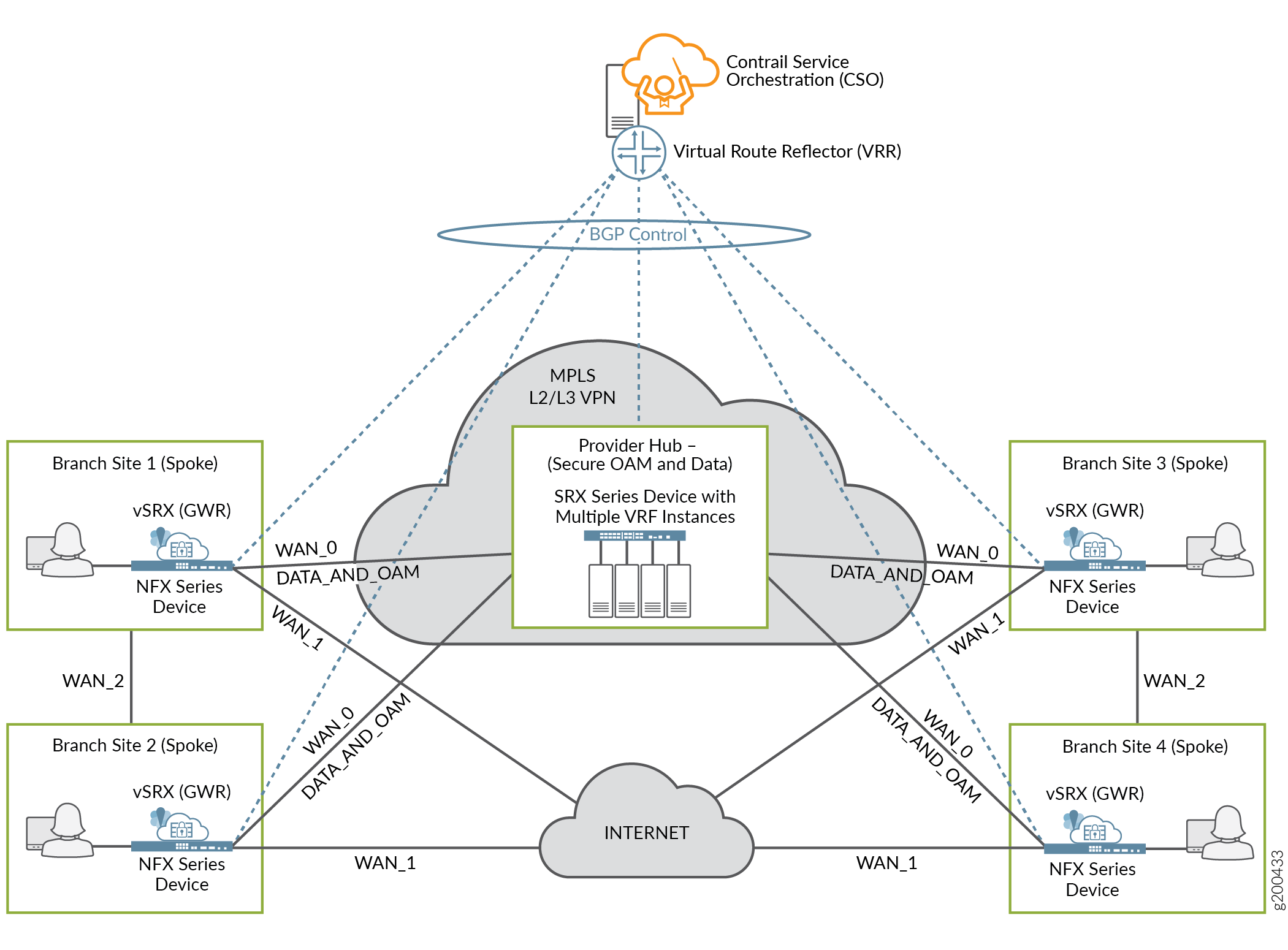
With the hub–and–spoke topology, each spoke site now has two sets of connections to the provider hub site: an overlay tunnel carrying data, and a separate, dedicated IPsec overlay tunnel carrying OAM traffic, as shown in Figure 10.

Dynamic Mesh
Since a normal full mesh topology would not include a hub device for data traffic, one must be added. As shown in Figure 11, each spoke site has a new connection: a separate, dedicated IPsec overlay tunnel carrying OAM traffic to the provider hub.

OAM Hub Design Options
There are two ways to implement the OAM hub in an on–premises CSO deployment, depending on design requirements. As shown in Figure 12, the options are as follows:
Data and OAM tunnels terminate on same provider hub device—This is a good option for small deployments, where the single hub device can handle both the data and OAM traffic.
Data and OAM tunnels terminate on separate provider hub devices—This option can be useful for larger deployments where the main hub device’s resources are needed to service the overlay tunnels carrying data traffic; a second hub device can be used to terminate the OAM tunnels.
Figure 12: OAM Tunnels - Provider Hub Design Options
For CSOaaS, the OAM hub is provided as part of the service.
However, an OpCo administrator can deploy a DATA_ONLY or an OAM_AND_DATA hub. In the case of a DATA_ONLY hub, the DATA hub has an IPsec secured tunnel to the OAM_HUB. In the case of an OAM_AND_DATA hub, the OpCo administrator is required to set up the IPsec secured connection between the OAM_AND_DATA HUB and CSO.
Usage Notes on Provider Hub Design Options
An OAM hub can support multiple tenants, or can be dedicated to a single tenant.
Connectivity from the provider hub(s) to CSO should be private and secured, as it is not covered by the OAM tunnels.
We recommended that you implement multiple OAM hubs for redundancy and to ensure no loss of management or monitoring of the on-premises devices.
For CSOaaS, OAM hub redundancy is part of the service.
When a spoke site is multi-homed to multiple hub devices, one OAM tunnel should terminate on each hub.
On-premises devices using NAT are supported for hub-and-spoke deployments.
Zero Touch Provisioning
One of the key features of the Contrail SD–WAN solution is the ability to “plug–and–play” new spoke devices using ZTP (autoinstallation). The following is a high-level list of steps performed during ZTP:
If you implement the on-premises version of CSO, you need to add the appropriate CSO SSL certificate to the redirect server before performing ZTP.
Note:If you deploy the cloud-delivered version of CSO, Juniper Networks configures the redirect server for you.
When a spoke device first comes online, it uses a local DHCP server to obtain an IP address and name server information.
The spoke device then contacts the redirect server, which provides the DNS name and certificate for the CSO installation.
The spoke device then contacts the CSO server to obtain its initial configuration and Junos OS software update (if required).
CSO Release 4.1 and later include enhancements that reduce the bandwidth required for ZTP to 2 Mbps.
Usage Notes for ZTP
At least one of the device’s WAN interfaces must obtain its IP address from a DHCP server in order to also be assigned a DNS name server and a default route.
Both CSO and the redirect server must be reachable over the same WAN interface.
The ZTP process can be run from any WAN interface on the spoke device, including a satellite link.
The download of the initial configuration can require significant amount of time, especially on slow links, due to the size of configuration and Junos OS software.
Redirect Server
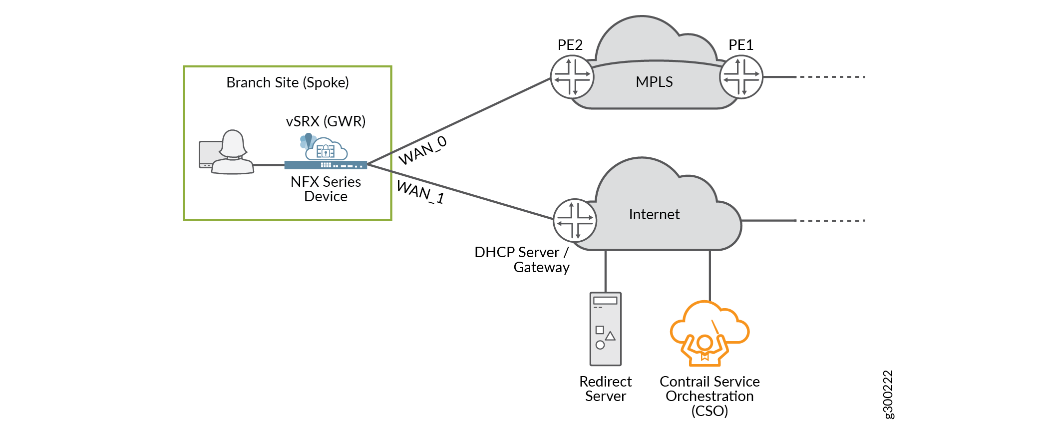
The redirect server is an Internet–located, Juniper–owned–and–managed server that is integral to the ZTP process. The server enables each spoke device to locate and authenticate with its designated CSO instance. With the assistance of the redirect server, the spoke device can contact CSO and receive its initial configuration, including a Junos OS software update (if required).
For on-premises deployments of CSO, the administrator configures WAN ports on the spoke devices to connect to both the Internet and the redirect server. For cloud-delivered CSO, Juniper Networks handles this configuration for you.
In Figure 13, both the redirect server and CSO are located on the Internet. The spoke device obtains and uses IP addressing and other information provided through its Internet–facing interface, and can reach both the redirect server and CSO through that same WAN interface.
Service Chaining in Contrail SD-WAN
Starting in CSO Release 4.0, service chaining is available for SD-WAN environments. Service chaining is a concept wherein multiple network services instantiated in software and running on x86 hardware are linked, or chained together in an end-to-end fashion. This allows the one physical device to provide the services normally provided by multiple devices. Service chaining can be performed on NFX Series devices, as shown in Figure 14.
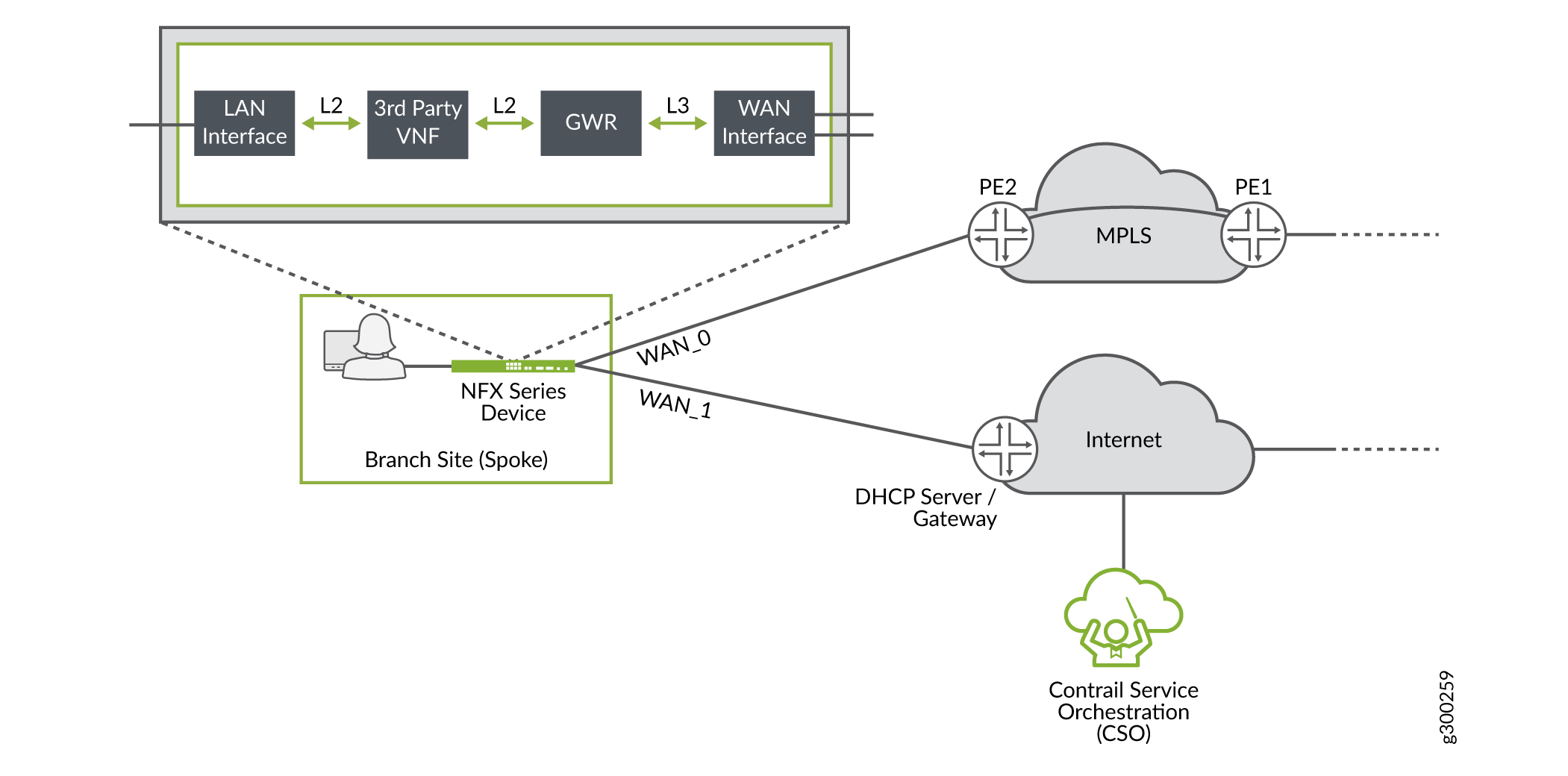
Starting in CSO Release 4.0, the following third-party virtual network functions (VNFs) are supported: Fortigate-VM and Single-legged Ubuntu VM.
Currently only Layer 2 VNF mode is supported in SD-WAN service chains.
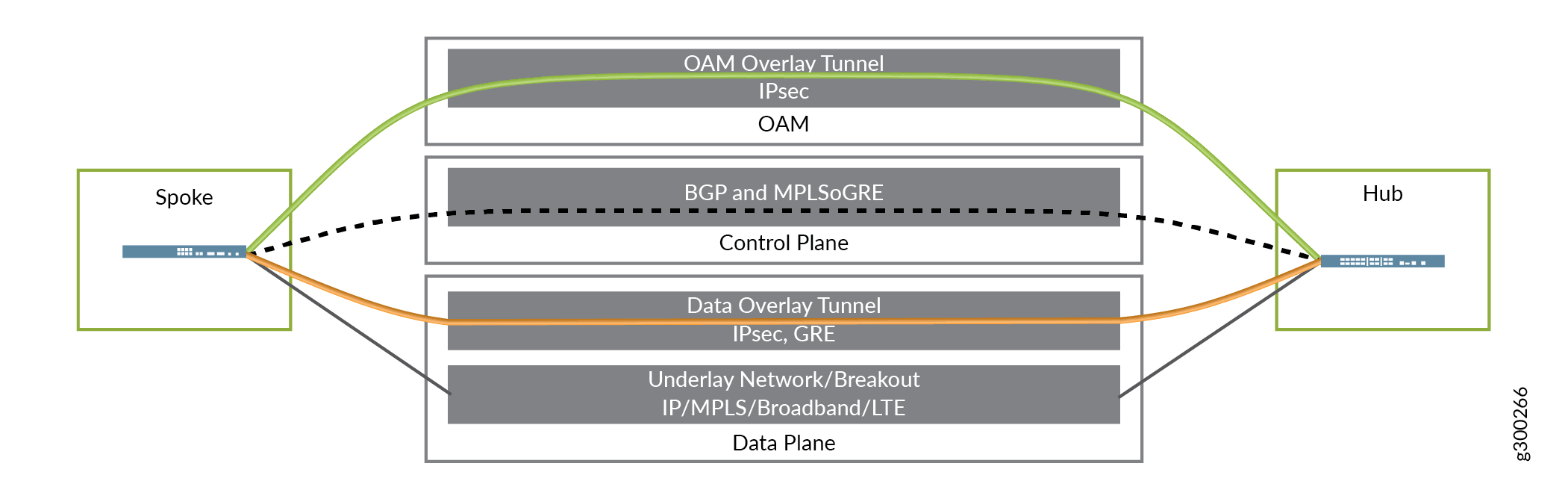
Three Planes, Four Layers
To bring all of the above elements together, the Contrail SD–WAN Architecture can be thought of in three planes, comprised of four functional layers:
Data Plane:
Includes the underlay network; provides physical connectivity
Includes the overlay network; provides tunnels for tenant data traffic
Control Plane—Includes the routing protocols which flow through the OAM tunnels
Management Plane—Includes the overlay tunnels for the secure OAM network
Figure 15 illustrates this concept.
Change History Table
Feature support is determined by the platform and release you are using. Use Feature Explorer to determine if a feature is supported on your platform.