Help us improve your experience.

Let us know what you think.

Do you have time for a two-minute survey?

Announcement: Try the Ask AI chatbot for answers to your technical questions about Juniper products and solutions.

close
header-navigation
keyboard_arrow_up
list Table of Contents
file_download PDF
{ "lLangCode": "en", "lName": "English", "lCountryCode": "us", "transcode": "en_US" }
English
keyboard_arrow_right

EVPN-VXLAN for AI-ML Data Centers

date_range 20-Dec-24

Overview of EVPN-VXLAN for AI-ML Data Centers

This document covers the steps necessary to configure Ethernet VPN-Virtual Extensible LAN (EVPN-VXLAN) in an artificial intelligence (AI) and machine learning (ML) data center fabric.

Features and Benefits of an AI-ML Data Center

  • Improve scalability: You can enable multitenancy within the same data center using an IP fabric overlay.

  • Improve productivity: You can run different AI workloads (multiple large language models (LLMs) for different tenants) in the same data center.

  • Improve security: You can isolate L2 at the local top-of-rack (ToR) level with multiple MAC-VRF instances, or L3 at the ToR level with multiple EVPN Type 5 routing instances (IP-VRF-to-IP-VRF model). See the configuration section for examples of these use cases.

  • Reduce configuration efforts: You can extend the tenants' logical context between different ToR switches in different points of delivery (PODs) without changing the configuration of the intermediate spine or superspine devices.

Configuration

Configuration Overview

We'll look at two use cases relevant to this topic. The first use case is running two MAC-VRF instances on the same device in a data center. The second use case is running two EVPN Type 5 VRF instances on the same device in a data center.

Use Case #1: Two MAC-VRF instances on the same device:

  • Separate MAC-VRF instances help to isolate the AI data center tenants at the L2 level, and extend this isolation using the EVPN-VXLAN overlay.

  • The intermediate AI data center spine and superspine devices don't require provisioning each new AI data center tenant.

  • The L2 connectivity is closer to the actual service connection.

  • AI data center tenants can be in the same MAC-VRF L2 EVPN instance (EVI) when you configure the tenants with the vlan-aware EVPN service type.

Use Case #2: Two EVPN Type 5 IP-VRF instances on the same device:

  • Multiple EVPN Type 5 routing instances can isolate the AI data center tenants at the L3 routing level. Pure Type 5 routing can also extend the context within a POD or between PODs.

  • EVPN signaling exchanges between the ToR switches of the AI data center automatically establish VXLAN tunnels for Type 5 routes.
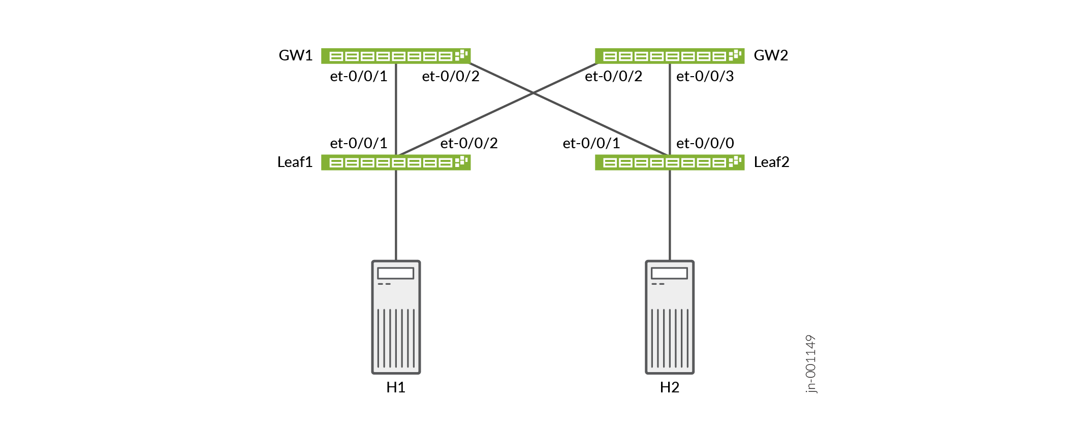
Topology

The topology for these examples uses QFX5240-64QD switches for both the spine and leaf layers. The network is an edge-routed bridging (ERB) architecture.

How to Configure Two MAC-VRFs

Use the following steps as a guide to configure two MAC-VRF instances on the same leaf node. We use actual values for example purposes. You should customize these steps with relevant values for your implementation.
  1. Configure a MAC-VRF routing instance.
    content_copy zoom_out_map
    set routing-instances myMACVRF101 instance-type mac-vrf
  2. Configure the EVPN protocol with VXLAN encapsulation and supporting statements.
    content_copy zoom_out_map
    set routing-instances myMACVRF101 protocols evpn encapsulation vxlan
    set routing-instances myMACVRF101 protocols evpn default-gateway no-gateway-community
    set routing-instances myMACVRF101 protocols evpn extended-vni-list 5101
  3. Configure a virtual tunnel endpoint (VTEP) interface.
    content_copy zoom_out_map
    set routing-instances myMACVRF101 vtep-source-interface lo0.0
  4. Configure a service type. We use vlan-aware for this example. vlan-aware allows configuring more than one VLAN.
    content_copy zoom_out_map
    set routing-instances myMACVRF101 service-type vlan-aware
  5. Configure an interface for the routing instance.
    content_copy zoom_out_map
    set routing-instances myMACVRF101 interface et-0/0/4.0
  6. Configure a route distinguisher (RD) and a VRF target.
    content_copy zoom_out_map
    set routing-instances myMACVRF101 route-distinguisher 10.203.113.10:101
    set routing-instances myMACVRF101 vrf-target target:1:9101
  7. Configure one or more VLANs.
    content_copy zoom_out_map
    set routing-instances myMACVRF101 vlans vlan101 vlan-id 101
    set routing-instances myMACVRF101 vlans vlan101 l3-interface irb.101
    set routing-instances myMACVRF101 vlans vlan101 vxlan vni 5101
  8. Configure a second MAC-VRF routing instance. The full configuration is displayed. Note the differences in VLANs, RD, VRF-target, and interfaces. This routing instance uses the vlan-based service type, limiting the configuration to a single VLAN. Either vlan-based or vlan-aware are valid choices.
    content_copy zoom_out_map
    set routing-instances myMACVRF102 instance-type mac-vrf
    set routing-instances myMACVRF102 protocols evpn encapsulation vxlan
    set routing-instances myMACVRF102 protocols evpn default-gateway no-gateway-community
    set routing-instances myMACVRF102 protocols evpn extended-vni-list 5102
    set routing-instances myMACVRF102 vtep-source-interface lo0.0
    set routing-instances myMACVRF102 service-type vlan-based
    set routing-instances myMACVRF102 interface et-0/0/5.0
    set routing-instances myMACVRF102 route-distinguisher 10.203.113.10:102
    set routing-instances myMACVRF102 vrf-target target:1:9102
    set routing-instances myMACVRF102 vlans vlan102 vlan-id 102
    set routing-instances myMACVRF102 vlans vlan102 l3-interface irb.102
    set routing-instances myMACVRF102 vlans vlan102 vxlan vni 5102

Verification

Verify that routing is working as expected. Note that verification requires other network devices to be configured, and your outputs will vary.
content_copy zoom_out_map
user@device> show route table myMACVRF101.evpn.0 active-path 

myMACVRF101.evpn.0: 10 destinations, 15 routes (10 active, 0 holddown, 0 hidden)
+ = Active Route, - = Last Active, * = Both

2:10.203.113.10:101::5101::00:10:94:00:00:05/304 MAC/IP        
                   *[EVPN/170] 04:43:28
                       Indirect
2:10.203.113.10:101::5101::6c:62:fe:b9:3b:3d/304 MAC/IP        
                   *[EVPN/170] 05:23:00
                       Indirect
2:10.203.113.11:101::5101::00:10:94:00:00:06/304 MAC/IP        
                   *[BGP/170] 04:36:14, localpref 100, from 10.203.113.14
                      AS path: 65101 64513 I, validation-state: unverified
                       to 192.0.2.11 via et-0/0/1.0, Push 5101
                       to 192.0.2.9 via et-0/0/0.0, Push 5101
                    >  to 192.0.2.13 via et-0/0/2.0, Push 5101
2:10.203.113.11:101::5101::6c:62:fe:b9:22:3d/304 MAC/IP        
                   *[BGP/170] 04:36:26, localpref 100, from 10.203.113.13
                      AS path: 65101 64513 I, validation-state: unverified
                       to 192.0.2.11 via et-0/0/1.0, Push 5101
                       to 192.0.2.9 via et-0/0/0.0, Push 5101
                    >  to 192.0.2.13 via et-0/0/2.0, Push 5101
content_copy zoom_out_map
user@device> show mac-vrf forwarding vlans      

Routing instance        VLAN name             Tag          Interfaces
default-switch          default               1        
                                                            
myMACVRF101             vlan101               101      
                                                           et-0/0/4.0*
                                                           vtep-53.32773*
myMACVRF102             vlan102               102      
                                                           et-0/0/5.0
                                                           vtep-54.32773*
content_copy zoom_out_map
user@device> show ethernet-switching table vlan-id 101  

MAC flags (S - static MAC, D - dynamic MAC, L - locally learned, P - Persistent static, C - Control MAC
           SE - statistics enabled, NM - non configured MAC, R - remote PE MAC, O - ovsdb MAC,
           B - Blocked MAC)


Ethernet switching table : 3 entries, 3 learned
Routing instance : myMACVRF101
   Vlan                MAC                 MAC       GBP    Logical                SVLBNH/      Active
   name                address             flags     tag    interface              VENH Index   source
   vlan101             00:10:94:00:00:05   D                et-0/0/4.0           
   vlan101             00:10:94:00:00:06   DR               vtep-53.32773                       10.203.113.11                  
   vlan101             6c:62:fe:b9:22:3d   DRP              vtep-53.32773                       10.203.113.11

How to Configure Two Type 5 IP-VRFs

Use the following steps as a guide to configuring two Type 5 IP-VRFs on the same leaf node. We use actual values for example purposes. You should customize these steps with relevant values for your implementation.

  1. Configure a VRF routing instance.
    content_copy zoom_out_map
    set routing-instances RT5-IPVRF1 instance-type vrf
  2. Configure the EVPN protocol with Type 5 support.
    content_copy zoom_out_map
    set routing-instances RT5-IPVRF1 protocols evpn ip-prefix-routes advertise direct-nexthop
    set routing-instances RT5-IPVRF1 protocols evpn ip-prefix-routes encapsulation vxlan
    set routing-instances RT5-IPVRF1 protocols evpn ip-prefix-routes vni 1100
    set routing-instances RT5-IPVRF1 protocols evpn ip-prefix-routes export my-t5-export-vrf1
  3. Configure routing options.
    content_copy zoom_out_map
    set routing-instances RT5-IPVRF1 routing-options static route 192.168.10.10/32 discard
    set routing-instances RT5-IPVRF1 routing-options multipath
  4. Configure interfaces, RD, and VRF target.
    content_copy zoom_out_map
    set routing-instances RT5-IPVRF1 interface irb.101
    set routing-instances RT5-IPVRF1 interface lo0.1
    set routing-instances RT5-IPVRF1 route-distinguisher 10.203.113.10:200
    set routing-instances RT5-IPVRF1 vrf-target target:1100:1100
    set routing-instances RT5-IPVRF1 vrf-table-label
  5. Configure a second Type 5 IP-VRF on the same leaf node. The full configuration is displayed. Note the differences in VLANs, RD, VRF-target, and interfaces.
    content_copy zoom_out_map
    set routing-instances RT5-IPVRF2 instance-type vrf
    set routing-instances RT5-IPVRF2 routing-options static route 192.168.20.20/32 discard
    set routing-instances RT5-IPVRF2 routing-options multipath
    set routing-instances RT5-IPVRF2 protocols evpn ip-prefix-routes advertise direct-nexthop
    set routing-instances RT5-IPVRF2 protocols evpn ip-prefix-routes encapsulation vxlan
    set routing-instances RT5-IPVRF2 protocols evpn ip-prefix-routes vni 2100
    set routing-instances RT5-IPVRF2 protocols evpn ip-prefix-routes export my-t5-export-vrf2
    set routing-instances RT5-IPVRF2 interface irb.102
    set routing-instances RT5-IPVRF2 interface lo0.2
    set routing-instances RT5-IPVRF2 route-distinguisher 10.203.113.10:202
    set routing-instances RT5-IPVRF2 vrf-target target:2100:2100
    set routing-instances RT5-IPVRF2 vrf-table-label
  6. The routing policy supporting each VRF is shown here.
    content_copy zoom_out_map
    set policy-options policy-statement loopback-advertise term loo from route-filter 10.203.113.10/32 exact
    set policy-options policy-statement loopback-advertise term loo then accept
    
    set policy-options policy-statement my-t5-export-vrf1 term term1 from route-filter 192.168.10.10/32 exact
    set policy-options policy-statement my-t5-export-vrf1 term term1 then accept
    set policy-options policy-statement my-t5-export-vrf1 term term2 from route-filter 10.10.101.0/24 orlonger
    set policy-options policy-statement my-t5-export-vrf1 term term2 from route-filter 192.168.101.1/32 exact
    set policy-options policy-statement my-t5-export-vrf1 term term2 then accept
    
    set policy-options policy-statement my-t5-export-vrf2 term term1 from route-filter 192.168.20.20/32 exact
    set policy-options policy-statement my-t5-export-vrf2 term term1 then accept
    set policy-options policy-statement my-t5-export-vrf2 term term2 from route-filter 10.10.102.0/24 orlonger
    set policy-options policy-statement my-t5-export-vrf2 term term2 from route-filter 192.168.102.1/32 exact
    set policy-options policy-statement my-t5-export-vrf2 term term2 then accept
    
    set policy-options policy-statement pplb then load-balance per-packet

Verification

Verify that routing is working as expected. Note that verification requires other network devices to be configured, and your outputs will vary.
content_copy zoom_out_map
user@device> show bgp summary 

Threading mode: BGP I/O
Default eBGP mode: advertise - accept, receive - accept
Groups: 3 Peers: 6 Down peers: 1
Table          Tot Paths  Act Paths Suppressed    History Damp State    Pending
inet.0               
                      11         11          0          0          0          0
bgp.evpn.0           
                      34         17          0          0          0          0
Peer                     AS      InPkt     OutPkt    OutQ   Flaps Last Up/Dwn State|#Active/Received/Accepted/Damped...
192.0.2.9             65534        713        699       0       0     5:17:25 Establ
  inet.0: 4/4/4/0
192.0.2.11            65534        709        699       0       0     5:17:25 Establ
  inet.0: 3/3/3/0
192.0.2.13            65534        713        699       0       0     5:17:25 Establ
  inet.0: 4/4/4/0
198.51.100.5          65512         18         24       0       1     5:40:07 Idle  
10.203.113.13          65101        724        705       0       0     5:13:39 Establ
  bgp.evpn.0: 14/17/17/0
  myMACVRF101.evpn.0: 3/5/5/0
  myMACVRF102.evpn.0: 3/3/3/0
  __default_evpn__.evpn.0: 0/0/0/0
  RT5-IPVRF1.evpn.0: 4/5/5/0
  RT5-IPVRF2.evpn.0: 4/4/4/0
10.203.113.14          65101        687        679       0       0     5:04:10 Establ
  bgp.evpn.0: 3/17/17/0
  myMACVRF101.evpn.0: 2/5/5/0
  myMACVRF102.evpn.0: 0/3/3/0
  __default_evpn__.evpn.0: 0/0/0/0
  RT5-IPVRF1.evpn.0: 1/5/5/0
  RT5-IPVRF2.evpn.0: 0/4/4/0
content_copy zoom_out_map
user@device> show route table RT5-IPVRF1.evpn.0 

RT5-IPVRF1.evpn.0: 10 destinations, 15 routes (10 active, 0 holddown, 0 hidden)
+ = Active Route, - = Last Active, * = Both

5:10.203.113.10:200::0::10.10.101.0::24/248               
                   *[EVPN/170] 05:28:52
                       Fictitious
5:10.203.113.10:200::0::10.10.101.1::32/248               
                   *[EVPN/170] 05:28:52
                       Fictitious
5:10.203.113.10:200::0::10.10.101.10::32/248               
                   *[EVPN/170] 04:49:20
                       Fictitious
5:10.203.113.10:200::0::192.168.10.10::32/248               
                   *[EVPN/170] 05:32:20
                       Fictitious
5:10.203.113.10:200::0::192.168.101.1::32/248               
                   *[EVPN/170] 05:32:20
                       Fictitious
5:10.203.113.11:200::0::10.10.101.0::24/248               
                   *[BGP/170] 04:42:18, localpref 100, from 10.203.113.13
                      AS path: 65101 64513 I, validation-state: unverified
                    >  to 192.0.2.11 via et-0/0/1.0, Push 1100
                       to 192.0.2.9 via et-0/0/0.0, Push 1100
                       to 192.0.2.13 via et-0/0/2.0, Push 1100
                    [BGP/170] 04:42:06, localpref 100, from 10.203.113.14
                      AS path: 65101 64513 I, validation-state: unverified
                    >  to 192.0.2.11 via et-0/0/1.0, Push 1100
                       to 192.0.2.9 via et-0/0/0.0, Push 1100
                       to 192.0.2.13 via et-0/0/2.0, Push 1100

Platform Support

See Feature Explorer for platform and release support.

footer-navigation