Packet-Based Forwarding
An SRX Series Firewall operate in two different modes: packet mode and flow mode. In flow mode, SRX processes all traffic by analyzing the state or session of traffic. This is also called stateful processing of traffic. In packet mode, SRX processes the traffic on a per-packet basis. This is also known as stateless processing of traffic.
Understanding Packet-Based Processing
Packets that enter and exit a Juniper Networks device running Junos OS can undergo packet-based processing. Packet-based, or stateless, packet processing treats packets discretely. Each packet is assessed individually for treatment. Stateless packet-based forwarding is performed on a packet-by-packet basis without regard to flow or state information. Each packet is assessed individually for treatment.
Figure 1 shows the traffic flow for packet-based forwarding.
As packets enter the device, classifiers, filters and policers are applied to it. Next, the egress interface for the packet is determined through a route lookup. Once the egress interface for the packet is found, filters are applied and the packet is sent to the egress interface where it is queued and scheduled for transmission.
Packet-based forwarding does not require any information about either previous or subsequent packets that belong to a given connection, and any decision to allow or deny traffic is packet specific. This architecture has the benefit of massive scaling because it forwards packets without keeping track of individual flows or state.
Understanding Selective Stateless Packet-Based Services
Selective stateless packet-based services allow you to use both flow-based and packet-based forwarding simultaneously on a system. You can selectively direct traffic that requires packet-based, stateless forwarding to avoid stateful flow-based forwarding by using stateless firewall filters, also known as access control lists (ACLs). The traffic not so directed follows the default flow-based forwarding path. Bypassing flow-based forwarding can be useful for traffic for which you explicitly want to avoid flow session-scaling constraints.
By default, Juniper Networks Security devices running Junos OS use flow-based forwarding. Selective stateless packet-based services allows you to configure the device to provide only packet-based processing for selected traffic based on input filter terms. Other traffic is processed for flow-based forwarding. Bypassing flow-based forwarding is useful for deployments where you want to avoid session-scaling constraints and session creation and maintenance costs.
When you configure the device for selective stateless packet-based processing, packets entering the system are treated differently depending on certain conditions:
If a packet satisfies matching conditions specified in input filter terms, it is marked for packet mode and all configured packet mode features are applied to it. No flow-based security features are applied. It bypasses them.
If a packet has not been flagged for packet-mode, it undergoes normal processing. All services except for MPLS can be applied to this traffic.
Figure 2 shows traffic flow with selective stateless packet-based services bypassing flow-based processing.
When the packet comes in on an interface, the input packet filters configured on the interface are applied.
If the packet matches the conditions specified in the firewall filter, a
packet-modeaction modifier is set to the packet. The packet-mode action modifier updates a bit field in the packet key buffer—this bit field is used to determine if the flow-based forwarding needs to be bypassed. As a result, the packet with the packet-mode action modifier bypasses the flow-based forwarding completely. The egress interface for the packet is determined through a route lookup. Once the egress interface for the packet is found, filters are applied and the packet is sent to the egress interface where it is queued and scheduled for transmission.If the packet does not match the conditions specified in this filter term, it is evaluated against other terms configured in the filter. If, after all terms are evaluated, a packet matches no terms in a filter, the packet is silently discarded. To prevent packets from being discarded, you configure a term in the filter specifying an action to accept all packets.
A defined set of stateless services is available with selective stateless packet-based services:
IPv4/IPv6 routing (unicast and multicast protocols)
Class of service (CoS)
Link fragmentation and interleaving (LFI)
Generic routing encapsulation (GRE)
Layer 2 switching
Multiprotocol Label Switching (MPLS)
Stateless firewall filters
Compressed Real-Time Transport Protocol (CRTP)
Although traffic requiring MPLS services must be processed in packet mode, under some circumstances it might be necessary to concurrently apply certain services to this traffic that can only be provided in flow mode, such as stateful inspection, NAT, and IPsec. To direct the system to process traffic in both flow and packet modes, you must configure multiple routing instances connected through a tunnel interface. One routing instance must be configured to process the packets in flow mode and the other routing instance must be configured to process the packets in packet mode. When you use a tunnel interface to connect routing instances, traffic between those routing instances is injected again into the forwarding path and it can then be reprocessed using a different forwarding method.
Selective Stateless Packet-Based Services Configuration Overview
This feature is supported on SRX300, SRX320, SRX340, SRX345, and
vSRX
Virtual Firewall devices. You configure selective stateless
packet-based services using the stateless firewall filters, also known as access
control lists (ACLs). You classify traffic for packet-based forwarding by specifying
match conditions in the firewall filters and configure a
packet-mode action modifier to specify the action. Once match
conditions and actions are defined, firewall filters are applied to relevant
interfaces.
To configure a firewall filter:
When the packet comes in on an interface, the input packet filters
configured on the interface are applied. If the packet matches the
specified conditions and packet-mode action is configured,
the packet bypasses the flow-based forwarding completely.
When configuring filters, be mindful of the order of the terms
within the firewall filter. Packets are tested against each term in
the order in which it is listed in the configuration. When the first
matching conditions are found, the action associated with that term
is applied to the packet and the evaluation of the firewall filter
ends, unless the next term action modifier is included.
If the next term action is included, the matching packet
is then evaluated against the next term in the firewall filter; otherwise,
the matching packet is not evaluated against subsequent terms in the
firewall filter.
When configuring firewall filters for selective stateless packet-based services:
Accurately identify traffic that needs to bypass flow to avoid unnecessary packet drops.
Make sure to apply the firewall filter with packet-mode action on all interfaces involved in the packet-based flow path.
Make sure to configure host-bound TCP traffic to use flow-based forwarding—exclude this traffic when specifying match conditions for the firewall filter term containing the
packet-modeaction modifier. Any host-bound TCP traffic configured to bypass flow is dropped. Asynchronous flow-mode processing is not supported with selective stateless packet-based services.Configure input packet filters (not output) with the
packet-modeaction modifier.
Nested firewall filters (configuring a filter within the term of another filter) are not supported with selective stateless packet-based services.
Some typical deployment scenarios where you can configure selective stateless packet-based services are as follows:
Traffic flow between private LAN and WAN interfaces, such as for Intranet traffic, where end-to-end forwarding is packet-based
Traffic flow between private LAN and not-so-secure WAN interfaces, where traffic uses packet-based and flow-based forwarding for secure and not so secure traffic respectively
Traffic flow between the private LAN and WAN interface with failover to flow-based IPsec WAN when the private WAN link is down
Traffic flow from flow-based LAN to packet-based MPLS WAN
Example: Configuring Selective Stateless Packet-Based Services for End-to-End Packet-Based Forwarding
This example shows how to configure selective stateless packet-based services for end-to-end packet-based forwarding. This feature is supported on the SRX300, SRX320, SRX340, SRX345, and vSRX Virtual Firewall devices
Requirements
Before you begin:
-
Understand how to configure stateless firewall filters.
-
Establish basic connectivity. .
Overview
In this example, you configure the IP addresses for the interfaces on each of the devices. For R0 it is 10.1.1.2/24 ; for R1 they are 10.1.1.1/24, 10.2.1.1/24, and 203.0.113.1/30; for R2 it is 203.0.113.2/30; and for R3 it is 10.2.1.2/24. You create static routes and associate next-hop addresses for the devices as follows: R0 is 10.1.1.2, R1 is 198.51.100.2, R2 is 203.0.113.1, and R3 is 10.2.1.1.
Then on device R1 you configure a zone called untrust and assign it to interface ge-0/0/3. You also create a zone called trust and assign interfaces ge-0/0/1 and ge-0/0/2 to it. You configure trust and untrust zones to allow all supported application services as inbound services. You allow traffic from any source address, destination address, and application to pass between the zones.
You then create the firewall filter bypass-flow-filter and define the terms bypass-flow-term-1 and bypass-flow-term-2 that match the traffic between internal interfaces ge-0/0/1 and ge-0/0/2 and that contain the packet-mode action modifier. You define the term accept-rest to accept all remaining traffic. Finally, you apply the firewall filter bypass-flow-filter to internal interfaces ge-0/0/1 and ge-0/0/2 (not on the external interface). As a result, all internal traffic bypasses flow-based forwarding and the traffic to and from the Internet does not bypass flow-based forwarding.
Figure 3 shows the network topology used in this example.
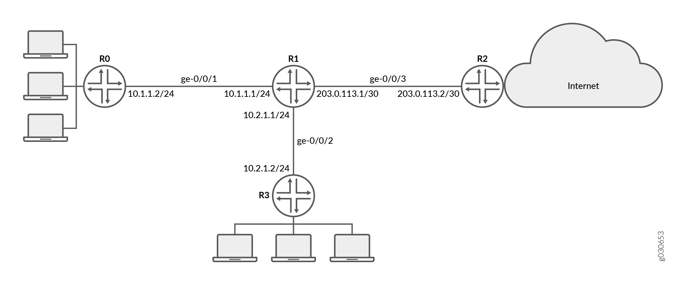
Your company’s branch offices are connected to each other through a private WAN. For this internal traffic, packet forwarding is required because security is not an issue. Hence for this traffic, you decide to configure selective stateless packet-based services to bypass flow-based forwarding. The remaining traffic, to and from the Internet, uses flow-based forwarding.
Configuration
Procedure
CLI Quick Configuration
To quickly configure this example, copy the
following commands, paste them into a text file, remove any line breaks,
change any details necessary to match your network configuration,
and then copy and paste the commands into the CLI at the [edit] hierarchy level, and then enter commit from configuration
mode.
{device R0}
[edit]
set interfaces ge-0/0/1 description "Internal 1" unit 0 family inet address 10.1.1.2/24
set routing-options static route 0.0.0.0/0 next-hop 10.1.1.1
{device R1}
set interfaces ge-0/0/1 description "Internal 1" unit 0 family inet address 10.1.1.1/24
set interfaces ge-0/0/2 description "Internal 2" unit 0 family inet address 10.2.1.1/24
set interfaces ge-0/0/3 description "Internet" unit 0 family inet address 203.0.113.1/30
set routing-options static route 0.0.0.0/0 next-hop 203.0.113.2
set security zones security-zone untrust interfaces ge-0/0/3
set security zones security-zone trust interfaces ge-0/0/1
set security zones security-zone trust interfaces ge-0/0/2
set security zones security-zone trust host-inbound-traffic system-services all
set security zones security-zone untrust host-inbound-traffic system-services all
set security policies from-zone trust to-zone untrust policy Internet-traffic match source-address any destination-address any application any
set security policies from-zone trust to-zone untrust policy Internet-traffic then permit
set security policies from-zone untrust to-zone trust policy Incoming-traffic match source-address any destination-address any application any
set security policies from-zone untrust to-zone trust policy Incoming-traffic then permit
set security policies from-zone trust to-zone trust policy Intrazone-traffic match source-address any destination-address any application any
set security policies from-zone trust to-zone trust policy Intrazone-traffic then permit
set firewall family inet filter bypass-flow-filter term bypass-flow-term-1 from source-address 10.1.1.0/24
set firewall family inet filter bypass-flow-filter term bypass-flow-term–1 from destination-address 10.2.1.0/24
set firewall family inet filter bypass-flow-filter term bypass-flow-term-1 then packet-mode
set firewall family inet filter bypass-flow-filter term bypass-flow-term-2 from source-address 10.2.1.0/24
set firewall family inet filter bypass-flow-filter term bypass-flow-term-2 from destination-address 10.1.1.0/24
set firewall family inet filter bypass-flow-filter term bypass-flow-term-2 then packet-mode
set firewall family inet filter bypass-flow-filter term accept-rest then accept
set interfaces ge-0/0/1 description "Internal 1" unit 0 family inet filter input bypass-flow-filer
set interfaces ge-0/0/2 description "Internal 2" unit 0 family inet filter input bypass-flow-filer
{device R2}
set interfaces ge-0/0/3 description "Internet" unit 0 family inet address 10.1.1.2/30
set routing-options static route 0.0.0.0/0 next-hop 10.1.1.1
{device R3}
[edit]
set interfaces ge-0/0/2 description "Internal 2" unit 0 family inet address 10.2.1.2/24
set routing-options static route 0.0.0.0/0 next-hop 10.2.1.1
Step-by-Step Procedure
The following example requires you to navigate various levels in the configuration hierarchy. For instructions on how to do that, see Using the CLI Editor in Configuration Mode in the CLI User Guide.
To configure selective stateless packet-based services for end-to-end packet-based forwarding:
-
Configure the IP addresses for the interfaces on devices R0, R1, R2, and R3.
{device R0} [edit] user@host#set interfaces ge-0/0/1 description "Internal 1" unit 0 family inet address 10.1.1.2/24{device R1} [edit] user@host#set interfaces ge-0/0/1 description "Internal 1" unit 0 family inet address 10.1.1.1/24user@host#set interfaces ge-0/0/2 description "Internal 2" unit 0 family inet address 10.2.1.1/24user@host#set interfaces ge-0/0/3 description "Internet" unit 0 family inet address 203.0.113.1/30{device R2} [edit] user@host#set interfaces ge-0/0/3 description "Internet" unit 0 family inet address 203.0.113.1/30{device R3} [edit] user@host#set interfaces ge-0/0/2 description "Internal 2" unit 0 family inet address 10.2.1.2/24 -
Create static routes and associate the appropriate next-hop addresses for devices R0, R1, R2, and R3.
{device R0} [edit] user@host#set routing-options static route 0.0.0.0/0 next-hop 10.1.1.1{device R1} [edit] user@host#set routing-options static route 0.0.0.0/0 next-hop 203.0.113.1{device R2} [edit] user@host#set routing-options static route 0.0.0.0/0 next-hop 203.0.113.2{device R3} [edit] user@host#set routing-options static route 0.0.0.0/0 next-hop 10.2.1.1 -
Configure security zones and assign interfaces.
{device R1} [edit] user@host#set security zones security-zone untrust interfaces ge-0/0/3user@host#set security zones security-zone trust interfaces ge-0/0/1user@host#set security zones security-zone trust interfaces ge-0/0/2 -
Configure application services for zones.
{device R1} [edit] user@host#set security zones security-zone trust host-inbound-traffic system-services alluser@host#set security zones security-zone untrust host-inbound-traffic system-services all -
Configure a security policy
{device R1} [edit] user@host#set security policies from-zone trust to-zone untrust policy Internet-traffic match source-address any destination-address any application anyuser@host#set security policies from-zone trust to-zone untrust policy Internet-traffic then permituser@host#set security policies from-zone untrust to-zone trust policy Incoming-traffic match source-address any destination-address any application anyuser@host#set security policies from-zone untrust to-zone trust policy Incoming-traffic then permituser@host#set security policies from-zone trust to-zone trust policy Intrazone-traffic match source-address any destination-address any application anyuser@host#set security policies from-zone trust to-zone trust policy Intrazone-traffic then permit -
Create a firewall filter and define terms for all the packet-based forwarding traffic.
{device R1} [edit] user@host#set firewall family inet filter bypass-flow-filter term bypass-flow-term-1 from source-address 10.1.1.0/24user@host#set firewall family inet filter bypass-flow-filter term bypass-flow-term–1 from destination-address 10.2.1.0/24user@host#set firewall family inet filter bypass-flow-filter term bypass-flow-term-1 then packet-modeuser@host#set firewall family inet filter bypass-flow-filter term bypass-flow-term-2 from source-address 10.2.1.0/24user@host#set firewall family inet filter bypass-flow-filter term bypass-flow-term-2 from destination-address 10.1.1.0/24user@host#set firewall family inet filter bypass-flow-filter term bypass-flow-term-2 then packet-mode -
Specify another term for the remaining traffic.
{device R1} [edit] user@host#set firewall family inet filter bypass-flow-filter term accept-rest then accept -
Apply the firewall filter to relevant interfaces.
{device R1} [edit] user@host#set interfaces ge-0/0/1 description "Internal 1" unit 0 family inet filter input bypass-flow-fileruser@host#set interfaces ge-0/0/2 description "Internal 2" unit 0 family inet filter input bypass-flow-filer
Results
From configuration mode, confirm your configuration
by entering the show interfaces, show routing-options, and show firewall commands. If the output does not display
the intended configuration, repeat the configuration instructions
in this example to correct it.
{device R0}
[edit]
user@host# show interfaces
ge-0/0/1 {
    description “Internal 1”
    unit 0 {
        family inet {
            address 10.1.1.2/24
        }
    }
}
{device R0}
[edit]
user@host# show routing-options
static {
    route 0.0.0.0/0 next-hop 10.1.1.1;
}
{device R2}
[edit]
user@host# show interfaces
ge-0/0/3 {
    description “Internet”
    unit 0 {
        family inet {
            address 203.0.113.2/30;
        }
    }
}
{device R2}
[edit]
user@host# show routing-options
static {
    route 0.0.0.0/0 next-hop 203.0.113.1;
}
{device R3}
[edit]
user@host# show interfaces
ge-0/0/2 {
    description “Internal 2”
    unit 0 {
        family inet {
            address 10.2.1.2/24;
        }
    }
}
{device R3}
user@host# show routing-options
static {
    route 0.0.0.0/0 next-hop 10.2.1.1;
}
{device R1}
[edit]
user@host# show interfaces
ge-0/0/1 {
    description “internal 1”
    unit 0 {
        family inet {
            filter {
                input bypass-flow-filter;
                }
            address 10.1.1.1/24;
        }
    }
}
ge-0/0/2 {
    description “Internal 2”
    unit 0 {
        family inet {
            filter {
                input bypass-flow-filter;
                }
            address 10.2.1.1/24;
        }
    }
}
ge-0/0/3 {
    description “Internet”
    unit 0 {
        family inet {
            address 203.0.113.1/30;
        }
    }
}
{device R1}
[edit]
user@host# show routing-options
static {
    route 0.0.0.0/0 next-hop 203.0.113.1;
}
{device R1}
[edit]
user@host# show firewall
family inet {
    filter bypass-flow-filter {
        term bypass-flow-term-1 {
            from {
                source-address {
                    10.1.1.0/24;
                }
                destination-address {
                    10.2.1.0/24;
                }
            }
            then packet-mode;
        }
        term bypass-flow-term-2 {
            from {
                source-address {
                    10.2.1.0/24;
                }
                destination-address {
                    10.1.1.0/24;
                }
            }
            then packet-mode;
        }
        term accept-rest {
            then accept;
        }
    }
}
If you are done configuring the device, enter commit from configuration mode.
Verification
Confirm that the configuration is working properly.
- Verifying the End-to-End Packet-Based Configuration
- Verifying Session Establishment on Intranet Traffic
- Verifying Session Establishment on Internet Traffic
Verifying the End-to-End Packet-Based Configuration
Purpose
Verify that the selective stateless packet-based services are configured.
Action
From configuration mode, enter the show interfaces, show routing-options, show security zones, show security policies, and show firewall commands.
Verify that the output shows the intended configuration of the firewall filter, interfaces, and policies.
Verify that the terms are listed in the order in which you want
the packets to be tested. You can move terms within a firewall filter
by using the insert command.
Verifying Session Establishment on Intranet Traffic
Purpose
Verify that sessions are established when traffic is transmitted to interfaces within the Intranet.
Action
To verify that sessions are established, perform the following tasks:
-
On device
R1, enter the operational modeclear security flow session allcommand to clear all existing security flow sessions. -
On device
R0, enter the operational modepingcommand to transmit traffic to deviceR3. -
On device
R1, with traffic transmitting from devicesR0toR3throughR1, enter the operational modeshow security flow sessioncommand.Flow Sessions on FPC10 PIC1: Total sessions: 0 Flow Sessions on FPC10 PIC2: Total sessions: 0 Flow Sessions on FPC10 PIC3: Total sessions: 0
To verify established sessions, make sure to enter the show security flow session command while the ping command is sending and receiving packets.
{device R0}
user@host> ping 203.0.113.6
PING 203.0.113.6 (203.0.113.6): 56 data bytes 64 bytes from 203.0.113.6: icmp_seq=0 ttl=63 time=2.326 ms 64 bytes from 203.0.113.6: icmp_seq=1 ttl=63 time=2.569 ms 64 bytes from 203.0.113.6: icmp_seq=2 ttl=63 time=2.565 ms 64 bytes from 203.0.113.6: icmp_seq=3 ttl=63 time=2.563 ms 64 bytes from 203.0.113.6: icmp_seq=4 ttl=63 time=2.306 ms 64 bytes from 203.0.113.6: icmp_seq=5 ttl=63 time=2.560 ms 64 bytes from 203.0.113.6: icmp_seq=6 ttl=63 time=4.130 ms 64 bytes from 203.0.113.6: icmp_seq=7 ttl=63 time=2.316 ms ...
{device R1}
user@host> show security flow session
Flow Sessions on FPC10 PIC1:
Total sessions: 0

Flow Sessions on FPC10 PIC2:
Total sessions: 0

Flow Sessions on FPC10 PIC3:
Total sessions: 0
The output shows traffic transmitting from R0 to R3 and no sessions are established. In this example, you applied
the bypass-flow-filter with the packet-mode action
modifier on interfaces Internal 1 and Internal 2 for your company’s Intranet traffic. This output verifies
that the traffic between the two interfaces is correctly bypassing
flow-based forwarding and hence no sessions are established.
Verifying Session Establishment on Internet Traffic
Purpose
Verify that sessions are established when traffic is transmitted to the Internet.
Action
To verify that traffic to the Internet is using flow-based forwarding and sessions are established, perform the following tasks:
-
On device
R1, enter the operational modeclear security flow session allcommand to clear all existing security flow sessions. -
On device
R0, enter the operational modepingcommand to transmit traffic to deviceR2. -
On device
R1, with traffic transmitting fromR0toR2throughR1, enter the operational modeshow security flow sessioncommand.
To verify established sessions, make sure to enter the show security flow session command while the ping command is sending and receiving packets.
{device R0}
user@host> ping 10.2.1.2 -c 10
PING 10.2.1.2 (10.2.1.2) 56(84) bytes of data. 64 bytes from 10.2.1.2: icmp_seq=1 ttl=63 time=6.07 ms 64 bytes from 10.2.1.2: icmp_seq=2 ttl=63 time=4.24 ms 64 bytes from 10.2.1.2: icmp_seq=3 ttl=63 time=2.85 ms 64 bytes from 10.2.1.2: icmp_seq=4 ttl=63 time=6.14 ms ...
{device R1}
user@host>show security flow session
Flow Sessions on FPC10 PIC1: Session ID: 410000077, Policy name: Internet-traffic/5, Timeout: 2, Valid In: 10.1.1.2/3 --> 10.2.1.2/32055;icmp, If: ge-0/0/1.0, Pkts: 1, Bytes: 84, CP Session ID: 410000198 Out: 10.2.1.2/32055 --> 10.1.1.2/3;icmp, If: ge-0/0/2.0, Pkts: 1, Bytes: 84, CP Session ID: 410000198 Total sessions: 1 Flow Sessions on FPC10 PIC2: Session ID: 420000079, Policy name: Internet-traffic/5, Timeout: 2, Valid In: 10.1.1.2/5 --> 10.2.1.2/32055;icmp, If: ge-0/0/1.0, Pkts: 1, Bytes: 84, CP Session ID: 420000163 Out: 10.2.1.2/32055 --> 10.1.1.2/5;icmp, If: ge-0/0/2.0, Pkts: 1, Bytes: 84, CP Session ID: 420000163 Total sessions: 1 Flow Sessions on FPC10 PIC3: Session ID: 430000090, Policy name: Internet-traffic/5, Timeout: 4, Valid In:10.1.1.2/7 --> 10.2.1.2/32055;icmp, If: ge-0/0/1.0, Pkts: 1, Bytes: 84, CP Session ID: 430000088 Out: 10.2.1.2/32055 --> 10.1.1.2/7;icmp, If: ge-0/0/2.0, Pkts: 1, Bytes: 84, CP Session ID: 430000088 Total sessions: 1
The output shows traffic transmitting from devices R0 to R1 and established sessions. In this example, you
did not apply the bypass-flow-filter with the packet-mode action modifier on interface Internet for your company’s
Internet traffic. This output verifies that the traffic to the Internet
is correctly using flow-based forwarding and hence sessions are established.
Transmit traffic from device R3 to R2 and
use the commands in this section to verify established sessions.
Example: Configuring Selective Stateless Packet-Based Services for Packet-Based to Flow-Based Forwarding
This example shows how to configure selective stateless packet-based services for packet-based to flow-based forwarding. This feature is supported on SRX300, SRX320, SRX340, SRX345, and vSRX Virtual Firewall devices.
Requirements
Before you begin:
-
Understand how to configure stateless firewall filters.
-
Establish basic connectivity. .
Overview
In this example, you configure the IP addresses for the interfaces on each of the devices. For device R0 as 198.51.100.9/24; for R1 the are198.51.100.10/24 and 203.0.113.5/24; and for R2 it is 203.0.113.9/24. On device R1, you set an internal service interface lt-0/0/0 between routing instances and configure a peer relationship between two virtual devices. You then create two security zones, Primary-VR-zone and Internet-VR-zone, assign related interfaces to them, and configure them to allow all supported applications and protocols.
Then you configure policies and specify that all packets are permitted. You configure a virtual device routing instance Internet-VR and assign interfaces for flow-based forwarding. You enable OSPF on devices R0, R1, and R2. On Device R2, you configure the filter bypass-flow-filter with the term bypass-flow-term that contains the packet-mode action modifier. Because you have not specified any match conditions, this filter applies to all traffic that traverses the interfaces on which it is applied.
Finally, on device R1 you apply the firewall filter bypass-flow-filter to internal interfaces ge-0/0/2.0 and lt-0/0/0.0. You do not apply the filter to the interfaces associated with the Internet-VR routing instance. As a result, all traffic that traverses the LAN interfaces associated with the primary routing instance uses packet-based forwarding and all traffic that traverses the Internet-VR routing instance uses flow-based forwarding.
Figure 4 shows the network topology used in this example.
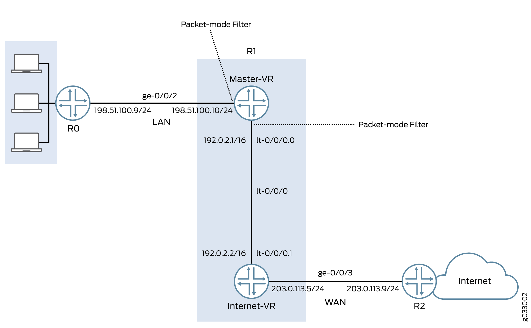
The interface facing the private LAN does not need any security services, but the interface facing the WAN needs security. In this example, you decide to configure both packet-based and flow-based forwarding for secure and not so secure traffic by configuring two routing instances—one handling the packet-based forwarding and the other handling the flow-based forwarding.
Configuration
Procedure
CLI Quick Configuration
To quickly configure this example, copy the
following commands, paste them into a text file, remove any line breaks,
change any details necessary to match your network configuration,
and then copy and paste the commands into the CLI at the [edit] hierarchy level, and then enter commit from configuration
mode.
{device R0}
set interfaces description “Connect to Primary VR” ge-0/0/2 unit 0 family inet address 198.51.100.9/24
set protocols ospf area 0.0.0.0 interface ge-0/0/2.0
{device R1}
set interfaces description “Connect to R0” ge-0/0/2 unit 0 family inet address 198.51.100.10/24
set interfaces description “Connect to R2” ge-0/0/3 unit 0 family inet address 203.0.113.5/24
set interfaces lt-0/0/0 unit 0 encapsulation frame-relay dlci 100 peer-unit 1 family inet address 192.0.2.1/16
set interfaces lt-0/0/0 unit 1 encapsulation frame-relay dlci 100 peer-unit 0 family inet address 192.0.2.2/16
set security zones security-zone Primary-VR-zone host-inbound-traffic system-services all
set security zones security-zone Primary-VR-zone host-inbound-traffic protocols all
set security zones security-zone Primary-VR-zone interfaces ge-0/0/2.0
set security zones security-zone Primary-VR-zone interfaces lt-0/0/0.0
set security zones security-zone Internet-VR-zone host-inbound-traffic system-services all
set security zones security-zone Internet-VR-zone host-inbound-traffic protocols all
set security zones security-zone Internet-VR-zone interfaces ge-0/0/3.0
set security zones security-zone Internet-VR-zone interfaces lt-0/0/0.1
set security policies default-policy permit-all
set routing-instances Internet-VR instance-type virtual-router interface lt-0/0/0.1
set routing-instances Internet-VR instance-type virtual-router interface ge-0/0/3.0
set protocols ospf area 0.0.0.0 interface ge-0/0/2.0
set protocols ospf area 0.0.0.0 interface lt-0/0/0.0
set routing-instances Internet-VR protocols ospf area 0.0.0.0 interface lt-0/0/0.1
set routing-instances Internet-VR protocols ospf area 0.0.0.0 interface ge-0/0/3.0
set firewall family inet filter bypass-flow-filter term bypass-flow-term then accept
set firewall family inet filter bypass-flow-filter term bypass-flow-term then packet-mode
set interfaces ge-0/0/2 unit 0 family inet filter input bypass-flow-filter
set interfaces lt-0/0/0 unit 0 family inet filter input bypass-flow-filter
{device R2}
set interfaces description “Connect to Internet-VR” ge-0/0/3 unit 0 family inet address 203.0.113.9/24
set protocols ospf area 0.0.0.0 interface ge-0/0/3
Step-by-Step Procedure
The following example requires you to navigate various levels in the configuration hierarchy. For instructions on how to do that, see Using the CLI Editor in Configuration Mode in the CLI User Guide.
To configure selective stateless packet-based services for end-to-end packet-based forwarding:
-
Configure the IP addresses for the interfaces.
{device R0} [edit] user@host#set interfaces description “Connect to Primary VR” ge-0/0/2 unit 0 family inet address 198.51.100.9/24{device R1} [edit] user@host#set interfaces description “Connect to R0” ge-0/0/2 unit 0 family inet address 198.51.100.10/24user@host#set interfaces description “Connect to R2” ge-0/0/3 unit 0 family inet address 203.0.113.5/24{device R2} [edit] user@host#set interfaces description “Connect to Internet-VR” ge-0/0/3 unit 0 family inet address 203.0.113.9/24 -
Set an internal service interface between routing instances.
{device R1} [edit] user@host#set interfaces lt-0/0/0 unit 0 encapsulation frame-relay dlci 100 peer-unit 1 family inet address 192.0.2.1/16user@host#set interfaces lt-0/0/0 unit 1 encapsulation frame-relay dlci 100 peer-unit 0 family inet address 192.0.2.2/16 -
Configure security zones.
{device R1} [edit] user@host#set security zones security-zone Primary-VR-zone host-inbound-traffic system-services alluser@host#set security zones security-zone Primary-VR-zone host-inbound-traffic protocols alluser@host#set security zones security-zone Primary-VR-zone interfaces ge-0/0/2.0user@host#set security zones security-zone Primary-VR-zone interfaces lt-0/0/0.0user@host#set security zones security-zone Internet-VR-zone host-inbound-traffic system-services alluser@host#set security zones security-zone Internet-VR-zone host-inbound-traffic protocols alluser@host#set security zones security-zone Internet-VR-zone interfaces ge-0/0/3.0user@host#set security zones security-zone Internet-VR-zone interfaces lt-0/0/0.1 -
Configure policies.
{device R1} [edit] user@host#set security policies default-policy permit-all -
Configure a virtual device routing instance.
{device R1} [edit] user@host#set routing-instances Internet-VR instance-type virtual-router interface lt-0/0/0.1user@host#set routing-instances Internet-VR instance-type virtual-router interface ge-0/0/3.0 -
Enable OSPF on all interfaces in the network.
{device R0} [edit] user@host#set protocols ospf area 0.0.0.0 interface ge-0/0/2.0{device R1 for Primary-VR} [edit] user@host#set protocols ospf area 0.0.0.0 interface ge-0/0/2.0user@host#set protocols ospf area 0.0.0.0 interface lt-0/0/0.0{device R1 for Internet-VR} [edit] user@host#set routing-instances Internet-VR protocols ospf area 0.0.0.0 interface lt-0/0/0.1user@host#set routing-instances Internet-VR protocols ospf area 0.0.0.0 interface ge-0/0/3.0{device R2} [edit] user@host#set protocols ospf area 0.0.0.0 interface ge-0/0/3 -
Create a firewall filter and define a term for packet-based forwarding traffic.
{device R1} [edit] user@host#set firewall family inet filter bypass-flow-filter term bypass-flow-term then acceptuser@host#set firewall family inet filter bypass-flow-filter term bypass-flow-term then packet-mode -
Apply the firewall filter to relevant interfaces.
{device R1} [edit] user@host#set interfaces ge-0/0/2 unit 0 family inet filter input bypass-flow-filteruser@host#set interfaces lt-0/0/0 unit 0 family inet filter input bypass-flow-filter
Results
From configuration mode, confirm your configuration
by entering the show interfaces, show protocols, show security, show routing-instances, and show firewall commands. If the output does not display the
intended configuration, repeat the configuration instructions in this
example to correct it.
{device R0}
[edit]
user@host# show interfaces
ge-0/0/2 {
description “Connect to Primary-VR”
unit 0 {
family inet {
address 198.51.100.9/24
}
}
}
{device R0}
[edit]
user@host# show protocols
ospf {
area 0.0.0.0/0 {
interface ge-0/0/2.0;
}
}
{device R2}
[edit]
user@host# show interfaces
ge-0/0/3 {
description “Connect to Internet-VR”
unit 0 {
family inet {
address 203.0.113.9/24;
}
}
}
{device R2}
[edit]
user@host# show protocols
ospf {
area 0.0.0.0/0 {
interface ge-0/0/3.0;
}
}
{device R1}
[edit]
user@host# show interfaces
ge-0/0/2 {
description “Connect to R0”
unit 0 {
family inet {
filter {
input bypass-flow-filter;
}
address 198.51.100.10/24;
}
}
}
lt-0/0/0 {
unit 0 {
encapsulation frame-relay;
dlci 100;
peer-unit 1;
family inet {
filter {
input bypass-flow-filter
}
address 192.0.2.1/16;
}
}
unit 1{
encapsulation frame-relay;
dlci 100;
peer-unit 0;
family inet {
address 192.0.2.2/16 ;
}
}
}
{device R1}
[edit]
user@host# show protocols
ospf {
area 0.0.0.0/0 {
interface ge-0/0/2.0;
interface lt-0/0/0.0;
}
}
{device R1}
[edit]
user@host# show firewall
filter bypass-flow-filter {
term bypass-flow-term {
then {
packet-mode;
accept;
}
}
}
{device R1}
[edit]
user@host# show routing-instances
Internet-VR {
instance-type virtual-router;
interface lt-0/0/0.1;
interface ge-0/0/3.0;
protocols {
ospf {
area 0.0.0.0 {
interface ge-0/0/3.0;
lt-0/0/0.1;
}
}
}
}
{device R1}
[edit]
user@host# show security
security zone Primary-VR-zone {
host-inbound-traffic {
system-services {
all;
{
protocols {
all;
{
{
intefaces {
ge-0/0/2.0;
lt-0/0/0.0;
{
{
security zone Internet-VR-zone {
host-inbound-traffic {
system-services {
all;
{
protocols {
all;
}
}
intefaces {
ge-0/0/3.0;
lt-0/0/0.1;
{
{
policies {
default-policy {
permit-all;
}
}
If you are done configuring the device, enter commit from configuration mode.
Verification
Confirm that the configuration is working properly.
- Verifying the Packet-Based to Flow-Based Configuration
- Verifying Session Establishment on LAN Traffic
- Verifying Session Establishment on Internet Traffic
Verifying the Packet-Based to Flow-Based Configuration
Purpose
Verify that the selective stateless packet-based services are configured for packet-based to flow-based forwarding.
Action
From configuration mode, enter the show interfaces, show protocols, show security, show
routing-instances, and show firewall commands.
Verify that the output shows the intended configuration of the firewall filter, routing instances, interfaces, and policies.
Verify that the terms are listed in the order in which you want
the packets to be tested. You can move terms within a firewall filter
by using the insert command.
Verifying Session Establishment on LAN Traffic
Purpose
Verify that the sessions are established when traffic is transmitted on interfaces within the LAN.
Action
To verify that sessions are established, perform the following tasks:
-
On device
R1, from operational mode enter theclear security flow session allcommand to clear all existing security flow sessions. -
On device
R0, from operational mode enter thepingcommand to transmit traffic to devicePrimary-VR. -
On device
R1, with traffic transmitting from devicesR0throughR1, from operational mode enter theshow security flow sessioncommand.
To verify established sessions, ensure that you enter
the show security flow session command while the ping command is sending and receiving packets.
{device R0}
user@host> ping 192.0.2.1
PING 192.0.2.1 (192.0.2.1): 56 data bytes 64 bytes from 192.0.2.1: icmp_seq=0 ttl=63 time=2.208 ms 64 bytes from 192.0.2.1: icmp_seq=1 ttl=63 time=2.568 ms 64 bytes from 192.0.2.1: icmp_seq=2 ttl=63 time=2.573 ms 64 bytes from 192.0.2.1: icmp_seq=3 ttl=63 time=2.310 ms 64 bytes from 192.0.2.1: icmp_seq=4 ttl=63 time=1.566 ms 64 bytes from 192.0.2.1: icmp_seq=5 ttl=63 time=1.569 ms ...
{device R1}
user@host> show security flow session
0 sessions displayed
The output shows traffic transmitting from R0 to Primary-VR and no sessions are established. In this example,
you applied the bypass-flow-filter with the packet-mode action modifier on interfaces ge-0/0/0 and lt-0/0/0.0 for your company’s LAN traffic. This output verifies that
the traffic between the two interfaces is correctly bypassing flow-based
forwarding and hence no sessions are established.
Verifying Session Establishment on Internet Traffic
Purpose
Verify that sessions are established when traffic is transmitted to the Internet.
Action
To verify that traffic to the Internet is using flow-based forwarding and sessions are established, perform the following tasks:
-
On device
R1, from operational mode enter theclear security flow session allcommand to clear all existing security flow sessions. -
On device
R0, from operational mode enter thepingcommand to transmit traffic to deviceR2. -
On device
R1, with traffic transmitting fromR0toR2throughR1, from operational mode enter theshow security flow sessioncommand.root@host> show security flow session Flow Sessions on FPC10 PIC1: Total sessions: 0 Flow Sessions on FPC10 PIC2: Total sessions: 0 Flow Sessions on FPC10 PIC3: Total sessions: 0
To verify established sessions, ensure that you enter
the show security flow session command while the ping command is sending and receiving packets.
{device R0}
user@host> ping 192.0.2.1 -c 10
PING 60.0.0.1 (60.0.0.1) 56(84) bytes of data. 64 bytes from 192.0.2.1: icmp_seq=1 ttl=64 time=1.98 ms 64 bytes from 192.0.2.1: icmp_seq=2 ttl=64 time=1.94 ms 64 bytes from 192.0.2.1: icmp_seq=3 ttl=64 time=1.92 ms 64 bytes from 192.0.2.1: icmp_seq=4 ttl=64 time=1.89 ms ...
{device R1}
user@host> show security flow session
Session ID: 189900, Policy name: default-policy/2, Timeout: 2
  In: 198.51.100.9/0 --> 192.0.2.1/5924;icmp, If: lt-0/0/0.1
  Out: 192.0.2.1/5924 --> 198.51.100.9/0;icmp, If: ge-0/0/3.0

Session ID: 189901, Policy name: default-policy/2, Timeout: 2
  In: 198.51.100.9/1 --> 192.0.2.1/5924;icmp, If: lt-0/0/0.1
  Out: 192.0.2.1/5924 --> 198.51.100.9/1;icmp, If: ge-0/0/3.0

Session ID: 189902, Policy name: default-policy/2, Timeout: 4
  In: 198.51.100.9/2 --> 192.0.2.1/5924;icmp, If: lt-0/0/0.1
  Out: 192.0.2.1/5924 --> 198.51.100.9/2;icmp, If: ge-0/0/3.0

 3 sessions displayed
The output shows traffic transmitting from devices R0 to R2 and established sessions. In this example, you
did not apply the bypass-flow-filter with the packet-mode action modifier on routing instance Internet-VR for your
company’s Internet traffic. This output verifies that the traffic
to the Internet is correctly using flow-based forwarding and hence
sessions are established.
Note that sessions are established only when traffic is flowing
between lt-0/0/0.1 and ge-0/0/3 and not when
traffic is flowing between ge-0/0/2 and lt-0/0/0.0.
Change History Table
Feature support is determined by the platform and release you are using. Use Feature Explorer to determine if a feature is supported on your platform.