ON THIS PAGE
Understanding Central Point Architecture Enhancements for NAT
Example: Configuring Source NAT for Egress Interface Translation
Example: Configuring Source NAT for Single Address Translation
Example: Configuring Source and Destination NAT Translations
Example: Configuring Source NAT for Multiple Addresses with PAT
Example: Configuring a Single IP Address in a Source NAT Pool Without PAT
Example: Configuring Multiple Addresses in a Source NAT Pool Without PAT
Understanding Shared Addresses in Source NAT Pools without PAT
Configuring the NAT Session Hold Timeout and NAT Session Persistence Scan
Understanding NAT Configuration Check on Egress Interfaces after Reroute
Source NAT
Source NAT is most commonly used for translating private IP address to a public routable address to communicate with the host. Source NAT changes the source address of the packets that pass through the Router. A NAT pool is a set of addresses that are designed as a replacement for client IP addresses. For more information, see the following topics:
Understanding Source NAT
Source NAT is the translation of the source IP address of a packet leaving the Juniper Networks device. Source NAT is used to allow hosts with private IP addresses to access a public network.
Source NAT allows connections to be initiated only for outgoing network connections—for example, from a private network to the Internet. Source NAT is commonly used to perform the following translations:
-
Translate a single IP address to another address (for example, to provide a single device in a private network with access to the Internet).
-
Translate a contiguous block of addresses to another block of addresses of the same size.
-
Translate a contiguous block of addresses to another block of addresses of smaller size.
-
Translate a contiguous block of addresses to a single IP address or a smaller block of addresses using port translation.
-
Translate a contiguous block of addresses to the address of the egress interface.
Translation to the address of the egress interface does not require an address pool; all other source NAT translations require configuration of an address pool. One-to-one and many-to-many translations for address blocks of the same size do not require port translation because there is an available address in the pool for every address that would be translated.
If the size of the address pool is smaller than the number of addresses that would be translated, either the total number of concurrent addresses that can be translated is limited by the size of the address pool or port translation must be used. For example, if a block of 253 addresses is translated to an address pool of 10 addresses, a maximum of 10 devices can be connected concurrently unless port translation is used.
The following types of source NAT are supported:
-
Translation of the original source IP address to the egress interface’s IP address (also called interface NAT). Port address translation is always performed.
-
Translation of the original source IP address to an IP address from a user-defined address pool without port address translation. The association between the original source IP address to the translated source IP address is dynamic. However, once there is an association, the same association is used for the same original source IP address for new traffic that matches the same NAT rule.
-
Translation of the original source IP address to an IP address from a user-defined address pool with port address translation. The association between the original source IP address to the translated source IP address is dynamic. Even if an association exists, the same original source IP address may be translated to a different address for new traffic that matches the same NAT rule.
-
Translation of the original source IP address to an IP address from a user-defined address pool by shifting the IP addresses. This type of translation is one-to-one, static, and without port address translation. If the original source IP address range is larger than the IP address range in the user-defined pool, untranslated packets are dropped.
On the MX Series device, if you use the Source NAT on an aggregated multiservices (AMS)
interface. The service set command creates a separate entry for each
AMS interface. Hence, the memory utilization exhausts and if you configure an additional
AMS interface results in configuration commit error.
Subscriber Port Utilization Alarm
You can use Carrier Grade Network Address Translation (CGNAT) to monitor and manage
port utilization. Use the set secuirty nat source
subscriber-pool-utilization-alarm to configure threshold limits to
receive notifications when port or port block usage exceeds the configured
thresholds.
If a pool is configured as Port Block Allocation (PBA) and a subscriber uses more port blocks than the threshold, a notification is generated.
For Deterministic NAT (DETNAT) pools, if a subscriber uses more ports than the threshold in the allocated block, a notification is generated.
Dampening Interval
When the configured threshold limit is crossed, the system sends a RAISE_ALARM, followed by a suppression period, during which no further alarms are sent.
Use the configurable timer to prevent system log or SNMP servers from being flooded
with frequent alarm notifications using the dampening-interval at
[set secuirty nat source subscriber-pool-utilization-alarm]
hierarchy.
If the CLEAR_ALARM is not triggered, the suppression period continuous. If the CLEAR_ALARM is received within the suppression period, the system logs will be removed from timer and CLEAR_ALARM is sent.
For more information, see subscriber-pool-utilization-alarm and show security nat source port-block.
Understanding Central Point Architecture Enhancements for NAT
System session capacity and session ramp-up rate are limited by central point memory capacity and CPU capacity. The following list describes the enhancements to NAT to improve performance:
The central point architecture no longer supports central point sessions. Therefore, NAT needs to maintain a NAT tracker to track the IP address or port allocation and usage. NAT tracker is a global array for SPU session ID to NAT IP or port mapping that is used to manage NAT resources.
By default, a NAT rule alarm and trap statistics counter update message is sent from the Services Processing Unit (SPU) to the central point at intervals of 1 second instead of updating the statistics based on each session trigger in the central point system.
To support a specific NAT IP address or port allocated such that the 5-tuple hash after NAT is the same as the original 5-tuple hash before NAT, select a NAT port that results in the same hash as the original hash by the specific calculation. Hence, the forwarding session is reduced. When NAT is used, the reverse wing is hashed to a different SPU. A forward session has to be installed to forward reverse traffic to a session SPU. NAT tries to select a port that can be used by the hash algorithm to make the reverse wing be hashed to the same SPU as the initial wing. So, both NAT performance and throughput are improved with this approach.
To improve NAT performance, IP shifting pool (non-PAT pool) management is moved from the central point to the SPU so that all local NAT resources for that pool are managed locally instead of sending the NAT request to the central point. Hence, IP address-shifting NAT pool connections per second and throughput are improved.
Port Overflow Burst Mode
The port overflow burst mode allows you to use the ports beyond the allocated port blocks. You can configure a burst pool with a range of ports in an IP address to be reserved for bursting.
There are primary and burst pool types, the device uses the burst pool once the subscribers reach the limit configured in the primary pool.
Brust mode is supported on:
Deterministic NAT source NAT pool with PBA type burst pool.
Deterministic NAT source NAT pool with dynamic Network Address Port Translation (NAPT) type burst pool.
Regular PBA source NAT pool with PBA type burst pool.
Regular PBA source NAT pool with dynamic NAPT type burst pool.
|
NAT Type |
Before the Configured Port Block Limit not Exceed |
After the Configured Port Block Limit not Exceed |
|---|---|---|
|
Deterministic NAT source NAT pool with PBA type burst pool |
Port blocks from the primary DetNAT pool are used. |
Port block from the burst pool configured in PBA. |
|
Deterministic NAT source NAT pool with dynamic Network Address Port Translation (NAPT) type burst pool |
Port blocks from the primary DetNAT pool are used. |
Port block from the burst pool configured in dynamic NAPT. |
|
Regular PBA source NAT pool with PBA type burst pool |
Port blocks from the primary PBA pool are used. |
Port block from the burst pool configured in PBA. |
|
Regular PBA source NAT pool with dynamic NAPT type burst pool |
Port blocks from the primary PBA pool are used. |
Port block from the burst pool configured in dynamic NAPT. |
PBA Burst Type Method—PBA supports APP and non-APP mode of operations.
-
APP Mode—Ports are allocated from the primary pool. When then subscriber limit exceeds from primary pool, if there are any available ports for the same IP address from the burst pool, then new sessions are created.
-
non-APP Mode—Ports are allocated from the primary pool. When subscriber limit exceeds from primary pool, new sessions are created from the burst pool with any available IP address and port.
DetNAT Burst Type Method—Ports are allocated from the primary pool. If the same IP address from the burst pool or all the available ports are not available from same IP address, then new session are created with another IP address. If the burst pool is configured with a different IP from primary pool, uses another IP from the burst pool.
Optimizing Source NAT Performance
Source NAT can be optimized based on functionality and performance needs.
Port Randomization Mode (Default)
For pool-based source NAT and interface NAT, port randomization mode is enabled and used by default.
In this mode, the device selects IP addresses on a round-robin basis, and the port selection is random. That is, when the device performs NAT translation it first chooses the IP address by round robin, then chooses the port used for that IP address by randomization.
Although randomized port number allocation can provide protection from security threats such as DNS poison attacks, it can also affect performance and memory usage due to the computations and NAT table resources involved.
Round-Robin Mode
A less resource-intensive NAT translation method involves using only the round-robin allocation method. Whereas randomization requires computational work for each assigned port, the round robin method simply selects ports sequentially.
In this mode, the device selects both IP addresses and ports on a round-robin basis. That is, when the device performs NAT translation it first chooses the IP address by round robin, then chooses the port used for that IP address by round robin.
For example, if the source pool contains only one IP address:
When the first packet of a flow arrives (creating a session), it is translated to IP1, port N. Subsequent packets in that flow are allocated to the same IP/port.
When the first packet of a new flow arrives, it is translated to IP1, port N+1, and so on.
If the source pool contains two IP addresses:
When the first packet of a flow arrives (creating a session), it is translated to IP1, port X. Subsequent packets in that flow are allocated to the same IP/port.
When the first packet of a second flow arrives, it is translated to IP2, port X.
When the first packet of a third flow arrives, it is translated to IP1, port X+1.
With the first packets of a fourth flow arrives, it is translated to IP2, port X+1, and so on.
Configuration
Round-robin mode is enabled by default, however port randomization mode (also enabled) has higher priority. To use round-robin mode, disable the higher-priority port randomization mode, as follows:
user@host# set security nat source port-randomization disable
To disable round-robin mode (and re-enable port randomization), delete the configuration statement, as follows:
user@host# delete security nat source port-randomization disable
Session Affinity Mode
With the modes noted above, a given session is processed by the inbound SPU based on a 5-tuple (source IP, dest IP, source port, dest port, protocol) hash. When NAT is involved, the 5-tuple hash will be different for the outbound part of the session vs. the return part of the session. Therefore, the outbound NAT session information may be located in one SPU, while the return (reverse) NAT session information may be located in another SPU. The goal of session affinity mode is to maintain the forwarding session information for both the outbound and return traffic on the same SPU.
In this mode, the device uses a “reverse NAT enhancement” translation algorithm for IP and port selection, to improve performance for NAT sessions and throughput. The NAT module attempts to select an IP address and port that can be used with the hash algorithm to ensure the selected SPU for the outbound and return flow elements can be identical.
Configuration
Session affinity mode is enabled by default, however both port randomization and round-robin modes (also enabled) have higher priority. To use session affinity mode, disable both port randomization and round-robin modes, as follows:
user@host# set security nat source port-randomization disable
user@host# set security nat source port-round-robin disable
To disable session affinity mode, and re-enable either round-robin or port randomization mode, delete one or both of the configuration statements, as follows:
user@host# delete security nat source port-round-robin disable
user@host# delete security nat source port-randomization disable
Usage Notes
Notes and guidelines for session affinity mode include:
Use large NAT port pools whenever possible (see Security Considerations below)
The algorithm chooses a port from within the configured port range. If no port is available, the NAT port will be allocated based on random selection.
Static NAT and destination NAT cannot use affinity mode.
Security Considerations
Although session affinity improves performance by consolidating forwarding sessions, it decreases security to some degree since the algorithm selects the IP address and port based on a pre-defined algorithm with specific parameters, instead of pure randomization. That said, the fact there are typically multiple eligible ports for the algorithm to choose from and so there is still some degree of randomization.
The best way to mitigate the security risk is to ensure the source port number used is less predictable. That is, the larger the NAT pool resource range from which ephemeral ports are selected, the smaller the chances of an attacker guessing the selected port number. Given this, it is recommended to configure large NAT port pools whenever possible.
Monitoring Source NAT Information
Purpose
Display configured information about source Network Address Translation (NAT) rules, pools, persistent NAT, and paired addresses.
Action
Select Monitor>NAT>Source NAT in the J-Web user interface, or enter the following CLI commands:
show security nat source summary
show security nat source pool pool-name
show security nat source persistent-nat-table
show security nat source paired-address
Table 2 describes the available options for monitoring source NAT.
Field |
Description |
Action |
|---|---|---|
| Rules | ||
Rule-set Name |
Name of the rule set. |
Select all rule sets or a specific rule set to display from the list. |
Total rules |
Number of rules configured. |
– |
ID |
Rule ID number. |
– |
Name |
Name of the rule . |
– |
From |
Name of the routing instance/zone/interface from which the packet flows. |
– |
To |
Name of the routing instance/zone/interface to which the packet flows. |
– |
Source address range |
Source IP address range in the source pool. |
– |
Destination address range |
Destination IP address range in the source pool. |
– |
Source ports |
Source port numbers. |
– |
Ip protocol |
IP protocol. |
– |
Action |
Action taken for a packet that matches a rule. |
– |
Persistent NAT type |
Persistent NAT type. |
– |
Inactivity timeout |
Inactivity timeout interval for the persistent NAT binding. |
– |
Alarm threshold |
Utilization alarm threshold. |
|
Max session number |
The maximum number of sessions. |
– |
Sessions (Succ/Failed/Current) |
Successful, failed, and current sessions.
|
– |
Translation Hits |
Number of times a translation in the translation table is used for a source NAT rule. |
– |
| Pools | ||
Pool Name |
The names of the pools. |
Select all pools or a specific pool to display from the list. |
Total Pools |
Total pools added. |
– |
ID |
ID of the pool. |
– |
Name |
Name of the source pool. |
– |
Address range |
IP address range in the source pool. |
– |
Single/Twin ports |
Number of allocated single and twin ports. |
– |
Port |
Source port number in the pool. |
– |
Address assignment |
Displays the type of address assignment. |
– |
Alarm threshold |
Utilization alarm threshold. |
– |
Port overloading factor |
Port overloading capacity. |
– |
Routing instance |
Name of the routing instance. |
– |
Total addresses |
Total IP address, IP address set, or address book entry. |
– |
Host address base |
Host base address of the original source IP address range. |
– |
Translation hits |
Number of times a translation in the translation table is used for source NAT. |
– |
| Top 10 Translation Hits | ||
Graph |
Displays the graph of top 10 translation hits. |
– |
| Persistent NAT | ||
| Persistent NAT table statistics | ||
binding total |
Displays the total number of persistent NAT bindings for the FPC. |
– |
binding in use |
Number of persistent NAT bindings that are in use for the FPC. |
– |
enode total |
Total number of persistent NAT enodes for the FPC. |
– |
enode in use |
Number of persistent NAT enodes that are in use for the FPC. |
– |
| Persistent NAT table | ||
Source NAT pool |
Name of the pool. |
Select all pools or a specific pool to display from the list. |
Internal IP |
Internal IP address. |
Select all IP addresses or a specific IP address to display from the list. |
Internal port |
Displays the internal ports configured in the system. |
Select the port to display from the list. |
Internal protocol |
Internal protocols . |
Select all protocols or a specific protocol to display from the list. |
Internal IP |
Internal transport IP address of the outgoing session from internal to external. |
– |
Internal port |
Internal transport port number of the outgoing session from internal to external. |
– |
Internal protocol |
Internal protocol of the outgoing session from internal to external. |
– |
Reflective IP |
Translated IP address of the source IP address. |
– |
Reflective port |
Displays the translated number of the port. |
– |
Reflective protocol |
Translated protocol. |
– |
Source NAT pool |
Name of the source NAT pool where persistent NAT is used. |
– |
Type |
Persistent NAT type. |
– |
Left time/Conf time |
Inactivity timeout period that remains and the configured timeout value. |
– |
Current session num/Max session num |
Number of current sessions associated with the persistent NAT binding and the maximum number of sessions. |
– |
Source NAT rule |
Name of the source NAT rule to which this persistent NAT binding applies. |
– |
| External node table | ||
Internal IP |
Internal transport IP address of the outgoing session from internal to external. |
– |
Internal port |
Internal port number of the outgoing session from internal to external. |
– |
External IP |
External IP address of the outgoing session from internal to external. |
– |
External port |
External port of the outgoing session from internal to external. |
– |
Zone |
External zone of the outgoing session from internal to external. |
– |
| Paired Address | ||
Pool name |
Name of the pool. |
Select all pools or a specific pool to display from the list. |
Specified Address |
IP address. |
Select all addresses, or select the internal or external IP address to display, and enter the IP address. |
Pool name |
Displays the selected pool or pools. |
– |
Internal address |
Displays the internal IP address. |
– |
External address |
Displays the external IP address. |
– |
| Resource Usage | ||
| Utilization for all source pools | ||
Pool name |
Name of the pool. |
To view additional usage information for Port Address Translation (PAT) pools, select a pool name. The information displays under Detail Port Utilization for Specified Pool. |
Pool type |
Pool type: PAT or Non-PAT. |
– |
Port overloading factor |
Port overloading capacity for PAT pools. |
– |
Address |
Addresses in the pool. |
– |
Used |
Number of used resources in the pool. For Non-PAT pools, the number of used IP addresses is displayed. For PAT pools, the number of used ports is displayed. |
– |
Available |
Number of available resources in the pool. For Non-PAT pools, the number of available IP addresses is displayed. For PAT pools, the number of available ports is displayed. |
– |
Total |
Number of used and available resources in the pool. For Non-PAT pools, the total number of used and available IP addresses is displayed. For PAT pools, the total number of used and available ports is displayed. |
– |
Usage |
Percent of resources used. For Non-PAT pools, the percent of IP addresses used is displayed. For PAT pools, the percent of ports, including single and twin ports, is displayed. |
– |
Peak usage |
Percent of resources used during the peak date and time. |
– |
| Detail Port Utilization for Specified Pool | ||
Address Name |
IP addresses in the PAT pool. |
Select the IP address for which you want to display detailed usage information. |
Factor-Index |
Index number. |
– |
Port-range |
Displays the number of ports allocated at a time. |
– |
Used |
Displays the number of used ports. |
– |
Available |
Displays the number of available ports. |
– |
Total |
Displays the number of used and available ports. |
– |
Usage |
Displays the percentage of ports used during the peak date and time. |
– |
Monitor Subscriber Port Utilization Using Carrier Grade NAT
Before you begin:
-
Understand the guidelines for monitoring subscriber port utilization. Read Configure Port Block Allocation Size.
You can configure threshold limits to monitor port utilization, by receiving notifications when port or port block usage is exceeded. Both Port Block Allocation (PBA) and Deterministic NAT (DetNAT) modes of deployment are supported.
The SNMP MIB objects are:
-
jnxJsSrcNatSubThresholdStatus–The Source NAT subscriber threshold status trap
-
jnxJsNatSubscriberIp–Subscriber IP address
-
jnxJsNAT–NAT MIB
The system log messages are:
- RT_SRC_NAT_SUBS_POOL_ALARM_DAMPENING
RT_NAT: RT_SRC_NAT_SUBS_POOL_ALARM_RAISE: Subscriber ip: 10.0.0.1, Source NAT pool: pool-name, Pool type: PBA, threshold: 90%, current: 100% - RT_SRC_NAT_SUBS_POOL_ALARM_CLEAR
RT_NAT: RT_SRC_NAT_SUBS_POOL_ALARM_CLEAR: Subscriber ip: 10.0.0.1, Source NAT pool: pool-name, Pool type: PBA, threshold: 50%, current: 25% - RT_SRC_NAT_SUBS_POOL_ALARM_RAISE
RT_NAT:
            RT_SRC_NAT_SUBS_POOL_ALARM_DAMPENING: Subscriber IP: 10.1.1.2, NAT pool:
              pool-name, threshold alarm [raise, clear] suppressed for 2 times in
            last 10 seconds
Source NAT Configuration Overview
The main configuration tasks for source NAT are as follows:
Example: Configuring Source NAT for Egress Interface Translation
This example describes how to configure a source NAT mapping of private addresses to the public address of an egress interface.
Requirements
Before you begin:
Configure network interfaces on the device. See Interfaces User Guide for Security Devices.
Create security zones and assign interfaces to them. See Understanding Security Zones.
Overview
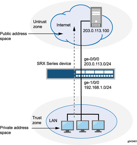
This example uses the trust security zone for the private address space and the untrust security zone for the public address space. In Figure 1, devices with private addresses in the trust zone access a public network through the egress interface ge-0/0/0. For packets that enter the Juniper Networks security device from the trust zone with a destination address in the untrust zone, the source IP address is translated to the IP address of the egress interface.
No source NAT pool is required for source NAT using an egress interface. Proxy ARP does not need to be configured for the egress interface.
This example describes the following configurations:
Source NAT rule set
rs1with a ruler1to match any packet from the trust zone to the untrust zone. For matching packets, the source address is translated to the IP address of the egress interface.Security policies to permit traffic from the trust zone to the untrust zone.
Configuration
Procedure
CLI Quick Configuration
To quickly configure this example, copy the
following commands, paste them into a text file, remove any line breaks,
change any details necessary to match your network configuration,
copy and paste the commands into the CLI at the [edit] hierarchy
level, and then enter commit from configuration mode.
set security nat source rule-set rs1 from zone trust
set security nat source rule-set rs1 to zone untrust
set security nat source rule-set rs1 rule r1 match source-address 0.0.0.0/0
set security nat source rule-set rs1 rule r1 match destination-address 0.0.0.0/0
set security nat source rule-set rs1 rule r1 then source-nat interface
set security policies from-zone trust to-zone untrust policy internet-access match source-address any
set security policies from-zone trust to-zone untrust policy internet-access match destination-address any
set security policies from-zone trust to-zone untrust policy internet-access match application any
set security policies from-zone trust to-zone untrust policy internet-access then permit
Step-by-Step Procedure
The following example requires you to navigate throughout various levels in the configuration hierarchy. For instructions on how to do that, see Using the CLI Editor in Configuration Mode.
To configure a source NAT translation to an egress interface:
Create a source NAT rule set.
[edit security nat source]
user@host# set rule-set rs1 from zone trust
user@host# set rule-set rs1 to zone untrust
Configure a rule that matches packets and translates the source address to the address of the egress interface.
[edit security nat source]
user@host# set rule-set rs1 rule r1 match source-address 0.0.0.0/0
user@host# set rule-set rs1 rule r1 match destination-address 0.0.0.0/0
user@host# set rule-set rs1 rule r1 then source-nat interface
Configure a security policy that allows traffic from the trust zone to the untrust zone.
[edit security policies from-zone trust to-zone untrust]
user@host# set policy internet-access match source-address any destination-address any application any
user@host# set policy internet-access then permit
Results
From configuration mode, confirm your configuration
by entering the show security nat and show security
policies commands. If the output does not display the intended
configuration, repeat the configuration instructions in this example
to correct it.
[edit]
user@host# show security nat
source {
    rule-set rs1 {
        from zone trust;
        to zone untrust;
        rule r1 {
            match {
                source-address 0.0.0.0/0;
                destination-address 0.0.0.0/0;
            }
            then {
                source-nat {
                    interface;
                }
            }
        }
    }
}
user@host# show security policies
from-zone trust to-zone untrust {
    policy internet-access {
        match {
            source-address any;
            destination-address any;
            application any;
        }
        then {
            permit;
        }
    }
}
If you are done configuring the device, enter commit from configuration mode.
Verification
To confirm that the configuration is working properly, perform these tasks:
Verifying Source NAT Rule Usage
Purpose
Verify that there is traffic matching the source NAT rule.
Action
From operational mode, enter the show security nat source
rule all command. View the Translation hits field to check for
traffic that matches the rule.
Example: Configuring Source NAT for Single Address Translation
This example describes how to configure a source NAT mapping of a single private address to a public address.
Requirements
Before you begin:
Configure network interfaces on the device. See Interfaces User Guide for Security Devices.
Create security zones and assign interfaces to them. See Understanding Security Zones.
Overview
This example uses the trust security zone for the private address space and the untrust security zone for the public address space. In Figure 2, a device with the private address 192.168.1.200 in the trust zone accesses a public network. For packets sent by the device to a destination address in the untrust zone, the Juniper Networks security device translates the source IP address to the public IP address 203.0.113.200/32.
This example describes the following configurations:
Source NAT pool
src-nat-pool-1that contains the IP address 203.0.113.200/32.Source NAT rule set
rs1with ruler1to match packets from the trust zone to the untrust zone with the source IP address 192.168.1.200/32. For matching packets, the source address is translated to the IP address insrc-nat-pool-1pool.Proxy ARP for the address 203.0.113.200 on interface ge-0/0/0.0. This allows the Juniper Networks security device to respond to ARP requests received on the interface for that address.
Security policies to permit traffic from the trust zone to the untrust zone.
Configuration
Procedure
CLI Quick Configuration
To quickly configure this example, copy the
following commands, paste them into a text file, remove any line breaks,
change any details necessary to match your network configuration,
copy and paste the commands into the CLI at the [edit] hierarchy
level, and then enter commit from configuration mode.
set security nat source pool src-nat-pool-1 address 203.0.113.200/32 set security nat source rule-set rs1 from zone trust set security nat source rule-set rs1 to zone untrust set security nat source rule-set rs1 rule r1 match source-address 192.168.1.200/32 set security nat source rule-set rs1 rule r1 then source-nat pool src-nat-pool-1 set security nat proxy-arp interface ge-0/0/0.0 address 203.0.113.200/32 set security policies from-zone trust to-zone untrust policy internet-access match source-address any set security policies from-zone trust to-zone untrust policy internet-access match destination-address any set security policies from-zone trust to-zone untrust policy internet-access match application any set security policies from-zone trust to-zone untrust policy internet-access then permit
Step-by-Step Procedure
The following example requires you to navigate throughout various levels in the configuration hierarchy. For instructions on how to do that, see Using the CLI Editor in Configuration Mode.
To configure a source NAT translation for a single IP address:
Create a source NAT pool.
[edit security nat source] user@host# set pool src-nat-pool-1 address 203.0.113.200/32
Create a source NAT rule set.
[edit security nat source] user@host# set rule-set rs1 from zone trust user@host# set rule-set rs1 to zone untrust
Configure a rule that matches packets and translates the source address to the address in the pool.
[edit security nat source] user@host# set rule-set rs1 rule r1 match source-address 192.168.1.200/32 user@host# set rule-set rs1 rule r1 then source-nat pool src-nat-pool-1
Configure proxy ARP.
[edit security nat] user@host# set proxy-arp interface ge-0/0/0.0 address 203.0.113.200
Configure a security policy that allows traffic from the trust zone to the untrust zone.
[edit security policies from-zone trust to-zone untrust] user@host# set policy internet-access match source-address any destination-address any application any user@host# set policy internet-access then permit
Results
From configuration mode, confirm your configuration
by entering the show security nat and show security
policies commands. If the output does not display the intended
configuration, repeat the configuration instructions in this example
to correct it.
[edit]
user@host# show security nat
source {
pool src-nat-pool-1 {
address {
203.0.113.200/32;
}
}
rule-set rs1 {
from zone trust;
to zone untrust;
rule r1 {
match {
source-address 192.168.1.200/32;
}
then {
source-nat {
pool {
src-nat-pool-1;
}
}
}
}
}
}
proxy-arp {
interface ge-0/0/0.0 {
address {
203.0.113.200/32;
}
}
}
user@host# show security policies
from-zone trust to-zone untrust {
policy internet-access {
match {
source-address any;
destination-address any;
application any;
}
then {
permit;
}
}
}
If you are done configuring the device, enter commit from configuration mode.
Verification
To confirm that the configuration is working properly, perform these tasks:
- Verifying Source NAT Pool Usage
- Verifying Source NAT Rule Usage
- Verifying NAT Application to Traffic
Verifying Source NAT Pool Usage
Purpose
Verify that there is traffic using IP addresses from the source NAT pool.
Action
From operational mode, enter the show security nat source
pool all command. View the Translation hits field to check for
traffic using IP addresses from the pool.
Verifying Source NAT Rule Usage
Purpose
Verify that there is traffic matching the source NAT rule.
Action
From operational mode, enter the show security nat source
rule all command. View the Translation hits field to check for
traffic that matches the rule.
Example: Configure MAP-E on SRX Series Firewalls
Use this configuration example to configure Mapping of Address and Port with Encapsulation (MAP-E) functionality on SRX Series Firewalls.
|
Reading Time |
Less than an hour |
|
Configuration Time |
Less than an hour |
- Example Prerequisites
- Before You Begin
- Functional Overview
- Topology Overview
- Topology Illustration
- Step-By-Step Configuration on SRX Series Firewall as a MAP-E CE Device
- Step-By-Step Configuration on MX Series Device as a BR Device
- Verification
- Appendix 1: Set Commands on All Devices
- Appendix 2: Show Configuration Output on All Devices
Example Prerequisites
|
Hardware requirements |
Juniper Networks® SRX1500 Firewall or lower-numbered device models or Juniper Networks® vSRX Virtual Firewall (vSRX3.0) |
|
Software requirements |
Junos OS Release 19.4R1 or later. |
Before You Begin
|
Benefits |
|
|
Know more |
Understanding Mapping of Address and Port with Encapsulation (MAP-E) |
|
Hands-on experience |
vLab Sandbox: NAT - Source & Destination |
|
Learn more |
Configuring MAP-E on NFX Series DevicesUnderstanding Mapping of Address and Port with Encapsulation (MAP-E)Mapping of Address and Port with Encapsulation (MAP-E) for Next Gen Services |
Functional Overview
MAP-E transports IPv4 packets across an IPv6 network. A MAP-E network contains two types of devices:
-
MAP-E Customer Edge (CE): These dual-stacked CE devices support both IPv4 and IPv6. They can also perform Network Address Port Translation (NAPT).
-
MAP-E Border Relay (BR): The CE device connects a private IPv4 host and a BR device across an IPv6-only network domain.
Table 6 provides a quick summary of the configuration components deployed in this example.
|
Technologies used |
|
|
Primary verification tasks |
After completing the MAP-E configuration on an SRX Series Firewall, you can verify the status of the MAP-E configuration. |
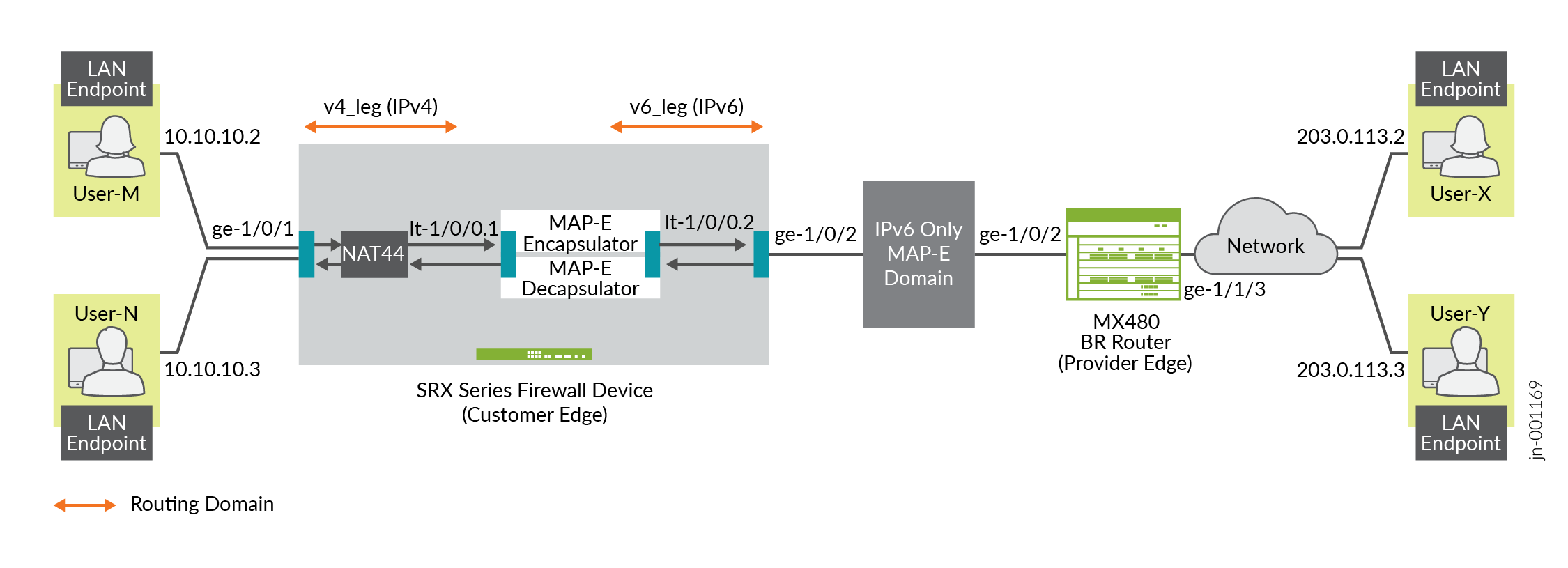
Topology Overview
This topology presents the configuration process for MAP-E CE functionality on SRX Series Firewall devices. It also depicts the encapsulation and transport of IPv4 packets originating from MAP-E CE devices. The configuration moves these packets through an IPv4-over-IPv6 tunnel to MAP-E PE and BR devices. The packets then undergo detunneling in an IPv6 routing topology for further processing. A dual-stack MX Series device, connected to both a public IPv4 network and an IPv6 MAP-E network, serves as the MAP-E BR device.
|
Hostname |
Role |
Function |
|---|---|---|
|
LAN end-point |
End-user network devices. |
Connects to the IPv4 network. |
|
SRX Series Firewall |
Connects the BR router and end user network devices. |
Supports connectivity to a large number of IPv4 subscribers over the ISP IPv6 access network. |
|
BR router |
Connects the IPv4 network and SRX Series Firewall device. |
A BR device has at least an IPv6-enabled interface and an IPv4 interface connected to the native IPv4 network. |
Topology Illustration
Step-By-Step Configuration on SRX Series Firewall as a MAP-E CE Device
For complete sample configurations on the DUT, see:
Step-By-Step Configuration on MX Series Device as a BR Device
To configure an MX Series device as a BR device:
Verification
This section provides a list of show commands that you can use to verify the feature in this example.
You must establish an SSH session on end devices to generate CLI output.
|
Command |
Verification Task |
|---|---|
show security flow session |
|
show security softwires map-e domain
mapce1 |
Verify the MAP-E Domain |
show security nat source rule all |
|
show security nat source pool all |
|
show security nat source summary |
|
show security nat source persistent-nat-table
all
|
|
show services inline softwire statistics
mape |
- Verify the Flow Session
- Verify the MAP-E Domain
- Verify the NAT Source Rule
- Verify the NAT Source Pool
- Verify the NAT Source Summary
- Verify the Persistent NAT Table
- Verify the Softwire Statistics on the MX Series Device
Verify the Flow Session
Purpose
Verify the packet flow session.
Action
From operational mode, enter the show security flow session
command to view the packet flow.
user@srx> show security flow session Session ID: 134218806, Policy name: my_ce/4, Timeout: 1800, Valid In: 10.10.10.2/57630 --> 203.0.113.2/22;tcp, Conn Tag: 0x0, If: ge-1/0/1.0, Pkts: 50, Bytes: 5797, Out: 203.0.113.2/22 --> 192.0.2.18/20691;tcp, Conn Tag: 0x0, If: lt-1/0/0.1, Pkts: 33, Bytes: 5697, Session ID: 134218807, Policy name: my_ce/4, Timeout: 1800, Valid In: 2001:db8:12:3400:c0:2:1200:3400/1 --> 2001:db8::a/1;ipip, Conn Tag: 0x0, If: lt-1/0/0.2, Pkts: 50, Bytes: 7797, Out: 2001:db8::a/1 --> 2001:db8:12:3400:c0:2:1200:3400/1;ipip, Conn Tag: 0x0, If: ge-1/0/2.0, Pkts: 33, Bytes: 7017, Total sessions: 2
Meaning
The sample output confirms the packet flow session are up.
Verify the MAP-E Domain
Purpose
Verify whether the IPv4 and IPv6 addresses are configured correctly.
Action
From operational mode, enter the show security softwires map-e domain
mapce1 command to view the IPv4 and IPv6 addresses.
user@srx> show security softwires map-e domain mapce1
Role : CE
Version : 3
Domain Name : mapce1
BR Address : 2001:db8::a/128
End User Ipv6 prefix : 2001:db8:12:3400::/56
BMR Mapping Rule :
Rule Name : bmr
Rule Ipv4 Prefix : 192.0.2.0/24
Rule Ipv6 Prefix : 2001:db8::/40
PSID offset : 6
PSID length : 8
EA bit length : 16
Port SetID : 0x34
MAP-E Ipv4 address : 192.0.2.18/32
MAP-E Ipv6 address : 2001:db8:12:3400:c0:2:1200:3400
Meaning
The sample output displays the configured IPv4 and IPv6 addresses.
Verify the NAT Source Rule
Purpose
View details of the NAT source rule.
Action
From operational mode, enter the show security nat source rule
all command to view the NAT source rules.
user@srx> show security nat source rule all
Total rules: 1
Total referenced IPv4/IPv6 ip-prefixes: 5/0
source NAT rule: r1
Rule-set : mape
Rule-Id : 1
Rule position : 1
From zone : v4zone
To interface : lt-1/0/0.1
: ge-1/0/1.0
Match
Source addresses : 10.10.10.0 - 10.10.10.255
Destination addresses : 10.10.10.0 - 10.10.10.255
198.51.100.0 - 198.51.100.255
203.0.113.0 - 203.0.113.255
192.0.2.0 - 192.0.2.255
Action : my_mape
Persistent NAT type : any-remote-host
Persistent NAT mapping type : address-port-mapping
Inactivity timeout : 300
Max session number : 30
Translation hits : 1
Successful sessions : 1
Failed sessions : 0
Number of sessions : 1
Meaning
The sample output displays the configured NAT source rules.
Verify the NAT Source Pool
Purpose
View details of the NAT source pool.
Action
From operational mode, enter the show security nat source pool
all command to view the NAT source pool.
user@srx> show security nat source pool all
Total pools: 1
Pool name : my_mape
Pool id : 4
Routing instance : default
Host address base : 0.0.0.0
Map-e domain name : mapce1
Map-e rule name : bmr
PSID offset : 6
PSID length : 8
PSID : 0x34
Port overloading : 1
Address assignment : no-paired
Total addresses : 1
Translation hits : 1
Address range Single Ports Twin Ports
192.0.2.18 - 192.0.2.18 1 0
Total used ports : 1 0
Meaning
The sample output displays the configured NAT source pool.
Verify the NAT Source Summary
Purpose
View the NAT source summary.
Action
From operational mode, enter the show security nat source
summary command to view the NAT source details.
user@srx> show security nat source summary
show security nat source summary
Total port number usage for port translation pool: 252
Maximum port number for port translation pool: 134217728
Total pools: 1
Pool Address Routing PAT Total
Name Range Instance Address
my_mape 192.0.2.18-192.0.2.18 default yes 1
Total rules: 1
Rule name : r1
Rule set : mape
Action : my_mape
From : v4zone To : lt-0/0/0.1
Rule name : r1
To : ge-0/0/7.0Meaning
The sample output displays the configured NAT source details.
Verify the Persistent NAT Table
Purpose
View the persistent NAT table.
Action
From operational mode, enter the show security nat source
persistent-nat-table all command to view the persistent NAT
table.
user@srx> show security nat source persistent-nat-table all Internal Reflective Source Type Left_time/ Curr_Sess_Num/ Source In_IP In_Port I_Proto Ref_IP Ref_Port R_Proto NAT Pool Conf_time Max_Sess_Num NAT Rule 10.10.10.2 57630 tcp 192.0.2.18 20691 tcp my_mape any-remote-host -/300 1/30 r1
Meaning
The sample output displays the persistent NAT table.
Verify the Softwire Statistics on the MX Series Device
Purpose
View the softwire statistics on the MX Series device.
Action
From operational mode, enter the show services inline softwire
statistics mape command to view the softwire statistics on the
MX Series device.
user@host> show services inline softwire statistics mape
Service PIC Name si-1/0/0
Control Plane Statistics
MAPE ICMPv6 echo requests to softwire concentrator 0
MAPE ICMPv6 echo responses from softwire concentrator 0
MAPE Dropped ICMPv6 packets to softwire concentrator 0
Data Plane Statistics (v6-to-v4) Packets Bytes
MAPE decaps 15034 1388760
MAPE ICMP decap errors 0 0
MAPE decap spoof errors 0 0
MAPE v6 reassembled 0 0
MAPE dropped v6 fragments 0 0
MAPE v6 unsupp protocol drops 0 0
Data Plane Statistics (v4-to-v6) Packets Bytes
MAPE encaps 149544 223527457
MAPE ICMP encap errors 0 0
MAPE v6 mtu errors 0 0
MAPE v4 reassembled 0 0
MAPE dropped v4 fragments 0 0
Meaning
The sample output displays the softwire statistics on the MX Series device.
Appendix 1: Set Commands on All Devices
Set command output on all devices.
Set Commands on MAP-E CE Device
set security policies global policy my_ce match source-address any set security policies global policy my_ce match destination-address any set security policies global policy my_ce match application any set security policies global policy my_ce then permit set security policies default-policy permit-all set security zones security-zone v4zone host-inbound-traffic system-services all set security zones security-zone v4zone host-inbound-traffic protocols all set security zones security-zone v4zone interfaces ge-1/0/1.0 set security zones security-zone v4zone interfaces lt-1/0/0.1 set security zones security-zone v6zone host-inbound-traffic system-services all set security zones security-zone v6zone host-inbound-traffic protocols all set security zones security-zone v6zone interfaces ge-1/0/2.0 set security zones security-zone v6zone interfaces lt-1/0/0.2 set interfaces ge-1/0/1 unit 0 family inet address 10.10.10.1/24 set interfaces ge-1/0/2 mtu 9192 set interfaces ge-1/0/2 unit 0 family inet6 address 2001:db8:ffff::1/64 set interfaces lt-1/0/0 mtu 9192 set interfaces lt-1/0/0 unit 1 encapsulation ethernet set interfaces lt-1/0/0 unit 1 peer-unit 2 set interfaces lt-1/0/0 unit 1 family inet address 172.16.100.1/24 set interfaces lt-1/0/0 unit 1 family inet6 address 2001:db8:fffe::1/64 set interfaces lt-1/0/0 unit 2 encapsulation ethernet set interfaces lt-1/0/0 unit 2 peer-unit 1 set interfaces lt-1/0/0 unit 2 family inet address 172.16.100.2/24 set interfaces lt-1/0/0 unit 2 family inet6 address 2001:db8:fffe::2/64 set routing-instances v4_leg routing-options rib v4_leg.inet.0 static route 198.51.100.0/24 next-hop 172.16.100.2 set routing-instances v4_leg routing-options rib v4_leg.inet.0 static route 203.0.113.0/24 next-hop 172.16.100.2 set routing-instances v4_leg routing-options rib v4_leg.inet.0 static route 192.0.2.0/24 next-hop 172.16.100.2 set routing-instances v4_leg instance-type virtual-router set routing-instances v4_leg interface lt-1/0/0.1 set routing-instances v4_leg interface ge-1/0/1.0 set routing-instances v6_leg routing-options rib v6_leg.inet.0 static route 10.10.10.0/24 next-hop 172.16.100.1 set routing-instances v6_leg routing-options rib v6_leg.inet6.0 static route 2001:db8::a/128 next-hop 2001:db8:ffff::9 set routing-instances v6_leg routing-options rib v6_leg.inet6.0 static route 2001:db8:0012:3500::/56 next-hop 2001:db8:ffff::2 set routing-instances v6_leg routing-options rib v6_leg.inet6.0 static route 2001:db8:0012:3400::/56 next-hop 2001:db8:fffe::1 set routing-instances v6_leg instance-type virtual-router set routing-instances v6_leg interface lt-1/0/0.2 set routing-instances v6_leg interface ge-1/0/2.0 set security softwires map-e mapce1 br-address 2001:db8::a/128 set security softwires map-e mapce1 end-user-prefix 2001:db8:0012:3400::/56 set security softwires map-e mapce1 rule bmr rule-type BMR set security softwires map-e mapce1 rule bmr ipv4-prefix 192.0.2.0/24 set security softwires map-e mapce1 rule bmr ipv6-prefix 2001:db8::/40 set security softwires map-e mapce1 rule bmr ea-bits-length 16 set security softwires map-e mapce1 rule bmr psid-offset 6 set security softwires map-e mapce1 role CE set security softwires map-e mapce1 version 3 set security nat source pool my_mape allocation-domain mapce1 set security nat source pool my_mape allocation-domain allocation-rule bmr set security nat source rule-set mape from zone v4zone set security nat source rule-set mape to interface lt-1/0/0.1 set security nat source rule-set mape to interface ge-1/0/1.0 set security nat source rule-set mape rule r1 match source-address 10.10.10.0/24 set security nat source rule-set mape rule r1 match destination-address 10.10.10.0/24 set security nat source rule-set mape rule r1 match destination-address 198.51.100.0/24 set security nat source rule-set mape rule r1 match destination-address 203.0.113.0/24 set security nat source rule-set mape rule r1 match destination-address 192.0.2.0/24 set security nat source rule-set mape rule r1 then source-nat pool my_mape set security nat source rule-set mape rule r1 then source-nat pool persistent-nat permit any-remote-host
Set Commands on BR Device
set services service-set ss1 softwire-rules sw-rule1 set services service-set ss1 next-hop-service inside-service-interface si-1/0/0.1 set services service-set ss1 next-hop-service outside-service-interface si-1/0/0.2 set services softwire softwire-concentrator map-e mape-domain-1 softwire-address 2001:db8::a set services softwire softwire-concentrator map-e mape-domain-1 ipv4-prefix 192.0.2.0/24 set services softwire softwire-concentrator map-e mape-domain-1 mape-prefix 2001:db8::/40 set services softwire softwire-concentrator map-e mape-domain-1 ea-bits-len 16 set services softwire softwire-concentrator map-e mape-domain-1 psid-offset 6 set services softwire softwire-concentrator map-e mape-domain-1 psid-length 8 set services softwire softwire-concentrator map-e mape-domain-1 mtu-v6 9192 set services softwire softwire-concentrator map-e mape-domain-1 version-03 set services softwire softwire-concentrator map-e mape-domain-1 v4-reassembly set services softwire softwire-concentrator map-e mape-domain-1 v6-reassembly set services softwire softwire-concentrator map-e mape-domain-1 disable-auto-route set services softwire rule sw-rule1 match-direction input set services softwire rule sw-rule1 term t1 then map-e mape-domain-1 set interfaces si-1/0/0 unit 1 family inet6 set interfaces si-1/0/0 unit 1 service-domain inside set interfaces si-1/0/0 unit 2 family inet set interfaces si-1/0/0 unit 2 service-domain outside set interfaces ge-1/1/2 mtu 9192 set interfaces ge-1/1/2 unit 0 family inet6 address 2001:db8:ffff::9/64 set interfaces ge-1/1/3 unit 0 family inet address 203.0.113.1/24 set routing-options rib inet6.0 static route 2001:db8::/40 next-hop si-1/0/0.1 set routing-options rib inet6.0 static route 2001:db8:0012:3400::/56 next-hop 2001:db8:ffff::1 set routing-options rib inet6.0 static route 2001:db8:0012:3500::/56 next-hop 2001:db8:ffff::2 set routing-options static route 192.0.2.0/24 next-hop si-1/0/0.2 set routing-options static route 198.51.100.0/24 next-hop si-1/0/0.2 set routing-options static route 203.0.113.0/24 next-hop si-1/0/0.2
Appendix 2: Show Configuration Output on All Devices
Show command output on all devices.
Show Commands on MAP-E CE Device
From configuration mode, confirm your configuration by entering the show
security policies, show security zones,
show interfaces, show routing-instances,
show security softwires, and show security nat
source commands. If the output does not display the intended
configuration, repeat the configuration instructions in this example to correct
it.
user@srx# show security policies
global {
policy my_ce {
match {
source-address any;
destination-address any;
application any;
}
then {
permit;
}
}
}
default-policy {
permit-all;
}user@srx# show security zones
security-zone v4zone {
host-inbound-traffic {
system-services {
all;
}
protocols {
all;
}
}
interfaces {
ge-1/0/1.0;
lt-1/0/0.1;
}
}
security-zone v6zone {
host-inbound-traffic {
system-services {
all;
}
protocols {
all;
}
}
interfaces {
ge-1/0/2.0;
lt-1/0/0.2;
}
}
user@srx# show interfaces
lt-1/0/0 {
mtu 9192;
unit 1 {
encapsulation ethernet;
peer-unit 2;
family inet {
address 172.16.100.1/24;
}
family inet6 {
address 2001:db8:fffe::1/64;
}
}
unit 2 {
encapsulation ethernet;
peer-unit 1;
family inet {
address 172.16.100.2/24;
}
family inet6 {
address 2001:db8:fffe::2/64;
}
}
}
ge-1/0/1 {
unit 0 {
family inet {
address 10.10.10.1/24;
}
}
}
ge-1/0/2 {
mtu 9192;
unit 0 {
family inet6 {
address 2001:db8:ffff::1/64;
}
}
}
user@srx# show routing-instances
v4_leg {
instance-type virtual-router;
routing-options {
rib v4_leg.inet.0 {
static {
route 192.0.2.0/24 next-hop 172.16.100.2;
route 198.51.100.0/24 next-hop 172.16.100.2;
route 203.0.113.0/24 next-hop 172.16.100.2;
}
}
}
interface lt-1/0/0.1;
interface ge-1/0/1.0;
}
v6_leg {
instance-type virtual-router;
routing-options {
rib v6_leg.inet.0 {
static {
route 10.10.10.0/24 next-hop 172.16.100.1;
}
}
rib v6_leg.inet6.0 {
static {
route 2001:db8::a/128 next-hop 2001:db8:ffff::9;
route 2001:db8:0012:3400::/56 next-hop 2001:db8:fffe::1;
route 2001:db8:0012:3500::/56 next-hop 2001:db8:ffff::2;
}
}
}
interface lt-1/0/0.2;
interface ge-1/0/2.0;
}
user@srx# show security softwires
map-e mapce1 {
br-address "$9$AodDuIEhSrlvWB1Yg4aiH.P5T/CEcyeWLz3EcyrvMaZGU.P"; ## SECRET-DATA
end-user-prefix {
2001:db8:0012:3400::/56;
}
rule bmr {
rule-type BMR;
ipv4-prefix "$9$WVnL-VJGDH.PY2P5z6CAvW8xdbwYgDikY2QF"; ## SECRET-DATA
ipv6-prefix "$9$O4LbISrlKMWX7hcaZGDmPTz3np0rev87-hcs2g4ZG"; ## SECRET-DATA
ea-bits-length 16; ## SECRET-DATA
psid-offset "$9$y8NeLx"; ## SECRET-DATA
}
role CE;
version 3;
}
user@srx# show security nat source
pool my_mape {
allocation-domain mapce1 allocation-rule bmr;
}
rule-set mape {
from zone v4zone;
to interface [ lt-1/0/0.1 ge-1/0/1.0 ];
rule r1 {
match {
source-address 10.10.10.0/24;
destination-address [ 10.10.10.0/24 198.51.100.0/24 203.0.113.0/24 192.0.2.0/24 ];
}
then {
source-nat {
pool {
my_mape;
persistent-nat {
permit any-remote-host;
}
}
}
}
}
}
Show Commands on BR Device
From configuration mode, confirm your configuration by entering the show
services, show interfaces, and show
routing-options commands. If the output does not display the
intended configuration, repeat the configuration instructions in this example to
correct it.
user@router# show services
service-set ss1 {
softwire-rules sw-rule1;
next-hop-service {
inside-service-interface si-1/0/0.1;
outside-service-interface si-1/0/0.2;
}
}
softwire {
softwire-concentrator {
map-e mape-domain-1 {
softwire-address 2001:db8::a;
ipv4-prefix 192.0.2.0/24;
mape-prefix 2001:db8::/40;
ea-bits-len 16;
psid-offset 6;
psid-length 8;
mtu-v6 9192;
version-03;
v4-reassembly;
v6-reassembly;
disable-auto-route;
}
}
rule sw-rule1 {
match-direction input;
term t1 {
then {
map-e mape-domain-1;
}
}
}
}user@router# show interfaces
lt-0/0/10 {
unit 0 {
encapsulation vlan-bridge;
vlan-id 10;
peer-unit 1;
}
}
si-1/0/0 {
unit 1 {
family inet6;
service-domain inside;
}
unit 2 {
family inet;
service-domain outside;
}
}
ge-1/1/2 {
mtu 9192;
unit 0 {
family inet6 {
address 2001:db8:ffff::9/64;
}
}
}
ge-1/1/3 {
unit 0 {
family inet {
address 203.0.113.1/24;
}
}
}
ge-1/3/11 {
unit 0 {
family inet {
address 10.0.1.2/30;
}
family mpls;
}
}
irb {
unit 0 {
family inet {
address 192.0.2.1/24;
}
}
}
lo0 {
apply-groups-except global;
unit 0 {
family inet {
address 10.255.0.2/32;
}
}
}user@router# show routing-options
rib inet6.0 {
static {
route 2001:db8::/40 next-hop si-1/0/0.1;
route 2001:db8:0012:3400::/56 next-hop 2001:db8:ffff::1;
route 2001:db8:0012:3500::/56 next-hop 2001:db8:ffff::2;
}
}
router-id 10.255.0.2;
autonomous-system 100;
static {
route 0.0.0.0/0 next-hop [ 10.102.70.254 10.10.0.0 ];
route 192.0.2.0/24 next-hop si-1/0/0.2;
route 198.51.100.0/24 next-hop si-1/0/0.2;
route 203.0.113.0/24 next-hop si-1/0/0.2;
}
forwarding-table {
chained-composite-next-hop {
ingress {
evpn;
}
}
}Example: Configuring Source and Destination NAT Translations
This example describes how to configure both source and destination NAT mappings.
Requirements
Before you begin:
Configure network interfaces on the device. See Interfaces User Guide for Security Devices.
Create security zones and assign interfaces to them. See Understanding Security Zones.
Overview
This example uses the trust security zone for the private address space and the untrust security zone for the public address space. In Figure 4, the following translations are performed on the Juniper Networks security device:
The source IP address in packets sent by the device with the private address 192.168.1.200 in the trust zone to any address in the untrust zone is translated to a public address in the range from 203.0.113.10 through 203.0.113.14.
The destination IP address 203.0.113.100/32 in packets sent from the trust zone to the untrust zone is translated to the address 10.1.1.200/32.
This example describes the following configurations:
Source NAT pool
src-nat-pool-1that contains the IP address range 203.0.113.10 through 203.0.113.14.Source NAT rule set
rs1with ruler1to match any packets from the trust zone to the untrust zone. For matching packets, the source address is translated to an IP address in thesrc-nat-pool-1pool.Destination NAT pool
dst-nat-pool-1that contains the IP address 10.1.1.200/32.Destination NAT rule set
rs1with ruler1to match packets from the trust zone with the destination IP address 203.0.113.100. For matching packets, the destination address is translated to the IP address in thedst-nat-pool-1pool.Proxy ARP for the addresses 203.0.113.10 through 203.0.113.14 and 203.0.113.100/32 on interface ge-0/0/0.0. This allows the Juniper Networks security device to respond to ARP requests received on the interface for those addresses.
Security policy to permit traffic from the trust zone to the untrust zone.
Security policy to permit traffic from the untrust zone to the translated destination IP addresses in the trust zone.
Configuration
Procedure
CLI Quick Configuration
To quickly configure this example, copy the
following commands, paste them into a text file, remove any line breaks,
change any details necessary to match your network configuration,
copy and paste the commands into the CLI at the [edit] hierarchy
level, and then enter commit from configuration mode.
set security nat source pool src-nat-pool-1 address 203.0.113.10/32 to 203.0.113.14/32 set security nat source rule-set rs1 from zone trust set security nat source rule-set rs1 to zone untrust set security nat source rule-set rs1 rule r1 match source-address 0.0.0.0/0 set security nat source rule-set rs1 rule r1 match destination-address 0.0.0.0/0 set security nat source rule-set rs1 rule r1 then source-nat pool src-nat-pool-1 set security nat destination pool dst-nat-pool-1 address 10.1.1.200/32 set security nat destination rule-set rs1 from zone untrust set security nat destination rule-set rs1 rule r1 match destination-address 203.0.113.100/32 set security nat destination rule-set rs1 rule r1 then destination-nat pool dst-nat-pool-1 set security nat proxy-arp interface ge-0/0/0.0 address 203.0.113.10/32 to 203.0.113.24/32 set security nat proxy-arp interface ge-0/0/0.0 address 203.0.113.100/32 set security policies from-zone trust to-zone untrust policy internet-access match source-address any set security policies from-zone trust to-zone untrust policy internet-access match destination-address any set security policies from-zone trust to-zone untrust policy internet-access match application any set security policies from-zone trust to-zone untrust policy internet-access then permit set security address-book global address dst-nat-pool-1 10.1.1.200/32 set security policies from-zone untrust to-zone trust policy dst-nat-pool-1-access match source-address any set security policies from-zone untrust to-zone trust policy dst-nat-pool-1-access match destination-address dst-nat-pool-1 set security policies from-zone untrust to-zone trust policy dst-nat-pool-1-access match application any set security policies from-zone untrust to-zone trust policy dst-nat-pool-1-access then permit
Step-by-Step Procedure
The following example requires you to navigate throughout various levels in the configuration hierarchy. For instructions on how to do that, see Using the CLI Editor in Configuration Mode.
To configure the source and destination NAT translations:
Create a source NAT pool.
[edit security nat source] user@host# set pool src-nat-pool-1 address 203.0.113.10 to 203.0.113.14
Create a source NAT rule set.
[edit security nat source]
user@host# set rule-set rs1 from zone trust
user@host# set rule-set rs1 to zone untrust
Configure a rule that matches packets and translates the source address to an address in the source NAT pool.
[edit security nat source] user@host# set rule-set rs1 rule r1 match source-address 0.0.0.0/0 user@host# set rule-set rs1 rule r1 match destination-address 0.0.0.0/0 user@host# set rule-set rs1 rule r1 then source-nat pool src-nat-pool-1
Create a destination NAT pool.
[edit security nat destination] user@host# set pool dst-nat-pool-1 address 10.1.1.200/32
Create a destination NAT rule set.
[edit security nat destination] user@host# set rule-set rs1 from zone untrust
Configure a rule that matches packets and translates the destination address to the address in the destination NAT pool.
[edit security nat destination] user@host# set rule-set rs1 rule r1 match destination-address 203.0.113.100/32 user@host# set rule-set rs1 rule r1 then destination-nat pool dst-nat-pool-1
Configure proxy ARP.
[edit security nat] user@host# set proxy-arp interface ge-0/0/0.0 address 203.0.113.10 to 203.0.113.14 user@host# set proxy-arp interface ge-0/0/0.0 address 203.0.113.100
Configure a security policy that allows traffic from the trust zone to the untrust zone.
[edit security policies from-zone trust to-zone untrust]
user@host# set policy internet-access match source-address any destination-address any application any
user@host# set policy internet-access then permit
Configure an address in the global address book.
[edit security address-book global] user@host# set address dst-nat-pool-1 10.1.1.200/32
Configure a security policy that allows traffic from the untrust zone to the trust zone.
[edit security policies from-zone untrust to-zone trust] user@host# set policy dst-nat-pool-1-access match source-address any destination-address dst-nat-pool-1 application any user@host# set policy dst-nat-pool-1-access then permit
Results
From configuration mode, confirm your configuration
by entering the show security nat and show security
policies commands. If the output does not display the intended
configuration, repeat the configuration instructions in this example
to correct it.
[edit]
user@host# show security nat
source {
pool src-nat-pool-1 {
address {
203.0.113.10/32 to 203.0.113.14/32;
}
}
rule-set rs1 {
to zone untrust;
rule r1 {
match {
source-address 0.0.0.0/0;
destination-address 0.0.0.0/0;
}
then {
source-nat {
pool {
src-nat-pool-1;
}
}
}
}
}
}
destination {
pool dst-nat-pool-1 {
address 10.1.1.200/32;
}
rule-set rs1 {
from zone untrust;
rule r1 {
match {
destination-address 203.0.113.100/32;
}
then {
destination-nat pool dst-nat-pool-1;
}
}
}
}
proxy-arp {
interface ge-0/0/0.0 {
address {
203.0.113.10/32 to 203.0.113.14/32;
203.0.113.100/32;
}
}
}
user@host# show security policies
from-zone trust to-zone untrust {
policy internet-access {
match {
source-address any;
destination-address any;
application any;
}
}
policy internet-access {
then {
permit;
}
}
}
from-zone untrust to-zone trust {
policy dst-nat-pool-1-access {
match {
source-address any;
destination-address dst-nat-pool-1;
application any;
}
then {
permit;
}
}
}
If you are done configuring the device, enter commit from configuration mode.
Verification
To confirm that the configuration is working properly, perform these tasks:
- Verifying Source NAT Pool Usage
- Verifying Source NAT Rule Usage
- Verifying Destination NAT Pool Usage
- Verifying Destination NAT Rule Usage
- Verifying NAT Application to Traffic
Verifying Source NAT Pool Usage
Purpose
Verify that there is traffic using IP addresses from the source NAT pool.
Action
From operational mode, enter the show security nat source
pool all command. View the Translation hits field to check for
traffic using IP addresses from the pool.
Verifying Source NAT Rule Usage
Purpose
Verify that there is traffic matching the source NAT rule.
Action
From operational mode, enter the show security nat source
rule all command. View the Translation hits field to check for
traffic that matches the rule.
Verifying Destination NAT Pool Usage
Purpose
Verify that there is traffic using IP addresses from the destination NAT pool.
Action
From operational mode, enter the show security nat destination
pool all command. View the Translation hits field to check for
traffic using IP addresses from the pool.
Verifying Destination NAT Rule Usage
Purpose
Verify that there is traffic matching the destination NAT rule.
Action
From operational mode, enter the show security nat destination
rule all command. View the Translation hits field to check for
traffic that matches the rule.
Understanding Source NAT Rules
Source NAT rules specify two layers of match conditions:
Traffic direction—Allows you to specify combinations of
from interface,from zone, orfrom routing-instanceandto interface,to zone, orto routing-instance. You cannot configure the samefromandtocontexts for different rule sets.Packet information—Can be source and destination IP addresses or subnets, source port numbers or port ranges, destination port numbers or port ranges, protocols, or applications.
For all ALG traffic, except FTP, we recommend that you not use
the source-port rule option. Data session creation can
fail if this option is used because the IP address and the source
port value, which is a random value, might not match the rule.
In addition, we recommend that you not use the destination-port option or the application option as matching conditions
for ALG traffic. If these options are used, translation may fail because
the port value in the application payload might not match the port
value in the IP address.
If multiple source NAT rules overlap in the match conditions, the most specific rule is chosen. For example, if rules A and B specify the same source and destination IP addresses, but rule A specifies traffic from zone 1 to zone 2 and rule B specifies traffic from zone 1 to interface ge-0/0/0, rule B is used to perform source NAT. An interface match is considered to be more specific than a zone match, which is more specific than a routing instance match.
The actions you can specify for a source NAT rule are:
off—Do not perform source NAT.
pool—Use the specified user-defined address pool to perform source NAT.
interface—Use the egress interface’s IP address to perform source NAT.
Source NAT rules are applied to traffic in the first packet that is processed for the flow or in the fast path for the ALG. Source NAT rules are processed after static NAT rules, destination NAT rules, and reverse mapping of static NAT rules and after route and security policy lookup.
When zones are not configured under rule-set and when active source NAT is configured with missing mandatory statement “from” then, the following message is displayed when performing commit “Missing mandatory statement: 'from' error: configuration check-out failed” and the configuration check-out fails.
Example: Configuring Source NAT with Multiple Rules
This example describes how to configure source NAT mappings with multiple rules.
Requirements
Before you begin:
Configure network interfaces on the device. See Interfaces User Guide for Security Devices.
Create security zones and assign interfaces to them. See Understanding Security Zones.
Overview
This example uses the trust security zone for the private address space and the untrust security zone for the public address space. In Figure 5, the following translations are performed on the Juniper Networks security device for the source NAT mapping for traffic from the trust zone to the untrust zones:
The source IP address in packets sent by the 10.1.1.0/24 and 10.1.2.0/24 subnets to any address in the untrust zone is translated to a public address in the range from 192.0.2.1 to 192.0.2.24 with port translation.
The source IP address in packets sent by the 192.168.1.0/24 subnet to any address in the untrust zone is translated to a public address in the range from 192.0.2.100 to 192.0.2.249 with no port translation.
The source IP address in packets sent by the 192.168.1.250/32 host device is not translated.
This example describes the following configurations:
Source NAT pool
src-nat-pool-1that contains the IP address range 192.0.2.1 through 192.0.2.24.Source NAT pool
src-nat-pool-2that contains the IP address range 192.0.2.100 through 192.0.2.249, with port address translation disabled.When port address translation is disabled, the number of translations that the source NAT pool can support concurrently is limited to the number of addresses in the pool, unless the
address-sharedoption is enabled. Packets are dropped if there are no addresses available in the source NAT pool. You can optionally specify an overflow pool from which IP addresses and port numbers are allocated when there are no addresses available in the original source NAT pool.Source NAT rule set
rs1to match packets from the trust zone to the untrust zone. Rule setrs1contains multiple rules:Rule
r1to match packets with a source IP address in either the 10.1.1.0/24 or 10.1.2.0/24 subnets. For matching packets, the source address is translated to an IP address in thesrc-nat-pool-1pool.Rule
r2to match packets with a source IP address of 192.168.1.250/32. For matching packets, there is no NAT translation performed.Rule
r3to match packets with a source IP address in the 192.168.1.0/24 subnet. For matching packets, the source address is translated to an IP address in thesrc-nat-pool-2pool.The order of rules in a rule set is important, as the first rule in the rule set that matches the traffic is used. Therefore, rule
r2to match a specific IP address must be placed before ruler3that matches the subnet on which the device is located.
Proxy ARP for the addresses 192.0.2.1 through 192.0.2.24 and 192.0.2.100 through 192.0.2.249 on interface ge-0/0/0.0. This allows the Juniper Networks security device to respond to ARP requests received on the interface for those addresses.
Security policies to permit traffic from the trust zone to the untrust zone.
When you configure source NAT rule or pool with rule name or pool name as interface or service-set you will receive the following error message: syntax error, expecting <data>.
If there is a source NAT rule named
interface, the rule cannot be viewed using theshow security nat source rule interfacecommand.If there is a source NAT rule named
service-set, the rule cannot be viewed using theshow security nat source rule service-setcommand.If there is a source NAT pool named
interface, the pool cannot be viewed using theshow security nat source pool interfacecommand.If there is a source NAT pool named
service-set, the pool cannot be viewed using theshow security nat source pool service-setcommand.If there is a source NAT pool named
interface, the paired-address cannot be viewed using theshow security nat source paired-address pool-name interfacecommand.If there is a source NAT pool named
service-set, the paired-address cannot be viewed using theshow security nat source paired-address pool-name service-setcommand.
Configuration
Procedure
CLI Quick Configuration
To quickly configure this example, copy the
following commands, paste them into a text file, remove any line breaks,
change any details necessary to match your network configuration,
copy and paste the commands into the CLI at the [edit] hierarchy
level, and then enter commit from configuration mode.
set security nat source pool src-nat-pool-1 address 192.0.2.1/32 to 192.0.2.24/32 set security nat source pool src-nat-pool-2 address 192.0.2.100/32 to 192.0.2.249/32 set security nat source pool src-nat-pool-2 port no-translation set security nat source rule-set rs1 from zone trust set security nat source rule-set rs1 to zone untrust set security nat source rule-set rs1 rule r1 match source-address 10.1.1.0/24 set security nat source rule-set rs1 rule r1 match source-address 10.1.2.0/24 set security nat source rule-set rs1 rule r1 match destination-address 0.0.0.0/0 set security nat source rule-set rs1 rule r1 then source-nat pool src-nat-pool-1 set security nat source rule-set rs1 rule r2 match source-address 192.168.1.250/32 set security nat source rule-set rs1 rule r2 match destination-address 0.0.0.0/0 set security nat source rule-set rs1 rule r2 then source-nat off set security nat source rule-set rs1 rule r3 match source-address 192.168.1.0/24 set security nat source rule-set rs1 rule r3 match destination-address 0.0.0.0/0 set security nat source rule-set rs1 rule r3 then source-nat pool src-nat-pool-2 set security nat proxy-arp interface ge-0/0/0.0 address 192.0.2.1/32 to 192.0.2.24/32 set security nat proxy-arp interface ge-0/0/0.0 address 192.0.2.100/32 to 192.0.2.249/32 set security policies from-zone trust to-zone untrust policy internet-access match source-address any set security policies from-zone trust to-zone untrust policy internet-access match destination-address any set security policies from-zone trust to-zone untrust policy internet-access match application any set security policies from-zone trust to-zone untrust policy internet-access then permit
Step-by-Step Procedure
The following example requires you to navigate throughout various levels in the configuration hierarchy. For instructions on how to do that, see Using the CLI Editor in Configuration Mode.
To configure multiple source NAT rules in a rule set:
Create a source NAT pool.
[edit security nat source] user@host# set pool src-nat-pool-1 address 192.0.2.1 to 192.0.2.24
Create a source NAT pool with no port translation.
[edit security nat source] user@host# set pool src-nat-pool-2 address 192.0.2.100 to 192.0.2.249 user@host# set pool src-nat-pool-2 port no-translation
To configure an overflow pool for
src-nat-pool-2using the egress interface:[edit security nat source] user@host# set pool src-nat-pool-2 overflow-pool interface
Create a source NAT rule set.
[edit security nat source]
user@host# set rule-set rs1 from zone trust
user@host# set rule-set rs1 to zone untrust
Configure a rule that matches packets and translates the source address to an address in the pool.
[edit security nat source] user@host# set rule-set rs1 rule r1 match source-address [10.1.1.0/24 10.1.2.0/24] user@host# set rule-set rs1 rule r1 match destination-address 0.0.0.0/0 user@host# set rule-set rs1 rule r1 then source-nat pool src-nat-pool-1
Configure a rule to match packets for which the source address is not translated.
[edit security nat source] user@host# set rule-set rs1 rule r2 match source-address 192.168.1.250/32 user@host# set rule-set rs1 rule r2 match destination-address 0.0.0.0/0 user@host# set rule-set rs1 rule r2 then source-nat off
Configure a rule to match packets and translate the source address to an address in the pool with no port translation.
[edit security nat source] user@host# set rule-set rs1 rule r3 match source-address 192.168.1.0/24 user@host# set rule-set rs1 rule r3 match destination-address 0.0.0.0/0 user@host# set rule-set rs1 rule r3 then source-nat pool src-nat-pool-2
Configure proxy ARP.
[edit security nat] user@host# set proxy-arp interface ge-0/0/0.0 address 192.0.2.1 to 192.0.2.24 user@host# set proxy-arp interface ge-0/0/0.0 address 192.0.2.100 to 192.0.2.249
Configure a security policy that allows traffic from the trust zone to the untrust zone.
[edit security policies from-zone trust to-zone untrust] user@host# set policy internet-access match source-address any destination-address any application any user@host# set policy internet-access then permit
Results
From configuration mode, confirm your configuration
by entering the show security nat and show security
policies commands. If the output does not display the intended
configuration, repeat the configuration instructions in this example
to correct it.
[edit]
user@host# show security nat
source {
pool src-nat-pool-1 {
address {
192.0.2.1/32 to 192.0.2.24/32;
}
}
pool src-nat-pool-2 {
address {
192.0.2.100/32 to 192.0.2.249/32;
}
port no-translation;
}
rule-set rs1 {
from zone trust;
to zone untrust;
rule r1 {
match {
source-address [ 10.1.1.0/24 10.1.2.0/24 ];
destination-address 0.0.0.0/0;
}
then {
source-nat {
pool {
src-nat-pool-1;
}
}
}
}
rule r2 {
match {
source-address 192.168.1.250/32;
destination-address 0.0.0.0/0;
}
then {
source-nat {
off;
}
}
}
rule r3 {
match {
source-address 192.168.1.0/24;
destination-address 0.0.0.0/0;
}
then {
source-nat {
pool {
src-nat-pool-2;
}
}
}
}
}
}
proxy-arp {
interface ge-0/0/0.0 {
address {
192.0.2.1/32 to 192.0.2.24/32;
192.0.2.100/32 to 192.0.2.249/32;
}
}
}
user@host# show security policies
from-zone trust to-zone untrust {
policy internet-access {
match {
source-address any;
destination-address any;
application any;
}
then {
permit;
}
}
}
If you are done configuring the device, enter commit from configuration mode.
Verification
To confirm that the configuration is working properly, perform these tasks:
- Verifying Source NAT Pool Usage
- Verifying Source NAT Rule Usage
- Verifying NAT Application to Traffic
Verifying Source NAT Pool Usage
Purpose
Verify that there is traffic using IP addresses from the source NAT pool.
Action
From operational mode, enter the show security nat source
pool all command. View the Translation hits field to check for
traffic using IP addresses from the pool.
Verifying Source NAT Rule Usage
Purpose
Verify that there is traffic matching the source NAT rule.
Action
From operational mode, enter the show security nat source
rule all command. View the Translation hits field to check for
traffic that matches the rule.
Understanding Source NAT Pools
A NAT pool is a user-defined set of IP addresses that are used for translation. Unlike static NAT, where there is a one-to-one mapping that includes destination IP address translation in one direction and source IP address translation in the reverse direction, with source NAT, you translate the original source IP address to an IP address in the address pool.
For source Network Address Translation (NAT) address pools, specify the following:
Name of the source NAT address pool.
-
Up to 64 address ranges.
Do not overlap NAT addresses for source NAT, destination NAT, and static NAT within one routing instance.
Routing instance—Routing instance to which the pool belongs (the default is the main inet.0 routing instance).
Port —The Port Address Translation (PAT) for a source pool. By default, PAT is performed with source NAT. If you specify the no-translation option, the number of hosts that the source NAT pool can support is limited to the number of addresses in the pool. If you specify
block-allocation, a block of ports is allocated for translation, instead of individual ports being allocated. If you specifydeterministic, an incoming (source) IP address and port always map to the specific destination address and port block, based on predefined, deterministic NAT algorithm. If you specifyport-overloading, you can configure the port overloading capacity in source NAT. If you specifyrange, you can provide the port number range attached to each address in the pool, and the twin port range for source NAT pools.Overflow pool (optional)—Packets are dropped if there are no addresses available in the designated source NAT pool. To prevent that from happening when the port no-translation option is configured, you can specify an overflow pool. Once addresses from the original source NAT pool are exhausted, IP addresses and port numbers are allocated from the overflow pool. A user-defined source NAT pool or an egress interface can be used as the overflow pool. (When the overflow pool is used, the pool ID is returned with the address.)
IP address shifting (optional)—A range of original source IP addresses can be mapped to another range of IP addresses, or to a single IP address, by shifting the IP addresses. Specify the host-address-base option with the base address of the original source IP address range.
Address sharing (optional)—Multiple internal IP addresses can be mapped to the same external IP address. This option can be used only when the source NAT pool is configured with no port translation. Specify the
address-sharedoption when a source NAT pool has few external IP addresses available, or only one external IP address. With a many-to-one mapping, use of this option increases NAT resources and improves traffic.Address pooling (optional)— Address pooling can be configured as paired or no-paired. Specify
address-pooling pairedfor applications that require all sessions associated with one internal IP address to be mapped to the same external IP address for the duration of a session. This differs from thepersistent-addressoption, in which the same internal address is translated to the same external address every time. Specifyaddress-pooling no-pairedfor applications that can be can be assigned IP addresses in a round-robin fashion. If eitheraddress-pooling pairedoraddress-pooling no-pairedis configured for a source NAT pool with PAT, the persistent address option is disabled. Ifaddress-sharedis configured on a source NAT pool without PAT, then thepersistent-addressoption is enabled. Bothaddress-sharedandaddress-pooling pairedcan be configured on the same source NAT pool without PAT.Pool utilization alarm (optional)— When the raise-threshold option is configured for source NAT, an SNMP trap is triggered if the source NAT pool utilization rises above this threshold. If the optional clear-threshold option is configured, an SNMP trap is triggered if the source NAT pool utilization drops below this threshold. If clear-threshold is not configured, it is set by default to 80 percent of the raise-threshold value.
You can use the show security nat resource usage source pool command to view address use in a source NAT pool without PAT, and to view port use in a source NAT pool with PAT.
Understanding Source NAT Pool Capacities
Increasing the total number of IP addresses used for source NAT, either by increasing the number of pools in the configuration and/or by increasing the capacity or IP-addresses per pool, consumes memory needed for port allocation. When source NAT pool and IP address limits are reached, port ranges should be reassigned. That is, the number of ports for each IP address should be decreased when the number of IP addresses and source NAT pools is increased. This ensures NAT does not consume too much memory.
See the Additional Platform Information section for more information.
Use Feature Explorer to confirm platform and release support for specific features. Additional platforms may be supported.
Use the range and range twin-port options
at the [edit security nat source pool port] hierarchy level
to assign a new port range or twin port range for a specific pool.
Use the pool-default-port-range and the pool-default-twin-port-range options at the [edit security nat source] hierarchy level
to specify the global default port range or twin port range for all
source NAT pools.
Configuring port overloading should also be done carefully when source NAT pools are increased.
For a source pool with PAT in range (63,488 through 65,535), two ports are allocated at one time for RTP/RTCP applications, such as SIP, H.323, and RTSP. In these scenarios, each IP address supports PAT, occupying 2048 ports (63,488 through 65,535) for ALG module use.
Understanding Persistent Addresses for Source NAT Pools
By default, port address translation is performed with source
NAT. However, an original source address may not be translated to
the same IP address for different traffic that originates from the
same host. The source NAT address-persistent option ensures
that the same IP address is assigned from the source NAT pool to a
specific host for multiple concurrent sessions.
This option differs from the address-pooling paired option, where the internal address is mapped to an external address within the pool on a first-come, first-served basis, and might be mapped to a different external address for each session.
Example: Configuring Capacity for Source NAT Pools with PAT
This example describes how to configure the capacity of source NAT pools with Port Address Translation (PAT) if a default port range is not set or you want to override it. Translations are set for each IP address. When the source pool is increased, ports should be reassigned if the current port number exceeds limitations.
Requirements
Before you begin:
Configure network interfaces on the device. See Interfaces User Guide for Security Devices.
Create security zones and assign interfaces to them. See Understanding Security Zones.
Overview
This example shows how to configure a PAT pool of 2048 IP addresses with 32,000 ports for each IP address.
Configuration
Procedure
CLI Quick Configuration
To quickly configure this example, copy the
following commands, paste them into a text file, remove any line breaks,
change any details necessary to match your network configuration,
copy and paste the commands into the CLI at the [edit] hierarchy
level, and then enter commit from configuration mode.
[edit security nat source] set pool src-nat-pat-addr address 192.168.0.0/32 to 192.168.3.255/32 set pool src-nat-pat-addr address 192.168.4.0/32 to 192.168.7.255/32 set pool-default-port-range 2001 set pool-default-port-range to 32720
Step-by-Step Procedure
The following example requires you to navigate throughout various levels in the configuration hierarchy. For instructions on how to do that, see Using the CLI Editor in Configuration Mode.
To configure capacity for a source NAT pool with PAT:
Specify a source NAT pool with PAT and an IP address range.
[edit security nat source] user@host# set pool src-nat-pat-addr address 192.168.0.0/32 to 192.168.3.255/32 user@host#set pool src-nat-pat-addr address 192.168.4.0/32 to 192.168.7.255/32
Specify a default port range for the source pool.
[edit security nat source] user@host# set pool-default-port-range 2001 user@host# set pool-default-port-range to 32720
Results
From configuration mode, confirm your configuration
by entering the show security nat-source-summary command.
If the output does not display the intended configuration, repeat
the configuration instructions in this example to correct it.
user@host> run show security nat source summary Total port number usage for port translation pool: 16515072 Maximum port number for port translation pool: 134217728 Total pools: 1 Pool Address Routing PAT Total Name Range Instance Address pool2 203.0.113.1 - 203.0.113.3 default yes 2048 Name Range Instance Address pool1 198.51.100.0 - 198.51.100.255 default yes 256 Total rules: 1 Rule name Rule set From To Action rule 1 ruleset1 ge-2/2/2.0 ge-2/2/3.0 pool1 rule 1 ge-2/2/4.0 ge-2/2/5.0
If you are done configuring the device, enter commit from configuration mode.
Verification
Verifying Capacity of Source NAT Pools
Purpose
View port and pool information. Port limitations are automatically checked, so the configuration will not be committed if port limitations are exceeded.
Action
From operational mode, enter the show security
nat source summary command to view port and pool details.
Understanding Source NAT Pools with Address Pooling
When a host initiates several sessions that match a policy that requires NAT, and is assigned an IP address from a source pool that has port address translation enabled, a different source IP address is used for each session.
Because some applications require the same source IP address
for each session, you can use the address-pooling paired feature to enable all sessions associated with one internal IP address
to map to the same external IP address for the duration of the sessions.
When the sessions end, the mapping between the internal IP address
and the external IP address ceases. The next time the host initiates
a session, a different IP address from the pool might be assigned
to it.
This differs from the source NAT address-persistent feature, which keeps the mapping static; the same internal IP address
is mapped to the same external IP address every time. It also differs
from the address-persistent feature in that address-pooling
paired is configured for a specific pool. The address-persistent feature is a global configuration that applies to all source pools.
Understanding Source NAT Pools with Address Shifting
The match conditions for a source NAT rule set do not allow
you to specify an address range; only address prefixes may be specified
in a rule. When configuring a source NAT pool, you can specify the host-base-address option; this option specifies the IP address
where the original source IP address range begins.
The range of original source IP addresses that are translated is determined by the number of addresses in the source NAT pool. For example, if the source NAT pool contains a range of ten IP addresses, then up to ten original source IP addresses can be translated, starting with a specified base address. This type of translation is one-to-one, static, and without port address translation.
The match condition in a source NAT rule may define a larger address range than that specified in the source NAT pool. For example, a match condition might specify an address prefix that contains 256 addresses, but the source NAT pool might contain a range of only a few IP addresses, or only one IP address. A packet’s source IP address can match a source NAT rule, but if the source IP address is not within the address range specified in the source NAT pool, the source IP address is not translated.
Example: Configuring Source NAT Pools with Address Shifting
This example describes how to configure a source NAT mapping of a private address range to public addresses, with optional address shifting. This mapping is one-to-one between the original source IP addresses and translated IP addresses.
The match conditions for a source NAT rule set do not allow you to specify an address
range; only address prefixes may be specified in a rule. When configuring a source NAT
pool, you can specify the host-base-address option; this option
specifies the IP address where the original source IP address range begins, and disables
port translation.
The range of original source IP addresses that are translated is determined by the number of addresses in the source NAT pool. For example, if the source NAT pool contains a range of ten IP addresses, then up to ten original source IP addresses can be translated, starting with a specified base address.
The match condition in a source NAT rule may define a larger address range than that specified in the source NAT pool. For example, a match condition might specify an address prefix that contains 256 addresses, but the source NAT pool contains a range of only ten IP addresses. A packet’s source IP address can match a source NAT rule, but if the source IP address is not within the address range specified in the source NAT pool, the source IP address is not translated.
Requirements
Before you begin:
Configure network interfaces on the device. See Interfaces User Guide for Security Devices.
Create security zones and assign interfaces to them. See Understanding Security Zones.
Overview
This example uses the trust security zone for the private address space and the untrust security zone for the public address space. In Figure 6, a range of private addresses in the trust zone is mapped to a range of public addresses in the untrust zone. For packets sent from the trust zone to the untrust zone, a source IP address in the range of 192.168.1.10/32 through 192.168.1.20/32 is translated to a public address in the range of 203.0.113.30/32 through 203.0.113.40/32.
This example describes the following configurations:
Source NAT pool
src-nat-pool-1that contains the IP address range 203.0.113.30/32 through 203.0.113.40/32. For this pool, the beginning of the original source IP address range is 192.168.1.10/32 and is specified with thehost-address-baseoption.Source NAT rule set
rs1with ruler1to match packets from the trust zone to the untrust zone with a source IP address in the 192.168.1.0/24 subnet. For matching packets that fall within the source IP address range specified by thesrc-nat-pool-1configuration, the source address is translated to the IP address insrc-nat-pool-1pool.Proxy ARP for the addresses 203.0.113.30/32 through 203.0.113.40/32 on interface ge-0/0/0.0. This allows the Juniper Networks security device to respond to ARP requests received on the interface for that address.
Security policies to permit traffic from the trust zone to the untrust zone.
Configuration
Procedure
CLI Quick Configuration
To quickly configure this example, copy the
following commands, paste them into a text file, remove any line breaks,
change any details necessary to match your network configuration,
copy and paste the commands into the CLI at the [edit] hierarchy
level, and then enter commit from configuration mode.
set security nat source pool src-nat-pool-1 address 203.0.113.30/32 to 203.0.113.40/32 set security nat source pool src-nat-pool-1 host-address-base 192.168.1.10/32 set security nat source rule-set rs1 from zone trust set security nat source rule-set rs1 to zone untrust set security nat source rule-set rs1 rule r1 match source-address 192.168.1.0/24 set security nat source rule-set rs1 rule r1 then source-nat pool src-nat-pool-1 set security nat proxy-arp interface ge-0/0/0.0 address 203.0.113.30/32 to 203.0.113.40/32 set security policies from-zone trust to-zone untrust policy internet-access match source-address any set security policies from-zone trust to-zone untrust policy internet-access match destination-address any set security policies from-zone trust to-zone untrust policy internet-access match application any set security policies from-zone trust to-zone untrust policy internet-access then permit
Step-by-Step Procedure
The following example requires you to navigate throughout various levels in the configuration hierarchy. For instructions on how to do that, see Using the CLI Editor in Configuration Mode.
To configure a source NAT mapping with address shifting:
Create a source NAT pool.
[edit security nat source] user@host# set pool src-nat-pool-1 address 203.0.113.30/32 to 203.0.113.40/32
Specify the beginning of the original source IP address range.
[edit security nat source] user@host# set pool src-nat-pool-1 host-address-base 192.168.1.10/32
Create a source NAT rule set.
[edit security nat source] user@host# set rule-set rs1 from zone trust user@host# set rule-set rs1 to zone untrust
Configure a rule that matches packets and translates the source address to an address in the pool.
[edit security nat source] user@host# set rule-set rs1 rule r1 match source-address 192.168.1.0/24 user@host# set rule-set rs1 rule r1 then source-nat pool src-nat-pool-1
Configure proxy ARP.
[edit security nat] user@host# set proxy-arp interface ge-0/0/0.0 address 203.0.113.30/32 to 203.0.113.40/32
Configure a security policy that allows traffic from the trust zone to the untrust zone.
[edit security policies from-zone trust to-zone untrust] user@host# set policy internet-access match source-address any destination-address any application any user@host# set policy internet-access then permit
Results
From configuration mode, confirm your configuration
by entering the show security nat and show security
policies commands. If the output does not display the intended
configuration, repeat the configuration instructions in this example
to correct it.
[edit]
user@host# show security nat
source {
pool src-nat-pool-1 {
address {
203.0.113.30/32 to 203.0.113.40/32;
}
host-address-base 192.168.1.10/32;
}
rule-set rs1 {
from zone trust;
to zone untrust;
rule r1 {
match {
source-address 192.168.1.0/24;
}
then {
source-nat {
pool {
src-nat-pool-1;
}
}
}
}
}
}
proxy-arp {
interface ge-0/0/0.0 {
address {
203.0.113.30/32 to 203.0.113.40/32;
}
}
}
user@host# show security policies
from-zone trust to-zone untrust {
policy internet-access {
match {
source-address any;
destination-address any;
application any;
}
then {
permit;
}
}
}
If you are done configuring the device, enter commit from configuration mode.
Verification
To confirm that the configuration is working properly, perform these tasks:
- Verifying Source NAT Pool Usage
- Verifying Source NAT Rule Usage
- Verifying NAT Application to Traffic
Verifying Source NAT Pool Usage
Purpose
Verify that there is traffic using IP addresses from the source NAT pool.
Action
From operational mode, enter the show security nat source
pool all command. View the Translation hits field to check for
traffic using IP addresses from the pool.
Verifying Source NAT Rule Usage
Purpose
Verify that there is traffic matching the source NAT rule.
Action
From operational mode, enter the show security nat source
rule all command. View the Translation hits field to check for
traffic that matches the rule.
Understanding Source NAT Pools with PAT
Using the source pool with Port Address Translation (PAT), Junos OS translates both the source IP address and the port number of the packets. When PAT is used, multiple hosts can share the same IP address.
Junos OS maintains a list of assigned port numbers to distinguish what session belongs to which host. When PAT is enabled, up to 63,488 hosts can share a single IP address. Each source pool can contain multiple IP addresses, multiple IP address ranges, or both. For a source pool with PAT, Junos OS may assign different addresses to a single host for different concurrent sessions, unless the source pool or Junos OS has the persistent address feature or the paired address pooling feature enabled.
For interface source pool and source pool with PAT, range (1024, 65535) is available for port number mapping per IP address. Within range (1024, 63487) one port is allocated at a time, for a total of 62,464 ports. In range (63488, 65535), two ports are allocated at a time for RTP/RTCP applications such as SIP, H.323, and RTSP, for a total of 2,048 ports.
When a host initiates several sessions that match a policy that requires network address translation and is assigned an address from a source pool that has PAT enabled, the device assigns a different source IP address for each session. Such random address assignment can be problematic for services that create multiple sessions that require the same source IP address for each session. For example, it is important to have the same IP address for multiple sessions when using the AOL Instant Message (AIM) client.
To ensure that the router assigns the same IP address from a source pool to a host for multiple concurrent sessions, you can enable a persistent IP address per router. To ensure that the device assigns the same IP address from a source pool to a host for the duration of a single session, you can enable paired address pooling.
Example: Configuring Source NAT for Multiple Addresses with PAT
This example describes how to configure a source NAT mapping of a private address block to a smaller public address block using port address translation.
Requirements
Before you begin:
Configure network interfaces on the device. See Interfaces User Guide for Security Devices.
Create security zones and assign interfaces to them. See Understanding Security Zones.
Overview
This example uses the trust security zone for the private address space and the untrust security zone for the public address space. In Figure 7, the source IP address in packets sent from the trust zone to the untrust zone is mapped to a smaller block of public addresses in the range from 203.0.113.1/32 through 203.0.113.24/32. Because the size of the source NAT address pool is smaller than the number of potential addresses that might need to be translated, port address translation is used.
Port address translation includes a source port number with the source IP address mapping. This allows multiple addresses on a private network to map to a smaller number of public IP addresses. Port address translation is enabled by default for source NAT pools.
This example describes the following configurations:
Source NAT pool
src-nat-pool-1that contains the IP address range 203.0.113.1/32 through 203.0.113.24/32.Source NAT rule set
rs1to match all packets from the trust zone to the untrust zone. For matching packets, the source IP address is translated to an IP address in thesrc-nat-pool-1pool.Proxy ARP for the addresses 203.0.113.1/32 through 203.0.113.24/32 on interface ge-0/0/0.0. This allows the Juniper Networks security device to respond to ARP requests received on the interface for those addresses.
Security policies to permit traffic from the trust zone to the untrust zone.
Configuration
Procedure
CLI Quick Configuration
To quickly configure this example, copy the
following commands, paste them into a text file, remove any line breaks,
change any details necessary to match your network configuration,
copy and paste the commands into the CLI at the [edit] hierarchy
level, and then enter commit from configuration mode.
set security nat source pool src-nat-pool-1 address 203.0.113.1/32 to 203.0.113.24/32 set security nat source rule-set rs1 from zone trust set security nat source rule-set rs1 to zone untrust set security nat source rule-set rs1 rule r1 match source-address 10.1.1.0/24 set security nat source rule-set rs1 rule r1 match source-address 10.1.2.0/24 set security nat source rule-set rs1 rule r1 match source-address 192.168.1.0/24 set security nat source rule-set rs1 rule r1 match destination-address 0.0.0.0/0 set security nat source rule-set rs1 rule r1 then source-nat pool src-nat-pool-1 set security nat proxy-arp interface ge-0/0/0.0 address 203.0.113.1/32 to 203.0.113.24/32 set security policies from-zone trust to-zone untrust policy internet-access match source-address any set security policies from-zone trust to-zone untrust policy internet-access match destination-address any set security policies from-zone trust to-zone untrust policy internet-access match application any set security policies from-zone trust to-zone untrust policy internet-access then permit
Step-by-Step Procedure
The following example requires you to navigate throughout various levels in the configuration hierarchy. For instructions on how to do that, see Using the CLI Editor in Configuration Mode.
To configure a source NAT mapping from a private address block to a smaller public address block using PAT:
Create a source NAT pool.
[edit security nat source] user@host# set pool src-nat-pool-1 address 203.0.113.1 to 203.0.113.24
Create a source NAT rule set.
[edit security nat source] user@host# set rule-set rs1 from zone trust user@host# set rule-set rs1 to zone untrust
Configure a rule that matches packets and translates the source address to an address in the pool.
[edit security nat source] user@host# set rule-set rs1 rule r1 match source-address [10.1.1.0/24 10.1.2.0/24 192.168.1.0/24] user@host# set rule-set rs1 rule r1 match destination-address 0.0.0.0/0 user@host# set rule-set rs1 rule r1 then source-nat pool src-nat-pool-1
Configure proxy ARP.
[edit security nat] user@host# set proxy-arp interface ge-0/0/0.0 address 203.0.113.1 to 203.0.113.24
Configure a security policy that allows traffic from the trust zone to the untrust zone.
[edit security policies from-zone trust to-zone untrust] user@host# set policy internet-access match source-address any destination-address any application any user@host# set policy internet-access then permit
Results
From configuration mode, confirm your configuration
by entering the show security nat and show security
policies commands. If the output does not display the intended
configuration, repeat the configuration instructions in this example
to correct it.
[edit]
user@host# show security nat
source {
pool src-nat-pool-1 {
address {
203.0.113.1/32 to 203.0.113.24/32;
}
}
rule-set rs1 {
from zone trust;
to zone untrust;
rule r1 {
match {
source-address [10.1.1.0/24 10.1.2.0/24 192.168.1.0/24];
destination-address 0.0.0.0/0;
}
then {
source-nat {
pool {
src-nat-pool-1;
}
}
}
}
}
}
proxy-arp {
interface ge-0/0/0.0 {
address {
203.0.113.1/32 to 203.0.113.24/32;
}
}
}
user@host# show security policies
from-zone trust to-zone untrust {
policy internet-access {
match {
source-address any;
destination-address any;
application any;
}
then {
permit;
}
}
}
If you are done configuring the device, enter commit from configuration mode.
Verification
To confirm that the configuration is working properly, perform these tasks:
- Verifying Source NAT Pool Usage
- Verifying Source NAT Rule Usage
- Verifying NAT Application to Traffic
Verifying Source NAT Pool Usage
Purpose
Verify that there is traffic using IP addresses from the source NAT pool.
Action
From operational mode, enter the show security nat source
pool all command. View the Translation hits field to check for
traffic using IP addresses from the pool.
Verifying Source NAT Rule Usage
Purpose
Verify that there is traffic matching the source NAT rule.
Action
From operational mode, enter the show security nat source
rule all command. View the Translation hits field to check for
traffic that matches the rule.
Understanding Source NAT Pools Without PAT
When you define a source pool, Junos OS enables PAT by default. To disable PAT, you must specify no port translation when you are defining a source pool.
When using a source pool without PAT, Junos OS performs source Network Address Translation for the IP address without performing PAT for the source port number. For applications that require that a particular source port number remain fixed, you must use source pool without PAT.
The source pool can contain multiple IP addresses, multiple IP address ranges, or both. For source pool without PAT, Junos OS assigns one translated source address to the same host for all its concurrent sessions unless the address-pooling no-paired option is enabled.
The number of hosts that a source NAT pool without PAT can support is limited to the number of addresses in the pool. When you have a pool with a single IP address, only one host can be supported, and traffic from other hosts is blocked because there are no resources available. If a single IP address is configured for a source NAT pool without PAT when NAT resource assignment is not in active-backup mode in a chassis cluster, traffic through node 1 will be blocked.
Pool utilization for each source pool without PAT is computed. You can turn on pool utilization alarm by configuring alarm thresholds. An SNMP trap is triggered every time pool utilization rises above a threshold and goes below a threshold.
If a static NAT rule is for one-to-one IP translation, avoid dividing the rule into a destination rule and a source rule when source no-pat pool without address sharing is used. If you choose to divide the rule, you will then have to use source pat-pool with single IP or source no-pat pool with multiple IP.
Example: Configuring a Single IP Address in a Source NAT Pool Without PAT
This example describes how to configure a private address block to a single public address in a source NAT pool without Port Address Translation.
PAT is enabled by default for source NAT pools. When PAT is disabled, the number of
translations that the source NAT pool can concurrently support is limited to the number
of addresses in the pool. Packets are dropped if there are no addresses available in the
source NAT pool. However, using the address-shared option, you can map
more that one private IP address to a single public IP address as long as the traffic is
from different source ports.
Requirements
Before you begin:
Configure network interfaces on the device. See Interfaces User Guide for Security Devices.
Create security zones and assign interfaces to them. See Understanding Security Zones.
Overview
This example uses the trust security zone for the private address space and the untrust security zone for the public address space. The source IP address of packets sent from the trust zone to the untrust zone are mapped to a single public address.
This example describes the following configurations:
Source NAT pool
src-nat-pool-1that contains the IP address 203.0.113.1/30. Theport no-translationoption and theaddress sharedoption are specified for the pool.Source NAT rule set
rs1to match all packets from the trust zone to the untrust zone. For matching packets, the source IP address is translated to an IP address in thesrc-nat-pool-1pool.Security policies to permit traffic from the trust zone to the untrust zone.
Configuration
Procedure
CLI Quick Configuration
To quickly configure this example, copy the
following commands, paste them into a text file, remove any line breaks,
change any details necessary to match your network configuration,
copy and paste the commands into the CLI at the [edit] hierarchy
level, and then enter commit from configuration mode.
set security nat source pool src-nat-pool-1 address 203.0.113.1/30 set security nat source pool src-nat-pool-1 port no-translation set security nat source pool-src-nat-pool-1 address-shared set security nat source rule-set rs1 from zone trust set security nat source rule-set rs1 to zone untrust set security nat source rule-set rs1 rule1 match source address 192.0.2.0/24 set security nat source rule-set rs1 rule r1 then source src-nat-pool-1
Step-by-Step Procedure
The following example requires you to navigate throughout various levels in the configuration hierarchy. For instructions on how to do that, see Using the CLI Editor in Configuration Mode.
To configure a source NAT mapping from a private address block to a single public address without PAT:
Create a source NAT pool with a single IP address for the shared address.
[edit security nat source] user@host# set pool src-nat-pool-1 address 203.0.113.1/30
Specify the
port no-translationoption.[edit security nat source] user@host# set pool src-nat-pool-1 port no-translation
Specify the
address-sharedoption.[edit security nat source] user@host# set pool pool-src-nat-pool-1 address-shared
Create a source NAT rule set.
[edit security nat source] user@host# set rule-set rs1 from zone trust user@host# set rule-set rs1 to zone untrust
Configure a rule that matches packets and translates the source address to an address in the pool.
[edit security nat source] user@host# set rule-set rs1 rule r1 match source-address 192.0.2.0/24 user@host# set rule-set rs1 rule r1 then source-nat pool src-nat-pool-1
Configure a security policy that allows traffic from the trust zone to the untrust zone.
[edit security policies from-zone trust to-zone untrust] user@host# set policy internet-access match source-address any destination-address any application any user@host# set policy internet-access then permit
Results
From configuration mode, confirm your configuration
by entering the show security nat source pool and show security policies commands. If the output does not display
the intended configuration, repeat the configuration instructions
in this example to correct it.
[edit]
user@host# show security nat
source {
pool src-nat-pool-1 {
address {
203.0.113.1/30
}
port no-translation;
}
address-shared;
rule-set rs1 {
from zone trust;
to zone untrust;
rule r1 {
match {
source-address [192.0.2.0/24]
}
then {
source-nat {
pool {
src-nat-pool-1;
}
}
}
}
}
}
user@host# show security policies
from-zone trust to-zone untrust {
policy internet-access {
match {
source-address any;
destination-address any;
application any;
}
then {
permit;
}
}
}
If you are done configuring the device, enter commit from configuration mode.
Verification
To confirm that the configuration is working properly, perform these tasks:
Verifying Shared Address
Purpose
Verify that two internal IP addresses, with different source ports, share one external IP address.
Action
From operational mode, enter the show security
nat source pool command. View the Address assignment field to verify that it is shared.
Example: Configuring Multiple Addresses in a Source NAT Pool Without PAT
This example describes how to configure a source NAT mapping of a private address block to a smaller public address block without port address translation.
Port address translation is enabled by default for source NAT pools. When port address translation is disabled, the number of translations that the source NAT pool can concurrently support is limited to the number of addresses in the pool. Packets are dropped if there are no addresses available in the source NAT pool. You can optionally specify an overflow pool from which IP addresses and port numbers are allocated when there are no addresses available in the original source NAT pool.
Requirements
Before you begin:
Configure network interfaces on the device. See Interfaces User Guide for Security Devices.
Create security zones and assign interfaces to them. See Understanding Security Zones.
Overview
This example uses the trust security zone for the private address space and the untrust security zone for the public address space. In Figure 8, the source IP address in packets sent from the trust zone to the untrust zone is mapped to a smaller block of public addresses in the range from 203.0.113.1/32 through 203.0.113.24/32.
This example describes the following configurations:
Source NAT pool
src-nat-pool-1that contains the IP address range 203.0.113.1/32 through 203.0.113.24/32. Theport no-translationoption is specified for the pool.Source NAT rule set
rs1to match all packets from the trust zone to the untrust zone. For matching packets, the source IP address is translated to an IP address in thesrc-nat-pool-1pool.Proxy ARP for the addresses 203.0.113.1/32 through 203.0.113.24/32 on interface ge-0/0/0.0. This allows the Juniper Networks security device to respond to ARP requests received on the interface for those addresses.
Security policies to permit traffic from the trust zone to the untrust zone.
Configuration
Procedure
CLI Quick Configuration
To quickly configure this example, copy the
following commands, paste them into a text file, remove any line breaks,
change any details necessary to match your network configuration,
copy and paste the commands into the CLI at the [edit] hierarchy
level, and then enter commit from configuration mode.
set security nat source pool src-nat-pool-1 address 203.0.113.1/32 to 203.0.113.24/32 set security nat source pool src-nat-pool-1 port no-translation set security nat source rule-set rs1 from zone trust set security nat source rule-set rs1 to zone untrust set security nat source rule-set rs1 rule r1 match source-address 0.0.0.0/0 set security nat source rule-set rs1 rule r1 match destination-address 0.0.0.0/0 set security nat source rule-set rs1 rule r1 then source-nat pool src-nat-pool-1 set security nat proxy-arp interface ge-0/0/0.0 address 203.0.113.1/32 to 203.0.113.24/32 set security policies from-zone trust to-zone untrust policy internet-access match source-address any set security policies from-zone trust to-zone untrust policy internet-access match destination-address any set security policies from-zone trust to-zone untrust policy internet-access match application any set security policies from-zone trust to-zone untrust policy internet-access then permit
Step-by-Step Procedure
The following example requires you to navigate throughout various levels in the configuration hierarchy. For instructions on how to do that, see Using the CLI Editor in Configuration Mode.
To configure a source NAT mapping from a private address block to a smaller public address block without PAT:
Create a source NAT pool.
[edit security nat source] user@host# set pool src-nat-pool-1 address 203.0.113.1 to 203.0.113.24
Specify the
port no-translationoption.[edit security nat source] user@host# set pool src-nat-pool-1 port no-translation
Create a source NAT rule set.
[edit security nat source] user@host# set rule-set rs1 from zone trust user@host# set rule-set rs1 to zone untrust
Configure a rule that matches packets and translates the source address to an address in the pool.
[edit security nat source]
user@host# set rule-set rs1 rule r1 match source-address 0.0.0.0/0
user@host# set rule-set rs1 rule r1 match destination-address 0.0.0.0/0
user@host# set rule-set rs1 rule r1 then source-nat pool src-nat-pool-1
Configure proxy ARP.
[edit security nat] user@host# set proxy-arp interface ge-0/0/0.0 address 203.0.113.1 to 203.0.113.24
Configure a security policy that allows traffic from the trust zone to the untrust zone.
[edit security policies from-zone trust to-zone untrust]
user@host# set policy internet-access match source-address any destination-address any application any
user@host# set policy internet-access then permit
Results
From configuration mode, confirm your configuration
by entering the show security nat and show security
policies commands. If the output does not display the intended
configuration, repeat the configuration instructions in this example
to correct it.
[edit]
user@host# show security nat
source {
    pool src-nat-pool-1 {
        address {
            203.0.113.1/32 to 203.0.113.24/32;
        }
        port no-translation;
    }
    rule-set rs1 {
        from zone trust;
        to zone untrust;
        rule r1 {
            match {
                source-address 0.0.0.0/0;
                destination-address 0.0.0.0/0;
            }
            then {
                source-nat {
                    pool {
                        src-nat-pool-1;
                    }
                }
            }
        }
    }
}
    proxy-arp {
        interface ge-0/0/0.0 {
            address {
                203.0.113.1/32 to 203.0.113.24/32;
            }
        }
    }
user@host# show security policies
from-zone trust to-zone untrust {
    policy internet-access {
        match {
            source-address any;
            destination-address any;
            application any;
        }
        then {
            permit;
        }
    }
}
If you are done configuring the device, enter commit from configuration mode.
Verification
To confirm that the configuration is working properly, perform these tasks:
- Verifying Source NAT Pool Usage
- Verifying Source NAT Rule Usage
- Verifying NAT Application to Traffic
Verifying Source NAT Pool Usage
Purpose
Verify that there is traffic using IP addresses from the source NAT pool.
Action
From operational mode, enter the show security nat source
pool all command. View the Translation hits field to check for
traffic using IP addresses from the pool.
Verifying Source NAT Rule Usage
Purpose
Verify that there is traffic matching the source NAT rule.
Action
From operational mode, enter the show security nat source
rule all command. View the Translation hits field to check for
traffic that matches the rule.
Understanding NAT Session Persistence
Network Address Translation (NAT) session persistence provides a means to retain existing sessions, instead of clearing them, when there changes in the NAT configuration. If session persistence is enabled, the retained sessions continue to process and forward packets as time and resources are optimally used to rebuild the impacted sessions. Thus, packet forwarding does not stop even if the NAT configuration is changed for some or all sessions.
From Junos OS Release 18.3R1 onward, with the support for NAT session persistence, the Packet Forwarding Engine scans the sessions and decides whether to keep the sessions or clear the sessions. In releases before Junos OS Release 18.3R1, the NAT sessions are cleared if there is a change in the NAT configuration.
The Packet Forwarding Engine performs the following two types of scans to decide whether to retain or drop sessions:
Source NAT pool session persistence scan—The Packet Forwarding Engine compares the existing session IP address with source pool address range. If the existing session IP address is in the specified source pool address range, the session is kept alive, otherwise the session is cleared.
Source NAT rule session persistence scan—The Packet Forwarding Engine uses the rule ID to compare the source IP address, source port, destination IP address, and destination port between the old and new configurations. If the new and old configurations are the same, then the session is kept alive, otherwise the session is cleared.
NAT session persistence is not supported for static NAT and destination NAT.
NAT session persistence is not supported if the PAT pool is configured with the address persistent, address pooling paired, source address-persistent, port block allocation, port deterministic, persistent nat, and port overloading factor fields.
NAT session persistence is supported only for source NAT in the following scenarios:
Source pool—Change in an address range in a Port Address Translation (PAT) pool.
Source rule—Change in match conditions for the address book, application, destination IP address, destination port, source IP address, and destination port information.
To enable the NAT session persistence scanning, include the session-persistence-scan statement at the [edit security
nat source] hierarchy level.
You can also configure a timeout value to retain the sessions
for the specified time period by using the set security nat source
session-drop-hold-down CLI command. The value of the session-drop-hold-down option ranges from 30 through 28,800 seconds (eight hours). The
session expires after the configured timeout period.
Limitations of NAT Session Persistence
When there is a change in IP addresses in the NAT source pool, the newly configured IP addresses are appended to the NAT source pool. After the NAT source pool is rebuilt, the new IP addresses are not the same as the existing IP addresses. The differences in the IP addresses in the NAT source pool impacts the round-robin mode of picking IP addresses from the NAT source pool.
If the scan types identify sessions that will never be timed out (that is, the sessions for which the
session-drop-hold-downvalue is not configured or is configured as 8 hours), then the Packet Forwarding Engine ignores those sessions, and the sessions are retained.
Configure Port Block Allocation Size
Before you begin:
Understand the guidelines for configuring port block allocation. Read Guidelines for Configuring Secured Port Block Allocation.
You can configure secured port block allocation, which allocates blocks of ports to a NAT subscriber. With port block allocation, we generate one syslog log per set of ports allocated for a subscriber. Use this procedure to configure the port block allocation size.
Configuring the NAT Session Hold Timeout and NAT Session Persistence Scan
This configuration shows how to configure the NAT session hold timeout and NAT session persistence.
Configuring NAT Session Hold Timeout
The following configuration shows how to configure the NAT session hold timeout.
To set the NAT session hold timeout period:
[edit security nat source] user@host#
set session-drop-hold-down time;The value of the time variable ranges from 30 through 28,800 seconds (eight hours). The session expires after the configured timeout period.
Results
From configuration mode, confirm your configuration by entering
the show security command. If the output does not display
the intended configuration, repeat the configuration instructions
in this example to correct it.
[edit]
user@host# show security
    nat {
        source {
            session-drop-hold-down 28800;
        }
    }
Configuring NAT Session Persistence Scan
The following configuration shows how to configure the NAT session persistence scan.
To enable the NAT session persistence scan:
[edit security nat source]
user@host# set session-persistence-scan
Results
From configuration mode, confirm your configuration by entering
the show security command. If the output does not display
the intended configuration, repeat the configuration instructions
in this example to correct it.
[edit]
user@host# show security
    nat {
        source {
            session-persistence-scan;
        }
    }
Understanding NAT Configuration Check on Egress Interfaces after Reroute
The Network Address Translation (NAT) configuration often changes
to accommodate more users and to enhance shortest route to transfer
the traffic. If there is a change in egress interface because of rerouting
of traffic, you can use the set security flow enable-reroute-uniform-link-check
nat command to retain the existing NAT configuration and rule.
When the enable-reroute-uniform-link-check nat command
is enabled:
The session is retained with the existing NAT rule, if the new egress interface and the previous egress interface are in the same security zone, and there is no change in the matched NAT rule or if no rule is applied before and after rerouting.
The session expires if the new egress interface and the previous egress interface are in the same security zone and the matched NAT rule is changed.
When the enable-reroute-uniform-link-check nat command
is disabled:
The traffic is forwarded to the new egress interface if the new egress interface and the previous egress interface are in the same security zone.
Configuration
To enable the NAT configuration for an existing session when there is a change in egress interface because of rerouting, use the following command:
[edit] user@host# set security
flow enable-reroute-uniform-link-check natThe
new configuration is applied when you commit the configuration changes.
The enable-reroute-uniform-link-check nat command is disabled by default.
Limitations
Retaining the NAT configuration using the set security
flow enable-reroute-uniform-link-check nat command has the following
limitations:
The TCP synchronization does not allow the new session to transfer the traffic. You must disable the TCP synchronization to allow the transfer of traffic in new sessions.
The packet information might lost if reroute is initiated after a three-way handshake to initialize communication. You must disable the Junos OS Services Framework (JSF) like Application Layer Gateway (ALG) to allow the transfer of traffic in new sessions.
Additional Platform Information
Use Feature Explorer to confirm platform and release support for specific features. Additional platforms may be supported.
| Pool/PAT Maximum Address Capacity | SRX300SRX320SRX650 | SRX340SRX345 |
SRX1400SRX1500 |
SRX3400SRX3600SRX4100SRX4200 |
SRX4700 |
SRX5400SRX5600SRX5800 |
|---|---|---|---|---|---|---|
|
Source NAT pools |
1024 |
2048 |
8192 |
10,240 |
30720 |
12,288 |
|
IP addresses supporting port translation |
1024 |
2048 |
8192 |
12,288 |
1048576 |
1M |
|
PAT port number |
64M |
64M |
256M |
384M |
2576M |
384M |
Change History Table
Feature support is determined by the platform and release you are using. Use Feature Explorer to determine if a feature is supported on your platform.
warning: To
                                                  save system memory, the block size is recommended
to be no less than 64.port-scaling-enlargement statement at
the [edit security nat source] hierarchy level supported