ON THIS PAGE
Example: Configuring Service Chaining Using VLANs on NFX250 NextGen Devices
This example shows how to configure service chaining using VLANs on the host bridge.
Requirements
This example uses an NFX250 NextGen device running Junos OS Release 19.1R1.
Before you configure service chaining, ensure that you have installed and instantiated the relevant virtual network functions (VNFs), assigned the corresponding interfaces, and configured the resources.
Overview
Service chaining on a device enables multiple services or VNFs on the traffic that flows through the device. This example explains how to configure the various layers of the device to enable traffic to enter the device, flow through two service VNFs, and exit the device.
Topology
This example uses a single NFX250 NextGen device running Junos OS, as shown in Figure 1.
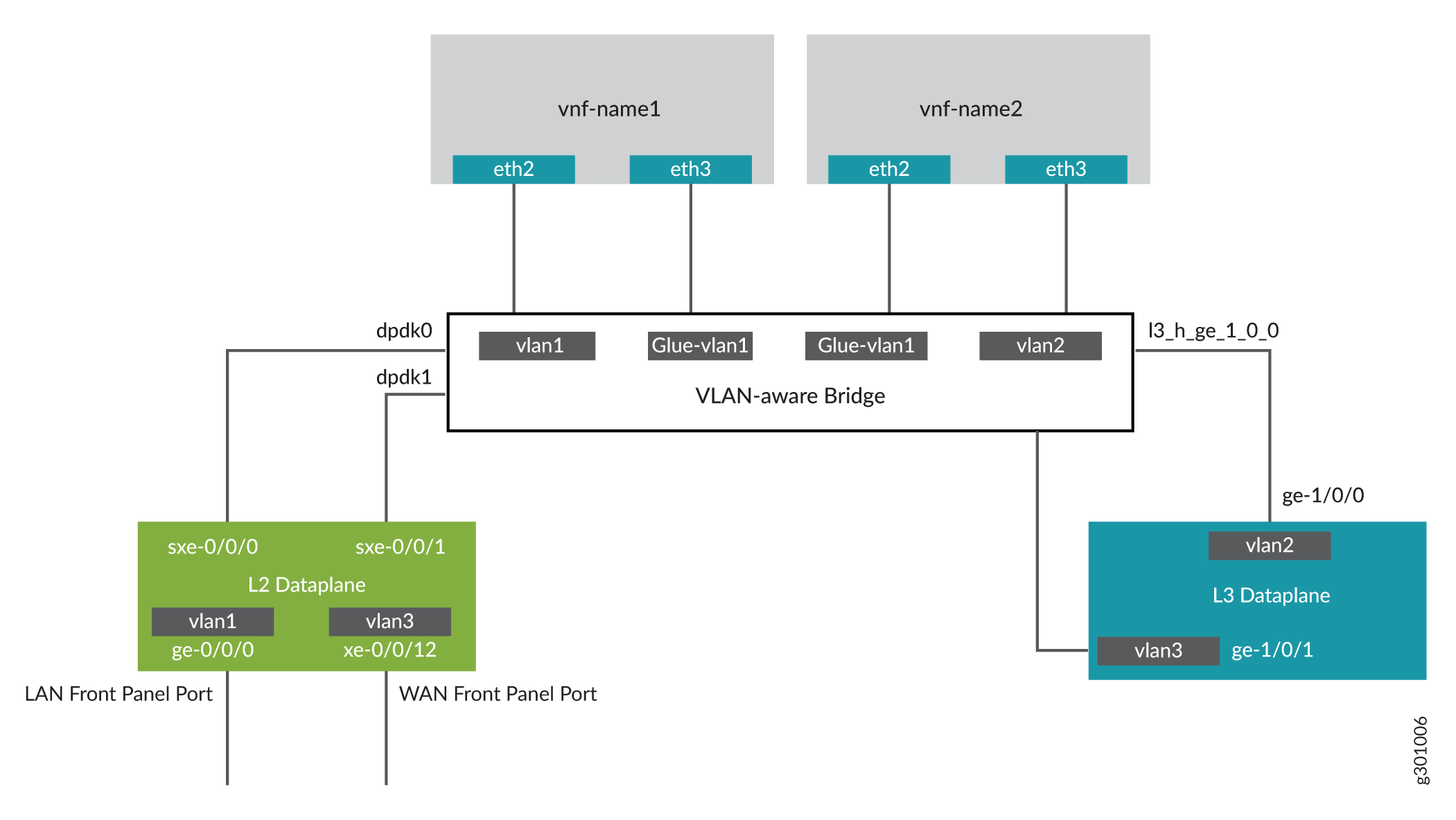
This example is configured using the Junos Control Plane (JCP). The key configuration elements include:
Front panel ports
Internal-facing ports
VNF interfaces, which use the naming format eth# (where # ranges from 0 through 9)
VLANs to provide bridging between the static interfaces (sxe) and VNF interfaces
Configuration
Configuring the JCP Interfaces
Step-by-Step Procedure
To configure the interfaces:
Connect to the JCP.
user@host:~ # cli
user@host>
user@host> configure
[edit]
user@host#
Map the Layer 3 interface to the Open vSwitch (OVS).
user@host# set vmhost virtualization-options interfaces ge-1/0/1
Configure a VLAN for the LAN-side interfaces.
user@host# set vlans vlan1 vlan-id 77
Configure the LAN-side front panel port and add it to the LAN-side VLAN.
The LAN-side port is typically an access port, but can be a trunk port if required.
user@host# set interfaces ge-0/0/0.0 family ethernet-switching vlan members vlan1
Configure the LAN-side internal-facing interface as a trunk port and add it to the LAN-side VLAN.
The internal-facing interfaces are typically trunk ports as they must support traffic from multiple front panel ports and VLANs.
user@host# set interfaces sxe-0/0/0.0 family ethernet-switching interface-mode trunk
user@host# set interfaces sxe-0/0/0.0 family ethernet-switching vlan members vlan1
Configure the WAN-side internal-facing interface as a trunk port and add it to the WAN-side VLAN.
user@host# set interfaces sxe-0/0/1.0 family ethernet-switching interface-mode trunk
user@host# set interfaces sxe-0/0/1.0 family ethernet-switching vlan members vlan3
Configure the WAN-side front panel port and add it to the WAN-side VLAN.
user@host# set interfaces xe-0/0/12.0 family ethernet-switching interface-mode access
user@host#  set interfaces xe-0/0/12.0 family ethernet-switching vlan members vlan3
Configure a VLAN for the WAN-side interface.
user@host# set vlans vlan3 vlan-id 1178
-
Configure VLAN tagging on the WAN-side external-facing interface and assign an IP address.
user@host# set interfaces ge-1/0/1 vlan-tagging
user@host# set interfaces ge-1/0/1.0 vlan-id 1178
user@host#  set interfaces ge-1/0/1.0 family inet address 192.0.2.1/24
Configure the WAN-side internal-facing interface as a VLAN-tagged interface and assign an IP address to it.
user@host# set interfaces ge-1/0/0 vlan-tagging
user@host# set interfaces ge-1/0/0.0 vlan-id 1177
user@host#  set interfaces ge-1/0/0.0 family inet address 203.0.113.2/24
Commit the configuration.
user@host# commit
Results
From configuration mode, check the results of your configuration by entering the following show commands:
[edit]
user@host# show interfaces ge-0/0/0
mtu 9192;
unit 0 {
family ethernet-switching {
vlan {
members [ vlan1 ];
}
}
}[edit]
user@host# show interfaces ge-1/0/0
vlan-tagging;
unit 0 {
vlan-id 1177;
family inet {
address 203.0.113.2/24;
}
}
[edit]
user@host# show interfaces ge-1/0/1
vlan-tagging;
unit 0 {
    vlan-id 1178;
    family inet {
          address 192.0.2.1/24;
    }
}
[edit]
user@host# show interfaces sxe-0/0/0
mtu 9192;
unit 0 {
    family ethernet-switching {
        interface-mode trunk;
        vlan {
            members [ default vlan1 ];
        }
    }
}
[edit]
user@host# show interfaces sxe-0/0/1
mtu 9192;
unit 0 {
family ethernet-switching {
interface-mode trunk;
vlan {
members [ vlan3 ];
}
}
}
[edit]
user@host# show interfaces xe-0/0/12
mtu 9192;
unit 0 {
family ethernet-switching {
vlan {
members [ vlan3 ];
}
}
}
[edit]
user@host# show vlans
default {
vlan-id 1;
}
vlan1 {
vlan-id 77;
}
Vlan3 {
vlan-id 1178;
}
Configuring the VNF Interfaces and Creating the Service Chain
Step-by-Step Procedure
Configure the VNF interfaces.
Configure the vmhost instance with the LAN, WAN, or the glue VLANs to be used for service chaining:
user@host# set vmhost vlans vlan1 vlan-id 77
user@host# set vmhost vlans vlan2 vlan-id 1177
user@host# set vmhost vlans glue-vlan1 vlan-id 123
Instantiate the VNF (vnf-name1) with one virtio interface mapped to the VLAN vlan1 and the other virtio interface mapped to the VLAN glue-vlan1.
user@host# set virtual-network-functions vnf-name1 interfaces eth2 mapping vlan members vlan1
user@host# set virtual-network-functions vnf-name1 interfaces eth3 mapping vlan members glue-vlan1
Instantiate the second VNF (vnf-name2) with one interface mapped to the VLAN vlan2 and the second interface mapped to the same glue-vlan1.
user@host# set virtual-network-functions vnf-name2 interfaces eth2 mapping vlan members glue-vlan1
user@host# set virtual-network-functions vnf-name2 interfaces eth3 mapping vlan members vlan2
Configure the IP addresses and static routes for each interface of the VNFs as shown in Figure 1.