Solution Architecture
The 3-Stage Fabric with Juniper Apstra is an EVPN/VXLAN-based validated design based upon the ERB network architecture. Using an ERB network architecture provides the design increased resilience by assigning specific functions to each device role and ensuring that each device role can be scaled independently of the others. Each network switch participating in the design must occupy one of three roles:
- Server Leaf Switches
The leaf switch focuses on learning and advertising the local MAC Addresses to other remote switches through the BGP EVPN control plane. This means leaf switches can discover all the “remote” hosts without flooding the overlay with ARP/ND requests.
- Border Leaf Switches
Although a border leaf can function as a server leaf switch, it can also act as a gateway to external networks and hence require DCI features. DCI features include connecting to network overlays such as VMware NSX-T, MACSEC, deep buffers, and so on.
- Spine Switches
The spine switch only performs IP forwarding and relaying of routes to all server and border leaf switches. As a result, spine switches in ERB network architectures are referred to as lean spines.
The use of an ERB network architecture and the associated switch roles not only simplifies the data center design but also provides flexibility at the leaf layer so that new leaf switches can be introduced as traffic throughput increases. Another aspect of this design is the use of non-modular switches, such as the 1U QFX5130-32CD, which can perform high throughput functions at the leaf layer.
To summarize, the ERB network architecture, which underlies the 3-stage fabric with Juniper Apstra, can be thought of as a distributed chassis. In an ERB network, leaf switches are roughly analogous to a “line card” in a traditional modular chassis, while the lean spine means the network fabric is more flexible and resilient than a single modular chassis switch. This creates a network more capable and flexible than a traditional modular chassis-based switch, without requiring the purchase or maintenance of a modular chassis-based switch for most enterprise data center scenarios.
For those data centers looking for scale that can only be achieved with chassis-based switches, the Juniper Validation process does take this into account, validating modular chassis switch combinations in ERB network roles. The result is validated network fabrics that can scale from the needs of individual racks up to serving entire data centers and beyond.
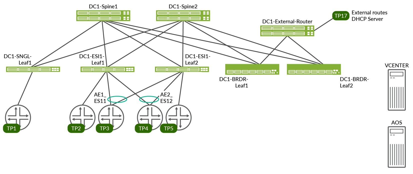
Figure 1 depicts the hardware in various roles such as spine, leaf, and border leaf. This JVD will walk through the high-level steps required to configure a 3-stage Data center, with QFX5220-32CD switches in the spine role, QFX5130-32CD switches in the border leaf role, and QFX5120-48Y switches in the server leaf role. These switches in these roles are considered the baseline design of this JVD, though other switches are qualified for these roles, as documented below.
Below is the reference architecture of 3-Stage Fabric with Juniper Apstra.
VRF Characteristics
RED VRF
- VLANs 400–649 with IRB v4/v6
- on DC1-SNGL-LEAF1 single access port
- on DC1-ESI-LEAF1 single access port, AE1 and AE2
- on DC1-ESI1-LEAF2 single access port, AE1 and AE2
- on DC1-BRDR-LEAF1 to distribute routes to external-router
- on DC1-BRDR-LEAF2 to distribute routes to external-router
- VLANs 400–649 on each test port with 10 unique MAC/IP per VLAN
- DHCP client on TP3
- External DHCP server on TP17
Blue VRF
- VLANs 3500–3749 with IRB v4/v6
- on DC1-SNGL-LEAF1 single access port
- on DC1-ESI-LEAF1 single access port, AE1 and AE2
- on DC1-ESI1-LEAF2 single access port, AE1 and AE2
- on DC1-BRDR-LEAF1 to distribute routes to external-router
- on DC1-BRDR-LEAF2 to distribute routes to external-router
- VLANs 3500–3749 on each test port with 10 unique MAC/IP per VLAN
- DHCP client on TP3, TP4, TP5
- External DHCP server on TP2
Juniper Hardware and Software Components
For this solution, the Juniper products and software versions are as below.
The design documented in this JVD is considered the baseline representation for the validated solution. As part of a complete solutions suite, we routinely swap hardware devices with other models during iterative use case testing. Each switch platform validated in this document goes through the same rigorous role-based testing using specified versions of Junos OS and Apstra management software.
Juniper Hardware Components
The following switches are tested and validated to work with the 3-Stage Fabric with Juniper Apstra JVD in the following roles:
| Supported Devices and Positioning | |||
|---|---|---|---|
| Solution | Server Leaf Switches | Border Leaf Switches | Spine |
| 3-stage EVPN/VXLAN (ERB) | QFX5120-48Y-8C* | QFX5130-32CD* | QFX5220-32CD* |
| QFX5110-48S | QFX5700 | QFX5120-32C | |
| EX4400-24MP# | ACX7100-48L | QFX5210-64CD | |
| ACX7100-32C | QFX5200-32C | ||
| PTX10001-36MR | |||
| QFX10002-36Q | |||
* marked are baseline devices
There is a scale limitation on EX4400 switches that affects the whole fabric. Refer to the Multi-dimensional Scale Numbers Tested Table 1 for scale numbers with EX4400. The version used for validation for EX4400 was 22.4R3.25 as this version supports MAC-VRF feature. Please contact Juniper account representative for more information about EX4400 setup and scale.
For more information on validated devices refer to Devices Under Test(Validated Devices) Table 1.
For the purposes of this JVD document, the following switches are used for the configuration walkthrough:
| Juniper Hardware for 3-Stage Design | |||
|---|---|---|---|
| Juniper Products | Role | Hostname | Software or Image Version |
| QFX5220-32CD | Spine | dc1-spine1 & dc1-spine2 | Junos OS Evolved Release 23.4R2-S3 |
| QFX5120-48Y | Server Leaf |
dc1-single-leaf1 dc1-esi-001-leaf1 dc1-esi-001-leaf2 |
Junos OS Release 23.4R2-S3 |
| QFX5130-32CD | Border Leaf |
dc1-border-leaf1 dc1-border-leaf2 |
Junos OS Evolved Release 23.4R2-S3 |
All devices listed in Supported Devices and Positioning Table 1 are validated against Junos OS Release 23.4R2-S3 release. The validated Junos OS release for PTX10001-36MR is Junos OS Evolved Release 23.4R2-S3, for ACX7100-32C and ACX7100-48L is Junos OS Evolved Release 23.4R2-S3.
| Juniper Software | |
|---|---|
| Juniper Products | Software or Image Version |
| Juniper Apstra | 4.2.1-207 |
Validated Functionality
The 3-Stage Fabric with Juniper Apstra was validated using the following parameters in its configuration:
- This JVD consists of a 3-stage CLOS with an ERB network architecture using EVPN-VXLAN.
- Servers will be connected and tested both in single-homed and multi-homed configurations.
- In the case of multihomed ESI servers, LACP is enabled between the servers and the leaf switches.
- Configure ESI on aggregated ethernet interfaces for multi-homed devices.
- ECMP is configured across the fabric to minimize traffic loss.
- Both the overlay and underlay of the fabric are built using eBGP.
- Learn and advertise EVPN Type 2 and Type 5 routes.
- BFD is enabled for both underlay eBGP and overlay eBGP.
- Asymmetric IRB is enabled with anycast IP address on L3-enabled leaf switches for inter-VLAN routing. For more information on the IRB model for inter-subnet forwarding in EVPN, refer to the EVPN VXLAN Guide.
- Both IPv4 and IPv6 are enabled; however, IPv6 is only used for loopback.
- Inter-VRF connectivity is configured using external router to allow route leaking between VRFs, however, to achieve this configuration Apstra Connectivity templates were used to connect to the external router.
Additional Functionality
The below features are not considered part of, nor are described in, this JVD; however, they are validated:
- DCI between data centers.
- Interoperability with NSX-T Edge Gateway.
- Host connectivity between fabric-connected hosts created by Apstra towards NSX-managed hosts.