Test Objectives
JVD is a cross-functional collaboration between Juniper solution architects and test teams to develop coherent multidimensional solutions for domain-specific use cases. The JVD team comprises technical leaders in the industry with a wealth of experience supporting complex use cases. The scenarios selected for validation are based on industry standards to solve the critical business needs with practical network and solution designs.
The key goals of the JVD include:
- Validate overall solution integrity and resilience
- Support configuration and design guidance
- Deliver practical, validated, and deployable solutions
A reference architecture is selected after consultation with Juniper Networks global theaters and a deep analysis of use cases. The design concepts that are deployed use best practices and leverage relevant technologies to deliver the solution scope. KPIs are identified as part of an extensive test plan that focuses on functionality, performance integrity, and service delivery.
Once the physical infrastructure required to support the validation is built, the design is sanity-checked and optimized. Our test teams conduct a series of rigorous validations to prove solution viability, capturing, and recording results. Throughout the validation process, our engineers engage with software developers to quickly address any issues found.
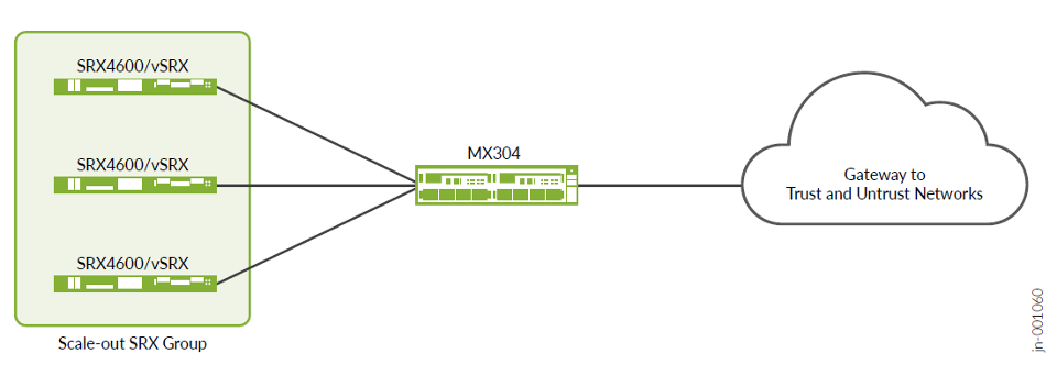
The test objective is to validate the scale-out architecture, showing the various topologies with single/dual MX Series Routers and multiple SRX Series Firewalls, and demonstrate its ability to respond to various use cases while being able to scale. The different possibilities offered by routing, and the two main load balancing methods, using different platform sizes for MX Series Router and/or SRX Series Firewalls, using high availability of the various components.
Additional goals demonstrate scale-out capability of the solution, which allows linear performance and logical scale (number of IPsec tunnels) growth in the process of new SRX/vSRX Series Firewalls in addition to the security services complex.
This JVD validates system behavior under the following administrative events, with a general expectation to have no or little effect on the traffic:
- Adding a new SRX Series Firewall to the service layer helps in redistribution of traffic to get an even distribution, minor percentage of traffic disturbance [depends on the number of SRX Series Firewalls next-hops] is seen on all other SRX Series Firewall due to change in next-hops and then the hash.
- Removing a SRX Series Firewalls from the service layer causes traffic redistribution only for those associated to this removed SRX Series Firewalls.
- Having a SRX Series Firewalls failover to its peer (MNHA case) and returns to a normal state causes no traffic disruption and preserves sessions and IPsec Security Associations.
- Having an MX Series Router failover (dual MX Series Router) causes no traffic disruption.
- Varying themes and failure scenarios cause no traffic disruption.
The following networking features are deployed and validated in this JVD:
- Dynamic routing using BGP
- Dynamic fault detection using BFD
- Load balancing of IKE/IPsec sessions across multiple SRX Series Firewalls in standalone or high availability
- Load balancing using ECMP CHASH, first appeared in Junos OS Release 13.3R3
- Load balancing using TLB on the MX Series Router (TLB, first appeared in Junos OS Release 16.1R6)
- MX Series Router redundancy using BGP dynamic routing between two MX Series Router with TLB
- SRX Series Firewalls redundancy using MNHA as Active/Active with IKE/IPsec SA synchronization
- Dual stack solution with IPv4 and IPv6
- IKE/IPsec tunnel negotiation using AES-GCM encryption protocols as responder mode (waiting for IPsec peers, SRX Series Firewalls IPsec configured with auto-vpn mode)
- DPD (Dead Peer Detection) helps in detecting unreachable IKE peers. It helps to maintain a link active while no traffic flows inside and detect end to end VPN reachability issues.
Test Non-Goals
This JVD does not mention automation. However, automation is used to build and test the solution with various use cases and tests.
Maximum scale and performance of the individual network elements constitute the solution. There is no preferred specification for the hypervisor hosting the vSRX firewall, nor any specific vSRX sizes (in vCPU/vRAM/vNIC quantity). Simple vSRX firewalls are enough for testing the features.
vSRX firewall runs on many hypervisors including ESXi, KVM, and Microsoft for on-prem. Though vSRX firewall can also be deployed in public clouds like AWS, Azure and GCP, the purpose of the architecture is not to run with vSRX firewall in those external clouds where it might be questionable to consider the networking plumbing to get them connected.
Following features and functions are not included in this JVD:
- Automated onboarding of the vSRX firewall
- Security Director
- Application and Advanced Security features such as AppID, IDP, URL filtering, and other Layer 7
- IKE/IPsec tunnel negotiation using other protocols than AES-GCM or other initiator mode (to other peers)
- IKE using PKI (Public Key Infrastructure) is not used; however, it works the same
Tested Failure Events
SRX Series Firewalls failure events are:
- MX Series Router to SRX Series Firewall link failures
- SRX Series Firewall reboot
- SRX Series Firewall power off
- Complete MNHA pair power off
- IKE/IPsec failures
MX Series Router failure events are:
- Reboot MX Series Router
- Restart routing process
- Restart TLB process in MX Series Router (traffic-dird, sdk-process and netmon deamon)
- GRES (Graceful Restart of routing daemon)
- ECMP/TLB next-hop addition or deletion (adding or deleting a new scale-out SRX MNHA pair)
- SRD based CLI switchover between MX Series Router (ECMP)
Traffic recovery is validated post all failure scenarios.
- UDP traffic generated using IXnetwork for all the failure related test cases is used to measure the failover convergence time.
Tested Traffic Profiles
Tested traffic profiles shared above are composed of multiple simultaneous flows showing the same for either a standalone SRX Series Firewalls or a SRX MNHA pair in Active/Active mode.
| Tunnel Count/ MNHA-Pair | Packet Size | Traffic Type | Throughput | Platform |
|---|---|---|---|---|
| 1000 | SECGW-IMIX | UDP | 40Gbps | SRX4600 |
| 1000 | SECGW-IMIX | UDP | 40Gbps | vSRX, CPU/vSRX :90% |
These performances are not at their maximum capability for each platform. However, a steady performance representative to test among multiple SRX4600/vSRX in similar conditions.
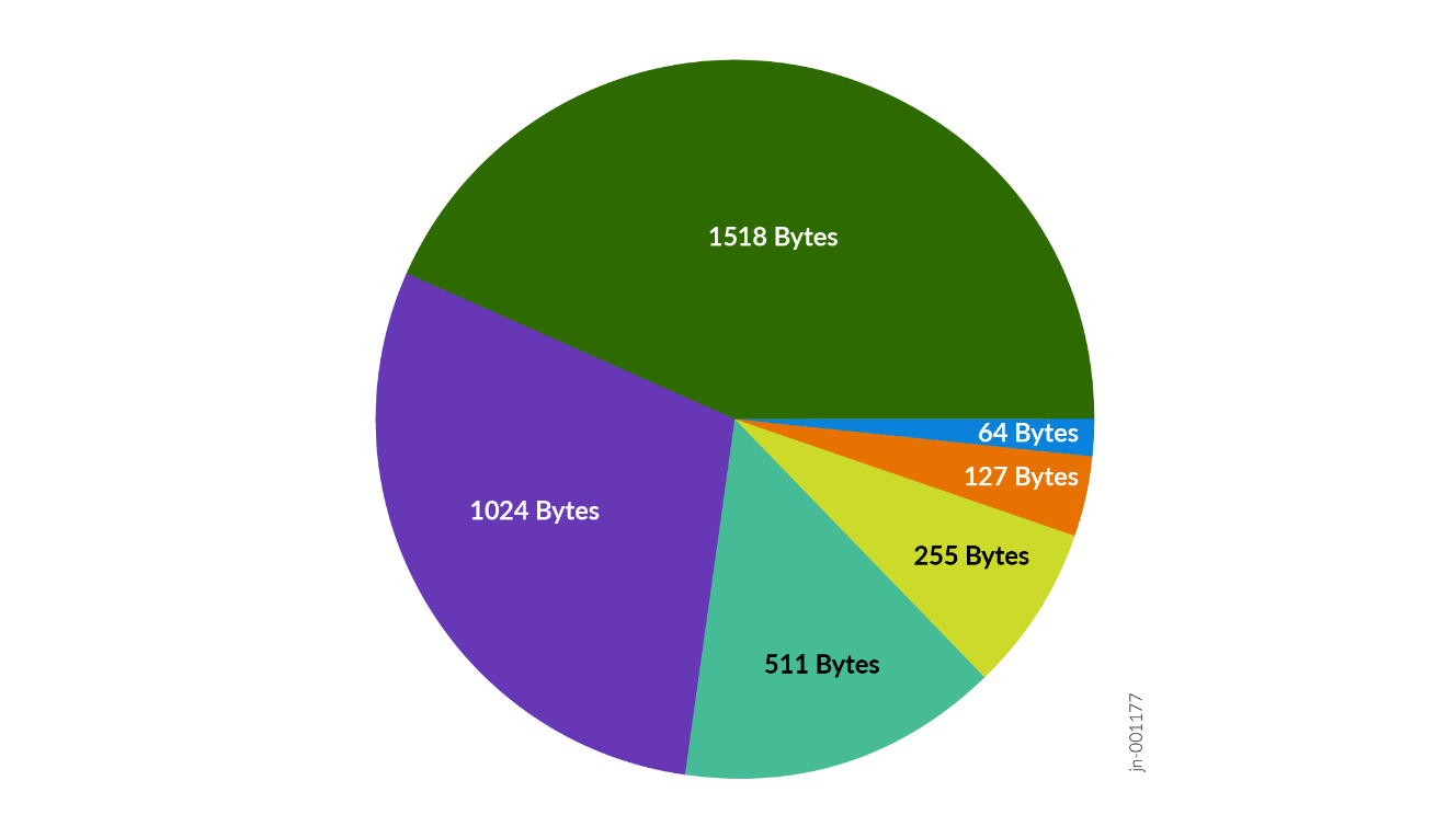
Packet size is using the SECGW-IMIX Internet with average packet size of ~700bytes. “Packet Size: Weight” distribution is as follows:
- 64:8
- 127:36
- 255:11
- 511:4
- 1024:2
- 1518:39
The lab used end to end 9000 for MTU to prevent fragmentation.
Test Bed Configuration
Contact Juniper or your Juniper account representative to obtain the full archive of test bed configuration used for this JVD.
Traffic Path in IPsec Scale-Out Solution
The scale-out solution is based on BGP as dynamic routing protocol. It enables all the MX Series Router and SRX Series Firewalls to learn from their surrounding networks, however, most importantly to exchange path information for the network traffic that needs to be sent from the MX Series Router across each SRX Series Firewalls to the next MX Series Router. This protocol enables exchange of network paths for the internal/user subnets and the default/specific external network. When each SRX Series Firewalls announces what it has learned from the other side, each with the same “network cost”, the load balancing mechanism can then use those routes for sending traffic simultaneously across each SRX Series Firewalls. In case of IPsec traffic, one side needs to announce the IP addresses used for establishing the tunnel (the IKE destination at minimum), and the other side announces the inner traffic transported over IPsec (the IP addresses allocated to each mobile device).
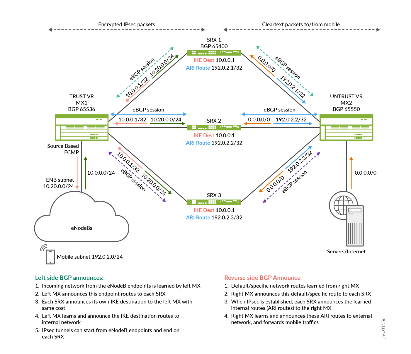
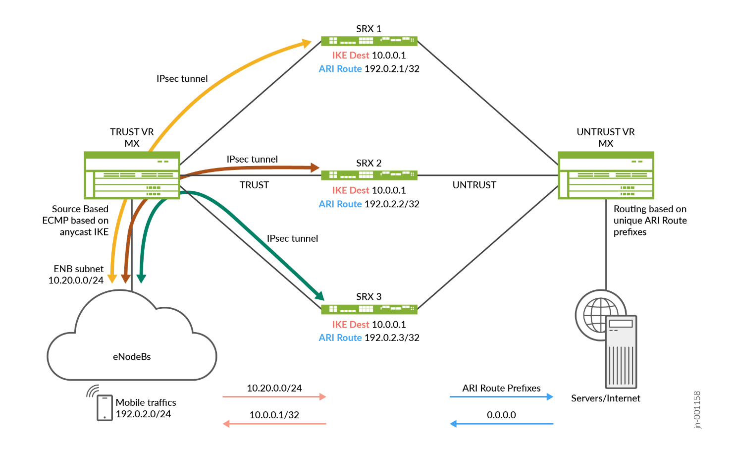
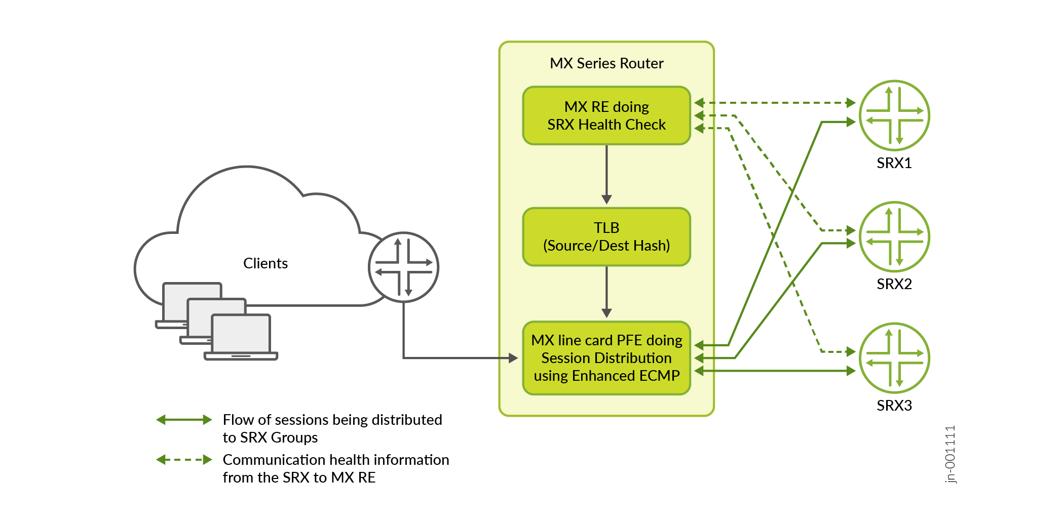
The following diagram shows how traffic flows might be distributed from an MX Series Router to multiple SRX Series Firewalls using ECMP load balancing method for the IKE/IPsec traffic started from the ENB in a mobile network. The SRX Series Firewalls are a symmetric sandwich between the two MX Series Routers in the diagram, whether those MX Series routers are a single physical node configured with two routing instances (more typical) or two physical MX Series Router nodes on each side. The routing principle remains the same as if two routing nodes are used, maintaining the traffic flow distribution that is consistent in both directions. However, one side of the SRX Series Firewalls has encrypted traffic and the other side has clear text traffic to/from the mobile endpoint.
The MX Series Router on the left uses TRUST-VR routing instance to forward traffic to each SRX Series Firewalls. On the left side, only IPsec traffic is seen and IP addresses to announce are the ones used by the mobile gateways (eNodeBs) and the same IKE gateway IP address is used by each SRX Series Firewalls. The routes on this side are announced through BGP to the next hop, making its path available on each MX Series Router through each SRX Series Firewalls (with same cost for load balancing).
The MX Series Router on the right has used UNTRUST-VR to receive traffic from each SRX Series Firewalls and forward it to the next-hop toward the target resources. When an IPsec tunnel is established on the left side (eNodeB to SRX Series Firewalls), it negotiates (as part of the IPsec security association) an inner IP address(es) assigned to the mobile device, these are IP-addresses that are announced through BGP to the UNTRUST VR on the right side, making the return path unique toward the specific SRX Series Firewalls hosting IPsec security association for the given eNodeB (the diagram shows a unique IP address each time with a /32 prefix for IPv4, and an IPv6 shows a /128 prefix).
Routes are announced through BGP, each MX Series Router with their own BGP Autonomous System (AS) and peer with the SRX Series Firewalls on their two sides (TRUST and UNTRUST zones in a single routing instance). The MX Series Router might peer with any other routers bringing connectivity to the clients and servers.
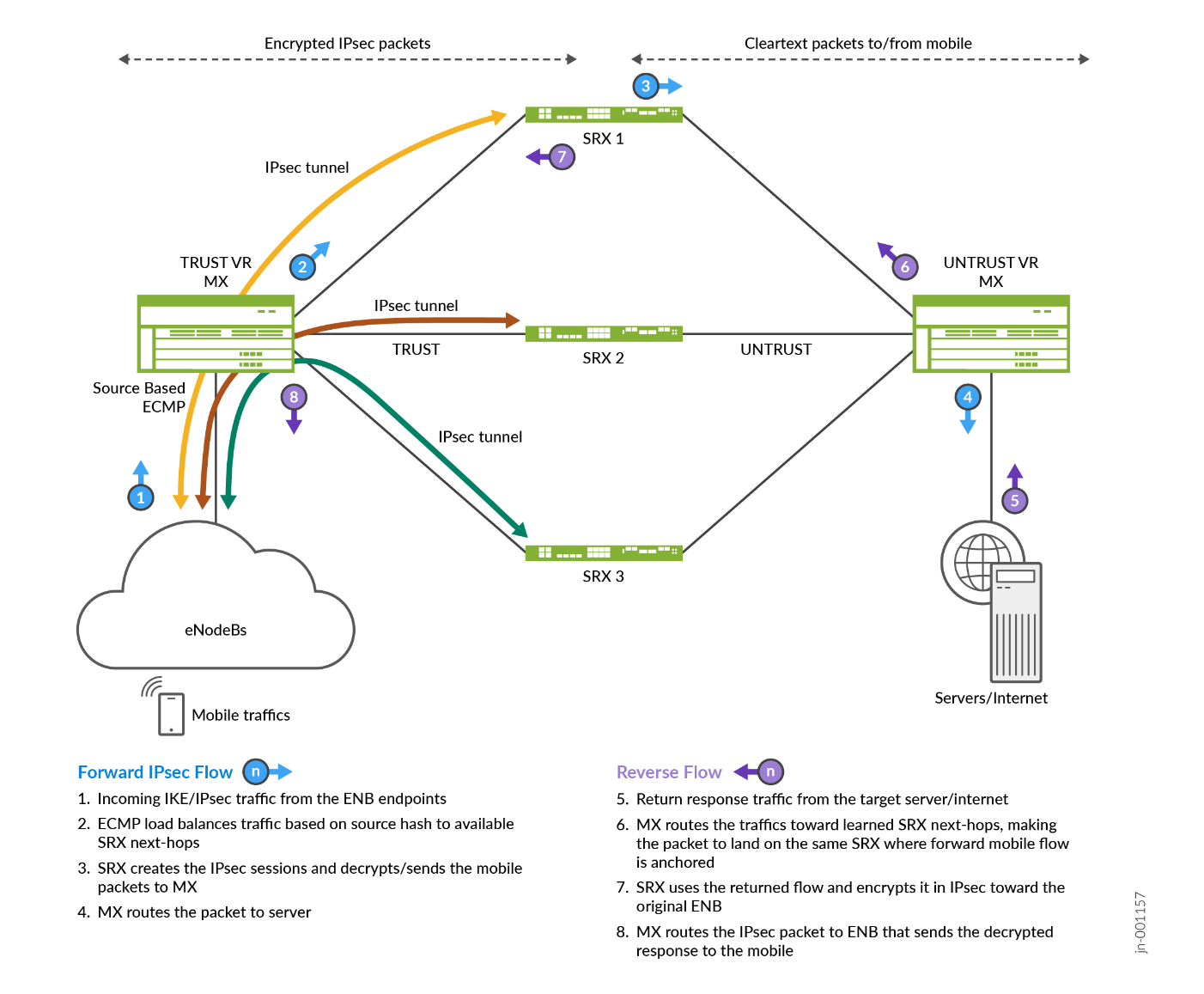
Figure 3 shows how the mobile traffic comes through the mobile gateway (eNodeB). This starts an IPsec negotiation with one of the SRX Series Firewalls (destination being selected by the load balancing mechanism), then transported over IPsec to the SRX Series Firewalls. This SRX Series Firewalls then decrypts the packet and sends the content to the next hop. The return path across the right SRX Series Firewalls is known to the ARI route (Auto Route Injection) announced by the SRX Series Firewalls to the MX Series Routers on the right side.
Introduction to SRX Series Firewalls Multinode High Availability (MNHA)
For more information, see an extract from the public documentation on MNHA https://www.juniper.net/documentation/us/en/software/junos/high-availability/topics/topic-map/mnha-introduction.html .
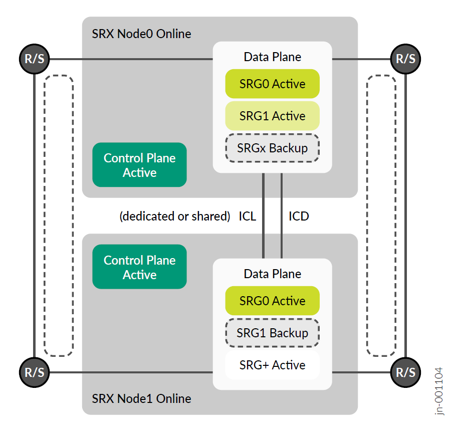
Juniper Networks SRX Series Firewalls support Multi Node High Availability (MNHA), starting from Junos OS Release20.4 and later, to address high availability requirements for modern networks. In this solution, both the control plane and the data plane of the participating SRX Series Firewalls (nodes) are active at the same time. Thus, the solution provides inter-chassis resiliency.
The participating devices are either co-located or geographically separated to different rooms or buildings. Having nodes with HA across geographical locations ensures resilient service. If a disaster affects one physical location, MNHA can fail over to a node in another physical location, thereby ensuring continuity.
In MNHA, both SRX Series Firewalls have an active control plane and communicate their status over an Inter Chassis Link (ICL) that can be direct or routed across the network. This allows the nodes to be geo-dispersed while synchronizing the sessions and IKE security associations. Also, they do not share a common configuration, and this enables different IP addresses settings on both SRX Series Firewalls. There is a commit sync mechanism that are used for the elements of configuration to be same on both platforms.
The SRX Series Firewalls uses one or more services redundancy groups (SRGs) for the data plane that can be either active or backup (for SRG1 and above). An exception is the SRG group 0 (zero) that is always active on both. This group is used natively by scale-out solution to load balance the traffic across both SRX Series Firewalls at the same time. However, some interest exists for the other modes where it can be Active/Backup for SRG1 and Backup/Active for SRG2. SRG0 is always active, however one can also add routing information (like BGP as-path-prepend) under certain conditions. SRG1/+ offers more health checking of its surrounding environment that can be leveraged to make an SRGn group active/backup/ineligible.
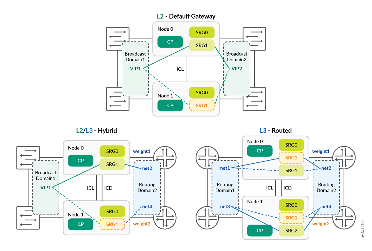
MNHA can select a network mode between the following three possibilities:
- Default Gateway or L2 mode: It uses the same network segment at L2 on the different sides of the SRX Series Firewalls (for example, TRUST and UNTRUST) and both SRX Series Firewalls share a common IP / MAC address on each network segment. It does not mean the SRX Series Firewalls is in switching mode, it does route between its interfaces, however, shares the same broadcast domain on one side with the other SRX Series Firewalls, and same on the other side as well.
- Hybrid mode or mix of L2 and L3: It uses an L2 and IP address on one side of the SRX Series Firewalls (for example, TRUST) and routing on the other side (for example, UNTRUST) then having different IP subnets on the second side.
Routing mode or L3: This architecture is used for this JVD where each side of the SRX Series Firewalls uses a different IP address, even between the SRX Series Firewalls (no common IP subnet) and all communication with rest of the network happens through routing. This mode is perfect for scale-out communication using BGP with the MX Series Router.
Whether using SRG0 Active/Active, or SRG1 Active/Backup (single one active at a time), or a combination of SRG1 Active/Backup and SRG2 Backup/Active, this simply uses one or two SRX Series Firewalls in a cluster at the same time.
ECMP/Consistent Hashing (CHASH) Load Balancing Overview
This feature relates to topology 1 (single MX Series Router, scale-out SRX Series Firewalls).
ECMP/Consistent Hashing (CHASH) in MX Series Router
ECMP is a network routing strategy that transmits traffic of the same session, or flow — that is, traffic with the same source and destination across multiple paths of equal cost. It is a mechanism that allows to load balance traffic and increase bandwidth (by fully utilizing) otherwise unused bandwidth on links to the same destination.
When forwarding a packet, the routing technology must decide which next-hop path to use. The device considers the packet header fields that identify a flow. When ECMP is used, next-hop paths of equal cost are identified based on routing metric calculations and hash algorithms. That is, routes of equal cost have the same preference and metric values, and the same cost to the network. The ECMP process identifies a set of routers, each of which is a legitimate equal cost next-hop towards the destination. The routes that are identified are referred to as an ECMP set. An ECMP set is formed when the routing table contains multiple next-hop addresses for the same destination with equal cost (routes of equal cost have same preference and metric values). If there is an ECMP set for the active route, Junos OS uses a hash algorithm to choose one of the next-hop addresses in the ECMP set to install in the forwarding table. You can configure Junos OS so that multiple next-hop entries in an ECMP set are installed in the forwarding table. On Juniper Networks devices, per-packet load balancing is performed to spread traffic across multiple paths between routing devices.
The following example is of learned routes and forwarding table for the same destination (assuming traffic target is exact IP address 10.0.0.1/32 and SRX Series Firewalls BGP peers are 10.1.1.0, 10.1.1.8 and 10.1.1.16):
jcluser@mx-01> show route 10.0.0.1/32
trust-vr.inet.0: 30 destinations, 33 routes (30 active, 0 holddown, 0 hidden)
+ = Active Route, - = Last Active, * = Both
10.0.0.1/32        *[BGP/170] 4d 04:52:53, MED 10, localpref 100
                      AS path: 64500 64500 I, validation-state: unverified
                       to 10.1.1.0 via ae1.0      ## learning routes from BGP peer SRX1
                    >  to 10.1.1.8 via ae2.0      ## learning routes from BGP peer SRX2
                       to 10.1.1.16 via ae3.0     ## learning routes from BGP peer SRX3
jcluser@mx-0> show route forwarding-table destination 10.0.2.0/24 table trust-vr
Routing table: trust-vr.inet
Internet:
Destination        Type RtRef Next hop           Type Index    NhRef Netif
10.0.0.1/32       user     0                    ulst  1048580     2
                              10.1.1.0           ucst      801     4 ae1.0       ## to SRX1
                              10.1.1.8           ucst      798     5 ae2.0       ## to SRX2
                              10.1.1.16          ucst      799     5 ae3.0       ## to SRX3
With scale-out architecture where stateful security devices are connected, maintaining symmetricity of the flows in the security devices is the primary objective. The symmetricity means traffic from a subscriber (user) and to the same subscriber must always go through the same SRX Series Firewalls (which maintains the subscriber state). To reach the same SRX Series Firewalls, the traffic must be hashed onto the same link towards that SRX Series Firewalls in both directions.
A subscriber (eNodeB) is identified by the source IP address in the upstream direction (client to server) and by the destination IP address in the downstream direction (server to client). The MX Series Routers do symmetric hashing i.e. for a given (sip, dip) tuple, same hash is calculated irrespective of the direction of the flow i.e. even if sip and dip are swapped. However, the requirement is that all flows from a subscriber reach the same SRX Series Firewalls, so you need to hash only the source IP address (and not destination IP address) in one direction and vice versa in the reverse direction.
However, in the present security gateway use case, traffic is not the same on both sides of the Firewall. On the left side, there is IPsec, coming from eNodeBs and terminating on the SRX Series Firewalls, and the inner traffic from the mobile itself from the SRX Series Firewalls on the right side and going to Internet. However, the symmetry of the traffic still needs to be true. In that case, the SRX Series Firewalls receiving initial IKE/IPsec request establishes a tunnel with the source of that tunnel (eNodeB), and in the IPsec negotiation (IKE phase 2), some source/destination IP addresses are negotiated (i.e. the traffic selector or encryption domain depending on the language used). In the mobile world, this source IP address negotiated in this traffic selector is the one that is then used and announced through BGP to the next MX Series Router in the chain (this is the ARI route, aka Auto Route Injection). This makes the return traffic to that mobile reach the correct SRX Series Firewalls and then routing that traffic back into the proper IPsec tunnel to its destination eNodeB.
By default, when a failure occurs in one or more paths, the hashing algorithm recalculates the next hop for all paths, typically resulting in redistribution of all flows. Consistent load balancing enables you to override this behavior so that only flows for inactive links are redirected. All existing active flows are maintained without disruption. In such an environment, the redistribution of all flows when a link fails potentially results in significant traffic loss or a loss of service to SRX Series Firewalls whose links remain active. However, consistent load balancing maintains all active links and remaps only those flows affected by one or more link failures. This feature ensures that flows connected to links that remain active continue to remain uninterrupted.
This feature applies to topologies where members of an ECMP group are external BGP neighbors in a single-hop BGP session. Consistent load balancing does not apply when you add a new ECMP path or modify an existing path in any way. The new SRX Series Firewalls add design is implemented recently where you can add SRX Series Firewalls gracefully with an intent of equal redistribution from each active SRX Series Firewalls, hence causing minimal impact to the existing ECMP flows. For example, if there are four active SRX Series Firewalls carrying 25% of total flows on each link and a 5th SRX Series Firewalls (previously unseen) is added, 5% of flows from each existing SRX Series Firewalls moves to the new SRX Series Firewalls. Hence making 20% of flow redistribution from existing four SRX Series Firewalls to the new one.
In case of traffic redistribution (loss of a single SRX Series Firewalls or addition of a new SRX Series Firewalls), the IPsec peer renegotiate to that “new” peer IKE gateway as the Security Association does not exist yet.
In case of SRX MNHA pair, any failover (if losing its SRX Series Firewalls on other node) from one to another in the same pair reuses the existing synchronized IPsec Security Association and no renegotiation happens.
The following information shares details for each step of route exchange between MX Series Router and SRX Series Firewalls, traffic flows, for each use case.
ECMP/CHASH Usage in Topology 1 (Single MX Series Router, Scale-Out SRXs) for Security Gateway
Security gateways use cases usually accept IPsec connections from remote entities in a mobile network, typically eNodeB (4G antennas) and eNodeG (5G antennas). Those connections are then coming from the left slide on the following diagram and their respective internal traffic transported over IPsec it then decapsulated and sent to the right side, typically to Internet across Gi interface in a mobile network.
- All the scale-out SRX Series Firewalls connected to MX Series Router are configured with eBGP connections.
- All the scale-out SRX Series Firewalls need to be configured with Auto-vpn configuration and with same anycast IP address hosted on loopback interface as an IKE endpoint IP address. They use the IPsec Responder Only mode.
- The IPsec tunnels getting initiated behind MX Series Router from IPsec initiator uses same SRX Series Firewalls IKE endpoint IP address with unique traffic-selector. This traffic-selector is used by SRX Series Firewalls to install unique ARI routes to attract the data return traffic from the server to the correct IPsec tunnel.
- A load-balancing policy with source-hash for anycast IP address route is configured in the forwarding-table on MX Series routers.
- Anycast IP address route is received by MX Series Router on TRUST side and advertised using eBGP to MX Series Router on the TRUST side. The MX Series Router imports this route on the TRUST instance using load-balancing CHASH policy.
- The MX Series Router on the TRUST side has an ECMP route for anycast IP address.
- IKE traffic initiated from IPsec initiator router reaches the MX Series Router on TRUST instance and hits ECMP anycast IP address route and takes any one ECMP next hop to SRX Series Firewalls based on the calculated source IP address-based hash value.
- SRX Series Firewalls anchors the IKE session and installs the ARI route.
- SRX Series Firewalls advertises the ARI route towards the UNTRUST direction of MX Series Router.
- Clear-text packets initiated from clients behind IPsec router goes through the IPsec tunnel and reach the anchored IPsec tunnel on the SRX Series Firewalls. Clear-text packets coming out of the tunnel are routed toward the UNTRUST direction to reach the server.
- Clear-text packets reply to traffic from server toward clients reaches the MX Series Router on the UNTRUST direction and then gets routed through unique ARI route to the SRX Series Firewalls where tunnel is anchored.
- SRX Series Firewalls encrypt the traffic and send the traffic over the tunnel to the IPsec initiator and then to the client.
When any SRX Series Firewalls goes down, CHASH on the MX Series Router ensures IPsec sessions on the other SRX Series Firewalls are not disturbed and only IPsec sessions on the down SRX Series Firewalls are redistributed.
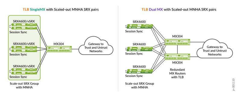
Traffic Load Balancer Overview
This feature relates to topology 2 (single MX Series Router, scale-out SRX MNHA pairs) and topology 3 (dual MX Series Routers and scale-out SRX MNHA pairs).
Traffic Load Balancer in MX Series Router
Traffic Load Balancer (TLB) functionality provides stateless translated or non-translated traffic load balancer, as an inline PFE service in the MX Series Routers. Load balancing in this context is a method where incoming transit traffic is distributed across configured servers that are in service. This is a stateless load balancer, as there is no state created for any connection, and so there are no scaling limitations. However, throughput can be close to line rate. TLB has two modes of load balancing i.e., translated (L3) and non-translated Direct Server Return (L3).
For the scale-out solution, the TLB mode non-translated Direct Server Return (L3) is used. As part of TLB configuration, there is a list of available SRX Series Firewalls addresses and the MX Series Router PFE programs selector table based on this SRX Series Firewalls. TLB does a health check (ICMP usually however it can do HTTP, Custom, and TCP checks) for each of the SRX Series Firewalls individually. TLB health check is done using MX Series Router routing engine. If the SRX Series Firewalls pass the health check, TLB installs a specific IP address route or wild card IP address (TLB config option) route in the routing table with next-hop as composite next-hop. Composite next-hop in the PFE is programmed with all the available SRX Series Firewalls in the selector table. Filter based forwarding is used to push the "Client to Server" traffic to the TLB where it hits the TLB installed specific IP address route or wild card IP address route to get the traffic sprayed across the available SRX Series Firewalls with source or destination hash. "Server to Client" is directly routed back to client instead of going through the TLB.
TLB has been used in the Junos OS and MX Series Routers family for a few years now (as early as Junos OS Release 16.1R6) and you are using it successfully on large server farms with around 20,000 servers.
TLB uses the control part and the health check on MS-MPC or MX-SPC3 service cards on MX240/480/960 and MX2000 chassis before data plane or PFE is already on the line cards. It is not running on the RE as it is implemented on MX304/MX10000 chassis.
For more information, see, https://www.juniper.net/documentation/us/en/software/junos/interfaces-next-gen-services/interfaces-adaptive-services/topics/concept/tdf-tlb-overview.html.
How TLB is Used in the MX Series Router for the Scale-Out SRX Series Firewalls Solution with Security Gateway
In this scenario, the source of IPsec traffic is mobile gateway (enodeB or gnodeB for a mobile SP) that resides on the left side of Figure 10 . When this site connects using IPsec to the SRX Series Firewalls, it is redirected by load balancing to one of the SRX Series Firewalls as Load Balancing handles it. It is represented the other way around for an enterprise however, the principle remains the same, only interface IP address, routing-instance, and zone naming might change. A unique anycast IP address is used for all IKE/IPsec connections, hosted on each SRX Series Firewalls as anycast address.
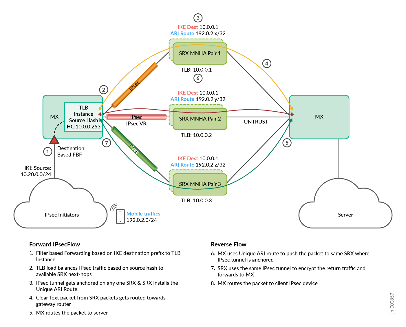
In Figure 10, MX Series Router is a single router configured with two IFL’s for IPsec VR and Internet. MX TLB does a health check to all the scaled-out SRX Series Firewalls and builds the next-hops for LB.
- All SRX Series Firewalls are configured with BGP to establish an eBGP peering sessions with MX Series Router nodes.
- All the scale-out SRX Series Firewalls need to be configured with auto-vpn config and with same anycast IP address as IKE endpoint IP address. All SRX Series Firewalls are in IPsec responder only mode.
- IPsec clients getting initiated behind MX Series Router uses same SRX Series IKE
endpoint IP address with unique traffic-selectors. SRX Series Firewalls uses
this traffic-selector to install unique ARI routes (Auto Route Injection) to
attract the data return traffic to the right IPsec tunnel from the server.Note:
The ARI routes need to be unique.
- MX Series Router is configured with TLB on the IPsec VR routing instance to do the load balancing of IKE traffic coming from MX Series Router towards scaled out SRX Series Firewalls.
- All the scale-out SRX Series Firewalls connected to MX Series Router are configured with unique IP address which is used by MX Series Router TLB to do the health check and build up the selector table in the PFE. PFE uses this selector table to load balance the packet across the available next hops. This health check is reachable through BGP connection. Anycast IP address used for IKE endpoint is reachable through this Unique IP address on each SRX Series Firewalls.
- Filter based forwarding based on source IP address match is used in MX Series Router to push the IPsec specific traffic to the TLB IPsec forwarding instance.
- TLB Forwarding instance has a default route with next hop as a list of SRX Series Firewalls. TLB installs this default route when its health check passes at least one SRX Series Firewalls.
- TLB load balances source-based-hash across all the available SRX Series Firewalls next-hop devices.
- Load balanced IPsec tunnel sessions are anchored on any available SRX Series Firewalls and it installs the ARI route. Then packet is decrypted and is routed to reach the server through MX Series Router over Internet routing instance.
- For the return traffic coming from server to client on the MX Series Router UNTRUST routing instance, Unique ARI routes are used to route the traffic back to the same SRX Series Firewalls where the IPsec tunnel is anchored.
- SRX Series Firewalls uses same IPsec tunnel session to encrypt the packet and route the IPsec traffic towards MX Series Router on the IPsec VR direction.
- MX Series Router routes the IPsec traffic back to IPsec Initiators.
Configuration Example for ECMP CHASH
The following sample configurations are proposed to understand the elements making this solution work, including configurations for both MX Series Router and some SRX Series Firewalls. It contains a lot of repetitive statements. It shows Junos OS hierarchical view.
Source-hash for forward flow and destination-hash for reverse flow is common for all the ECMP based solutions or TLB based solutions. CHASH is used during any next-hop failure where it helps an existing session on an active next-hop to remain undisturbed, while sessions on down next-hop is redistributed over other active next-hop. This CHASH behavior is pre-built in the TLB solution. However, in ECMP based solution you must configure this CHASH configuration explicitly using BGP import policy.
The following MX Series Router configuration is an example for ECMP load balancing using source hash on the TRUST side (only to IKE gateway unicast address shared by each SRX Series Firewalls):
### MX sample routing configuration:
policy-options {
    prefix-list clients_v4 {
        10.20.0.0/24;           ### source IPsec ENB clients 10.20.0.0/24
    }
    prefix-list IPsecGW_v4 {
        10.0.0.1/32;                    ### target IPsec gateway on SRX(s) 10.0.0.1/32
    }
    policy-statement pfe_lb_hash {
        term source_hash {
            from {
                 prefix-list-filter IPsecGW_v4 exact; ### target IPsec SRX gateway
            }
            then {
                load-balance source-ip-only;       ### when match, then LB per src-ip
                accept;
            }
        }
        term ALL-ELSE {
            then {
                load-balance per-packet;                ### per packet for anything else
                accept;
            }
        }
    }
}
routing-options {
    forwarding-table {
        export pfe_lb_hash;
    }
}
The following MX Series Router configuration is an example for specific forward traffic with ECMP CHASH on the TRUST side (on the IPsec encrypted traffic):
### MX sample TRUST configuration:
policy-options {
    policy-statement pfe_consistent_hash {
        from {
            prefix-list-filter IPsecGW_v4 exact;   ### The same IKE target on each SRX
        }
        then {
            load-balance consistent-hash;               ### Load Balancing mechanism
            accept;
        }
    }
    policy-statement trust-to-untrust-export {  ### Export internal routes to SRX(s)
        term 1 {                                     ### includes ENB IPsec clients
            from protocol [ bgp static ];
            then {
                next-hop self;
                accept;
            }
        }
        term 2 {
            then reject;
        }
    }
}
routing-instances {
    TRUST_VR {
        instance-type virtual-router;
        routing-options {
            autonomous-system 65536;
        }
        protocols {
            bgp {
                group MX-TO-MX-IBGP {   ### BGP Peering with internal gateway
                    type internal;
                    export MX_to_GW_trust_export; ### conditional route to GW
                    ...
                }
                group MX-TO-SRXS {              ### BGP Peering with all SRX (trust)
                    type external;
                    import pfe_consistent_hash;  ### apply LB CHASH toward SRX(s)
                    export trust-to-untrust-export; ### Export client routes to SRX(s)
                    peer-as 64500;
                    local-as 65536;
                    multipath;
                    bfd-liveness-detection {
                        minimum-interval 300;
                        minimum-receive-interval 300;
                        multiplier 3;
                    }
                    neighbor 10.1.1.0;                  ### PEERING WITH SRX1
                    neighbor 10.1.1.8;                  ### PEERING WITH SRX2
                    ...                                         ### ANY OTHER SRX/VSRX
                }
            }
        }
        interface ae1.0;
        interface ae2.20;
        ...
    }
}
The following MX Series Router configuration is an example showing specific forward traffic with the UNTRUST side having decrypted mobile traffic (only mobiles allocated IP coming from the Auto-Route-Injection Traffic Selectors, ARI-TS, need to be announced):
### MX sample UNTRUST configuration:
policy-options {
    prefix-list mobile_v4 {
        192.0.2.0/24;           ### source mobile subnet 192.0.2.0/24
    }
    policy-statement srx_ari_route_export{ ### Export mobile routes from SRX(s) to MX
        term 1 {
            from {
                protocol bgp;           ### Remotes mobiles learned via SRX
                prefix-list-filter mobile_v4 orlonger;
            }
            then {
                next-hop self;
                accept;
            }
        }
        term 2 {
            then reject;
        }
    }
    policy-statement untrust-to-trust-export {   ### Export external routes to SRX(s)
        term 1 {
            from protocol [ bgp static ];
            then {
                next-hop self;
                accept;
            }
        }
        term 2 {
            then reject;
        }
    }
}
routing-instances {
    UNTRUST_VR {
        instance-type virtual-router;
        routing-options {
            autonomous-system 65550;
        }
        protocols {
            bgp {
                group MX-TO-GATEWAY {   ### BGP Peering with external gateway
                    type external;
                    export srx_ari_route_export;        ### Export mobile routes to nextGW
                    neighbor 10.80.1.1;                 ### Peering with GW
                    peer-as 65551;
                    local-as 65550;
                    ...
                }
                group MX-TO-SRXS {              ### BGP Peering with all SRX (untrust)
                    type external;
                    export untrust-to-trust-export; ### Export learned routes to SRXs
                    peer-as 64500;
                    local-as 65550;
                    multipath;
                    bfd-liveness-detection {
                        minimum-interval 300;
                        minimum-receive-interval 300;
                        multiplier 3;
                    }
                    neighbor 10.1.1.2;                  ### PEERING WITH SRX1
                    neighbor 10.1.1.10;                         ### PEERING WITH SRX2
                    ...                                         ### ANY OTHER SRX/VSRX
            }
        }
        interface ae...;
        ...
    }
}
After reviewing the MX Series Router configuration, consider the following SRX1 configuration sample for SECGW on the TRUST side (includes security zone). Very similar configuration applies to all next SRX Series Firewalls, including the same IKE Loopback address and same BGP AS number, however, different IP address for their own network addresses.
### SRX sample TRUST configuration:
policy-options {
    policy-statement ike_endpoint_export_policy {
        term 1 {
            from {
                protocol direct;
                route-filter 10.0.0.1/32 exact;         ### SRX loopback IKE target IP
            }
            then {
                next-hop self;
                accept;
            }
        }
        term 2 {
            then reject;
        }
    }
}
routing-instances {
    VR-1 {
        instance-type virtual-router;
        protocols {
            bgp {
                group srx-to-mx1_TRUST {
                    type external;
                    export ike_endpoint_export_policy;  ### announces IKE Gateway to MX
                    local-as 64500;
                    bfd-liveness-detection {
                        minimum-interval 300;
                        minimum-receive-interval 300;
                        multiplier 3;
                    }
                    neighbor 10.1.1.1 {
                        local-address 10.1.1.0;
                        peer-as 65536;
                    }
                }
            }
        }
        interface ae1.0;                        ### Interface assigned to TRUST zone
        interface lo0.0;                        ### Loopback interface used as IKE Gateway
        interface st0.0;                        ### Tunnel interface from IPsec tunnel
    }
}
interfaces {
    lo0 {
        unit 0 {
            family inet {
                address 10.0.0.1/32;    ### Loopback IP used as IKE Gateway
                address 10.10.10.1/32;  ### Loopback IP used as healthcheck on SRX1
               # address 10.10.10.2/32;         ### Loopback IP used as healthcheck on SRX2
               # address 10.10.10.3/32;         ### Loopback IP used as healthcheck on SRX3
            }
        }
    }
    st0 {
        unit 0 {
            family inet;
        }
    }
}
security {
    zones {
        security-zone trust {
            interfaces {
                ae1.0 {
                    host-inbound-traffic {
                        system-services {
                            ping;
                        }
                        protocols {
                            bgp;
                            bfd;
                        }
                    }
                }
                lo0.0 {
                    host-inbound-traffic {
                        system-services {
                            ping;
                            ike;                ### Loopback terminating IKE/IPsec
                        }
                    }
                }
                st0.0;                  ### Tunnel interface from IPsec tunnel
            }
        }
     }
}
The following sample shows SRX1 configuration for security gateway on the UNTRUST side (using the single and same VR as above):
### SRX sample UNTRUST configuration:
policy-options {
    policy-statement ari_export_untrust {
        term 1 {
            from {
                protocol ari-ts;        ### Auto Route Injection from IPsec negociations
                route-filter 192.0.2.0/24 orlonger; ### SRX announce mobile routes
            }
            then accept;
        }
        term 2 {
            then reject;
        }
    }
}
routing-instances {
    VR-1 {
        instance-type virtual-router;
        protocols {
            bgp {
                group srx-to-mx1_UNTRUST {
                    type external;
                    export ari_export_untrust;  ### announces mobile IP to MX
                    local-as 64500;
                    bfd-liveness-detection {
                        minimum-interval 300;
                        minimum-receive-interval 300;
                        multiplier 3;
                    }
                    neighbor 10.1.1.3 {
                        local-address 10.1.1.2;
                        peer-as 65550;
                    }
                }
            }
        }
        interface ae1.1;                        ### Interface assigned to UNTRUST zone
    }
}
security {
    zones {
        security-zone untrust {
            interfaces {
                ae1.1 {
                    host-inbound-traffic {
                        system-services {
                            ping;
                        }
                        protocols {
                            bgp;
                            bfd;
                        }
                    }
                }
            }
        }
    }
}
The following sample shows SRX1 configuration for security gateway at the security level (IKE/IPsec listening settings – example with PSK here - and security policies):
### SRX sample IKE/IPsec configuration:
security {
    ike {
        proposal IKE_PROP {
            authentication-method pre-shared-keys;    ### PSK example and could be PKI
            dh-group group2;
            authentication-algorithm sha1;
            encryption-algorithm aes-256-cbc;
            lifetime-seconds 3600;
        }
        policy IKE_POLICY {
            proposals IKE_PROP;
            pre-shared-key ascii-text "### someverylongsecretkeyhere"; ## SECRET-DATA
        }
        gateway avpn_ike_gw {
            ike-policy IKE_POLICY;
            dynamic {
                hostname .juniper.net;
                ike-user-type group-ike-id;             ### Shared IKE id with peers
            }
            dead-peer-detection {
                probe-idle-tunnel;
                interval 10;
                threshold 3;
            }
            local-identity hostname srx.juniper.net;
            external-interface lo0.0;           ### Loopback used for IKE/IPsec
            local-address 10.0.0.1;
            version v2-only;
        }
    }
    ipsec {
        proposal IPSEC_PROP {
            protocol esp;
            encryption-algorithm aes-256-gcm;
            lifetime-seconds 3600;
        }
        policy IPSEC_POLICY {
            proposals IPSEC_PROP;
        }
        vpn avpn_ipsec_vpn {
            bind-interface st0.0;
            ike {
                gateway avpn_ike_gw;
                ipsec-policy IPSEC_POLICY;
            }
            traffic-selector ts {
                local-ip 0.0.0.0/0;
                remote-ip 0.0.0.0/0;
            }
        }
        anti-replay-window-size 512;
    }
    address-book {
        global {
            address IPsecGW 10.0.0.1/32;                ### IPsecGW address
            address ENB 10.20.0.0/24;           ### IPsec Remote ENB subnet
            address mobiles 192.0.2.0/24;               ### Remote mobiles subnet
        }
    }
    policies {
        from-zone trust to-zone trust {         ### permit IKE/IPsec to IPsecGW
            policy incoming-vpn {
                match {
                    source-address ENB;
                    destination-address IPsecGW;
                    application any;
                }
                then {
                    permit;                             ### permit and log
                    log {
                        session-close;
                    }
                }
            }
        from-zone trust to-zone untrust {               ### outbound permit security policy
            policy t2u-permit {
                match {
                    source-address mobiles;     ### permit mobiles only
                    destination-address any;
                    application any;
                }
                then {
                    permit;
                    log {
                        session-close;
                    }
                }
            }
        }
        from-zone untrust to-zone trust {               ### inbound deny security policy
            policy u2t-permit {
                match {
                    source-address any;
                    destination-address any;
                    application any;
                }
                then {
                    deny;                               ### change to permit if needed
                    log {
                        session-close;
                    }
                }
            }
        }
        default-policy {
            deny-all;
        }
        pre-id-default-policy {
            then {
                log {
                    session-close;
                }
            }
        }
    }
}The configuration examples shared here can also be used for IPv6.
When running tests, some ECMP CHASH outputs show the route selection. Notice the IKE anycast IP address for the gateway through different BGP peers:
user@MX> show route table trust-vr.inet.0 10.0.0.1/32 active-path
          TRUST_VR.inet.0: 12 destinations, 14 routes (12 active, 0 holddown, 0 hidden)
              + = Active Route, - = Last Active, * = Both
              10.0.0.1/32       *[BGP/170] 03:14:10, localpref 100
                                   AS path: 64500 I, validation-state: unverified
                                    to 10.1.1.0 via ae1.0
                                 >  to 10.1.1.8 via ae2.0
                                    to 10.1.1.16 via ae3.0
And the inner IP address coming out of the IPsec tunnels (allocated to each connected mobile, then showing /32) announced to the UNTRUST router:
user@MX> show route table untrust-vr.inet.0 192.0.2.0/24
        UNTRUST_VR.inet.0: 12 destinations, 12 routes (12 active, 0 holddown, 0 hidden)
              + = Active Route, - = Last Active, * = Both
              192.0.2.1/32       *[BGP/170] 03:13:30, MED 5, localpref 100
                                   AS path: 64500 I, validation-state: unverified
                                 >  to 10.1.1.18 via ae3.1
              192.0.2.2/32       *[BGP/170] 03:13:31, MED 5, localpref 100
                                   AS path: 64500 I, validation-state: unverified
                                 >  to 10.1.1.10 via ae2.1
              192.0.2.3/32       *[BGP/170] 02:12:57, MED 5, localpref 100
                                   AS path: 64500 I, validation-state: unverified
> to 10.1.1.2 via ae1.1This configuration is also available in the CSDS configuration example as this uses the exact same technology and configuration for the ECMP CHASH. For more information about the CSDS configuration example, see https://www.juniper.net/documentation/us/en/software/connected-security-distributed-services/csds-deploy/topics/example/configure-csds-ecmp-chash-singlemx-standalonesrx-scaledout-ipsecvpn.html (some IP addresses or AS might be changed).
Configuration Example for TLB
Like ECMP CHASH, the TRUST-VR/UNTRUST-VR are similar in the TLB use case, with BGP Peering with the SRX Series Firewalls on each side, however, different configuration is needed for the TLB services, including additional routing-instances and less policy statements.
Source-hash for forward flow and destination-hash for reverse flow is common for all solutions whether ECMP based or TLB based. CHASH is used during any next-hop failures where it helps the existing sessions. The active next-hops are not disturbed and sessions only on down next-hops are re-distributed over other active next-hops. This CHASH behavior is pre-built in the TLB solution.
General load balancing strategy for anything and not for TLB:
### MX sample configuration:
system {                                        ### internal services needed for TLB
    processes {
        sdk-service enable;
    }
}
policy-options {
    prefix-list clients_v4 {
        10.1.0.0/24;                    ### source IPsec ENB clients 10.1.0.0/24
    }
    prefix-list IPsecGW_v4 {
        10.0.0.1/32;                    ### target IPsec gateway on SRX(s) 10.0.0.1/32
    }
}
The following MX Series Router configuration is an example for specific forward and return traffic. Notice the new routing-instance type forwarding is used by TLB:
### MX sample ROUTING-INSTANCES configuration:
routing-instances {
    TRUST_VR {
        instance-type virtual-router;
        ### BGP Peering with next router toward ENB clients
        ### BGP Peering with each SRX on the TRUST side (similar to ECMP CHASH)
        interface ae...;
        interface ...;
        interface lo0.0;        ### Used for TLB health check toward SRX(s)
    }
    UNTRUST_VR {
        instance-type virtual-router;
        ### BGP Peering with next router toward outside
        ### BGP Peering with each SRX on the UNTRUST side (similar to ECMP CHASH)
        interface ae...;
        interface ...;
    }
    srx-tproxy-fi {             ### additional forwarding instance redirecting to TLB
        instance-type forwarding;
    }
}
The following sample configuration shows how traffic is redirected to the TLB instance using Filter Based Forwarding (associated with routing-instance srx-tproxy-fi) to extract that specific traffic for load balancing it to each SRX Series Firewalls:
### MX sample Filter configuration:
firewall {
    family inet {
        filter IPSEC_LB {                       ### The FBF to redirect traffics to TLB
            term IPSEC {
                from {
                    destination-address {
                        10.0.0.1/32;            ### when going to IKE gateway
                    }
                }
                then {
                    count ipsec_tlb_traffic;
                    routing-instance srx-tproxy-fi; ### then forwarding instance used
                }
            }
            term other_traffic {
                then {
                    count other_traffic;
                    accept;
                }
            }
        }
    }
}
interfaces {
    ### Aggregate and vlan tagging used on AE (not shown here)
    ae1 {
        unit 40 {
            family inet {
                filter {
                    input IPSEC_LB;             ### Where incoming FBF filter is applied
                }
                address 10.40.1.2/31;   ### Interface facing internal GW to ENB
            }
        }
    }
}
The following sample configuration shows interface loopbacks used by TLB for health checking to the SRX Series Firewalls:
### MX sample loopback configuration:
interfaces {
    lo0 {
        unit 0 {
            ip-address-owner service-plane; ### not for RE-TLB but used on other MX
            description "TLB Health-Check Source IP Address for TRUST VR";
            family inet {
                address 10.10.10.253/32;
            }
        }
    }
}
And the following sample configuration shows the TLB service part where with IPsec service only the TRUST side TLB instance is used. The ARI routes are announced for return traffic.
### MX sample TLB configuration:
services {
    traffic-load-balance {
        routing-engine-mode;                    ### Important for MX304/MX10K to enable TLB
        instance ipsec_lb {                     ### TLB instance for IPsec traffics
            interface lo0.0;
            client-vrf TRUST_VR;
            server-vrf TRUST_VR;
            group mnha_srx_group {
                real-services [ MNHA_SRX1 MNHA_SRX2 ];  ### selected SRXs in TLB group
                routing-instance TRUST_VR;
                health-check-interface-subunit 0;
                network-monitoring-profile icmp-profile;
            }
            real-service MNHA_SRX1 {
                address 10.10.10.1;     ### address used on SRX1 or MNHA pair1
            }
            real-service MNHA_SRX2 {
                address 10.10.10.2;     ### address used on SRX2 or MNHA pair2
            }
            ...
            virtual-service srx_trust_vs {
                mode direct-server-return;
                address 10.0.0.1;
                routing-instance srx-tproxy-fi;  ### Using routes from this VR
                group mnha_srx_group;        ### and sending them to that TLB group
                load-balance-method {
                    hash {
                        hash-key {
                            source-ip;  ### using source-ip as hash
                        }
                    }
                }
            }
        }
    network-monitoring {                ### monitor via icmp, http, tcp, udp, ssl/tls…
        profile icmp-profile {
            icmp;
            probe-interval 1;
            failure-retries 5;
            recovery-retries 1;
        }
    }
}
After the MX Series Router configuration, use the following SRX1 configuration sample for IPsec security gateway. It reuses the same network and IKE/IPsec configuration as for ECMP use case (including the loopback address used below).
In case of SRX MNHA pair, the same loopback IP address is shared to failover as in case of any event on the active device. This specific loopback IKE gateway IP address is announced by BGP to the MX Series Router peer (on TRUST side). Here is an extract of the relevant SRX1 configuration for the MNHA and loopback export:
### SRX sample MNHA configuration:
chassis {
    high-availability {
        local-id {
            1;
            local-ip 10.2.0.1;
        }
        peer-id 2 {
            peer-ip 10.2.0.2;
            interface xe-1/1/0.0;
            liveness-detection {
                minimum-interval 1000;
                multiplier 3;
            }
        }
        services-redundancy-group 0 {
            peer-id {
                2;
            }
        }
        services-redundancy-group 1 {
            deployment-type routing;    ### Full routing mode with BGP peers
            peer-id {
                2;
            }
            activeness-probe {
                dest-ip {
                    10.1.1.1;
                    src-ip 10.10.10.1;
                }
            }
            monitor {
                bfd-liveliness 10.1.1.1 {
                    src-ip 10.1.1.0;
                    session-type singlehop;
                    interface ge-0/0/1.0;
                }
            }
            active-signal-route {               ### Used to announce Active state
                10.2.2.1;
                routing-instance MNHA-VR;
            }
            backup-signal-route {               ### Used to announce Backup state
                10.4.4.1;
                routing-instance MNHA-VR;
            }
            prefix-list ike_lo0;                ### Announces this IKE prefix when Active
            managed-services ipsec;
            preemption;
            activeness-priority 200;
        }
    }
}
policy-options {
    prefix-list ike_lo0 {                       ### Loopback address for IKE gateway
        10.0.0.1/32;                            ### MNHA will announce it when active
    }
    prefix-list active_probe_ip {               ### Loopback address for TLB healthchecks
        10.10.10.X/32;                  ### lo0 for each SRX 10.10.10.1, 102, 103…
    }
    policy-statement ari_export_untrust {
        term 1 {
            from {
                protocol ari-ts;
                condition active_route_exists;
            }
            then accept;                        ### Announce ARI routes via current AS
        }
        term 2 {
            from {
                protocol ari-ts;
                condition backup_route_exists;
            }
            then {
                as-path-prepend 64500;  ### Announce ARI routes with prepanded AS
                accept;
            }
        }
        term default {
            then reject;
        }
    }
    policy-statement loopback_export_trust {
        term 1 {
            from {
                prefix-list active_probe_ip; ### Announce loopbacks conditionnally
                condition active_route_exists;
            }
            then accept;
        }
        term 2 {
            from {
                prefix-list active_probe_ip; ### Announce loopbacks with prepanded AS
                condition backup_route_exists;
            }
            then {
                as-path-prepend 64500;
                accept;
            }
        }
        term default {
            then reject;
        }
    }
    condition active_route_exists {                     ### Used to test Active state
        if-route-exists {
            address-family {
                inet {
                    10.2.2.1/32;
                    table MNHA-VR.inet.0;
                }
            }
        }
    }
    condition backup_route_exists {                     ### Used to test Backup state
        if-route-exists {
            address-family {
                inet {
                    10.4.4.1/32;
                    table MNHA-VR.inet.0;
                }
            }
        }
    }
}
routing-instances {
    MNHA-VR {
        instance-type virtual-router;
    }
}
When running the tests, the following output for TLB can be seen as the group usage and packets/bytes to each SRX Series Firewalls:
user@MX> show services traffic-load-balance statistics instance srx-tproxy-fi
Traffic load balance instance name    :  ipsec_lb
Multi services interface name         :  lo0.0
Interface state                       :  UP
Interface type                        :  Multi services
Route hold timer                      :  180
Active real service count             :  2
Total real service count              :  2
Traffic load balance virtual svc name :  mnha_srx_vip
IP address                            :  10.0.0.1
Virtual service mode                  :  Direct Server Return mode
Routing instance name                 :  srx-tproxy-fi
Traffic load balance group name       :  mnha_srx_group
Health check interface subunit        :  0
Demux Nexthop index                   :  N/A (612)
Nexthop index                         :  613
Up time                               :  05:58:01
Total packet sent count               :  1669281607
Total byte sent count                 :  1061527920774
Real service     Address       Sts  Packet Sent  Byte Sent     Packet Recv    Byte Recv
MNHA_SRX1        10.10.10.1       UP  968865783    616132687984
MNHA_SRX2        10.10.10.2       UP  700415829    445395235970
Common Configuration for ECMP CHASH and TLB
Some elements of configuration need to be in place for both load balancing methods. The following sample configurations are for TRUST and UNTRUST VR and the peering with each SRX Series Firewalls. It also shows some other less seen configuration elements.
The following configuration is applicable when using dual MX Series Router topology: Both MX Series Router calculate the same hash value when both routers have same number of next hops.
forwarding-options {
    enhanced-hash-key {
        symmetric;
    }
}