ON THIS PAGE
Install and Configure SRX Series Devices and EX Series / QFX Series Switches
Download, Deploy, and Configure Policy Enforcer Virtual Machine
Obtain Juniper ATP Cloud License and Create ATP Cloud Portal Account
Install the root CA on the ATP Cloud-supported SRX Series devices
Configure Juniper Connected Security with Juniper ATP Cloud and Policy Enforcer
Use Case # 1: Configuring Juniper Connected Security
This configuration example provides step-by-step instructions to configure the Juniper Connected Security solution and help simplify security policy creation, threat detection, and policy enforcement across the network.
Requirements
This example uses the following hardware and software components:
-
SRX1500 device running Junos OS Release 15.1X49-D80 or later
-
EX4300 switch running Junos OS Release 15.1R5.5 or later
-
Two EX2200 switches running Junos OS Release 15.1R5.5 or later
-
VMware ESXi server, and vSphere client
-
Juniper Networks® Advanced Threat Prevention Cloud (ATP Cloud)
-
Junos Space Network Management Platform, Release 16.1R2.7 or later
-
Junos Space Security Director, Release 16.2R1 or later
-
Log Collector, Release 16.2R1 or later
-
Policy Enforcer, Release 16.2R1 or later
-
Policy Enforcer Patch for Security Director, Release 16.2R1
-
VM running Windows 7 with dual NICs
For a list of supported devices, please refer to the Policy Enforcer Release Notes.
Overview and Topology
Juniper Connected Security can be deployed in three ways, as shown in Figure 1:
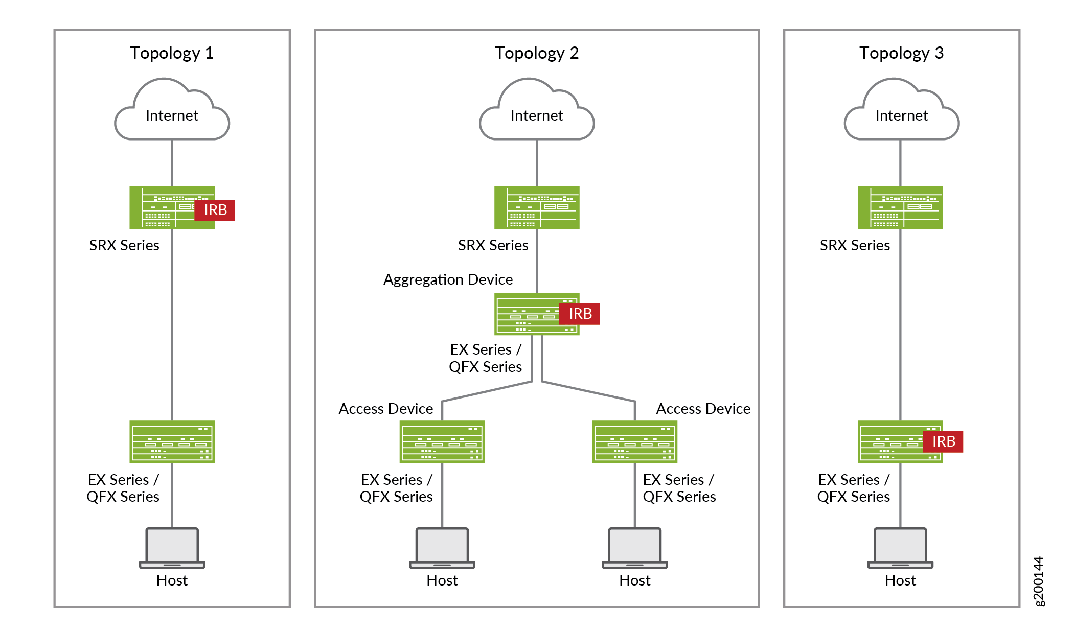
Table 1 provides more detail on these deployment options.
|
Topology 1 |
Topology 2 |
Topology 3 |
|---|---|---|
|
EX Series or QFX Series device as Layer 2 switch |
EX Series or QFX Series device (access switch) as Layer 2 switch EX Series or QFX Series device (aggregation switch) as Layer 3 switch |
EX Series or QFX Series device as Layer 2/Layer 3 switch |
|
SRX Series device as firewall in Layer 3 mode |
SRX Series device as firewall in Layer 3 mode |
SRX Series device as firewall in Layer 3 mode |
|
IRB / VLAN tagging on SRX Series device |
IRB / VLAN tagging on EX Series or QFX Series device (aggregation switch) |
IRB / VLAN tagging on EX Series or QFX Series switch |
-
All interconnecting switch ports (SRX/EX/QFX devices) must be configured in trunk mode, even when there is only one VLAN in use.
-
All switch ports connected to end hosts must be configured in access mode.
-
VLAN names and IDs must be identical on all devices.
For more information, see Appendix 1: Configuration of SRX Series Devices and EX Series Switches.
The lab setup used for this network configuration example was built to support and test all three deployment topologies shown above. This setup is shown in Figure 2.
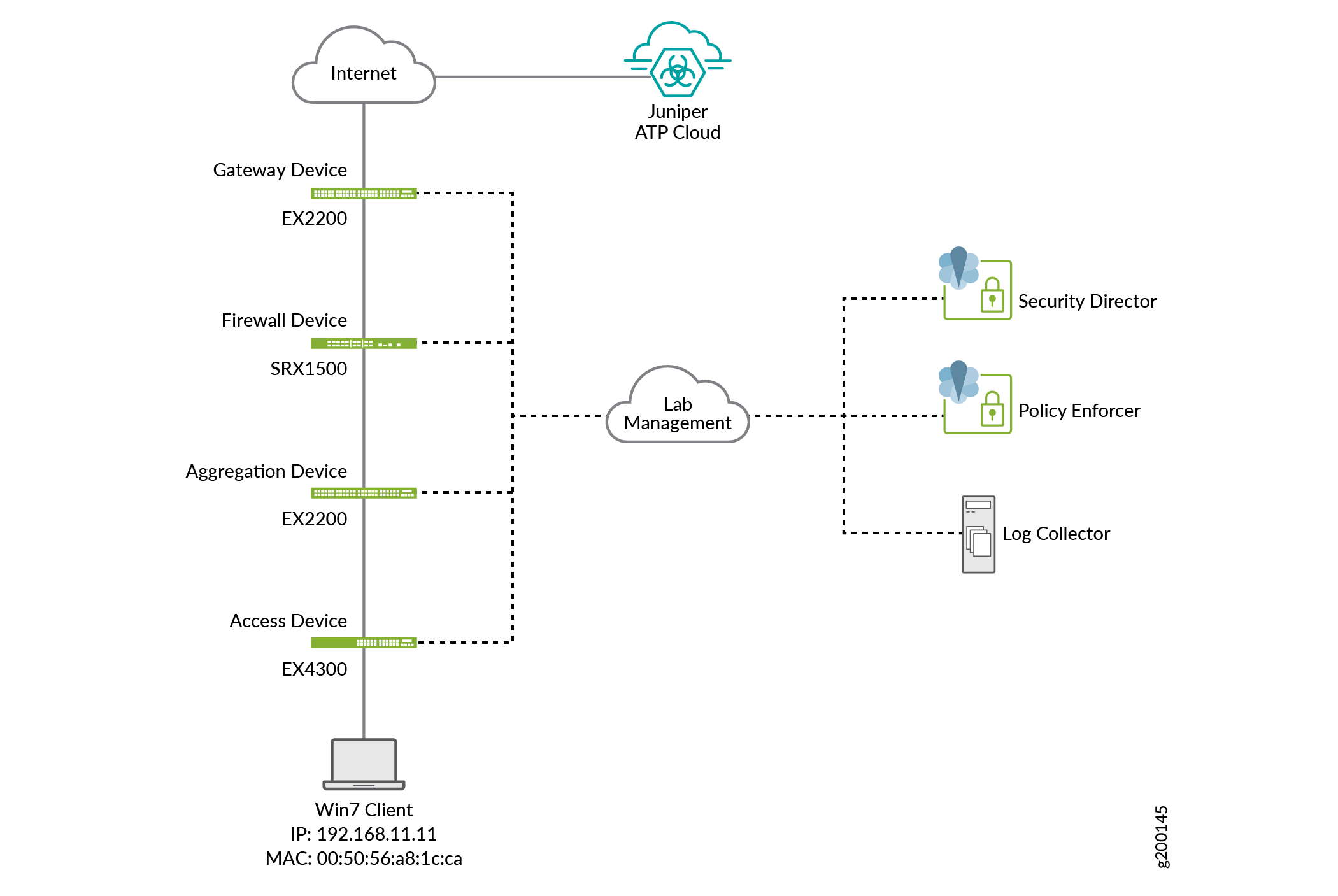
Table 2 and Table 3 show the details of devices, IP addresses, and parameters used in this configuration example.
|
Device |
Function |
Mgmt IP Address |
|---|---|---|
|
SRX1500 (SRX1500-WF) |
Firewall |
10.13.107.186 |
|
EX4300 (EX4300-1) |
Access Switch |
10.13.107.181 |
|
EX2200 |
Aggregation Switch |
10.13.107.188 |
|
Parameter |
Name |
Description |
|---|---|---|
|
Site Name |
Westford-Site |
A site is a grouping of network devices, including firewalls and switches, that contribute to threat prevention. An infected host with IP address 192.168.11.11 is connected to EX4300-1m which belongs to Westford-Site. |
|
Policy Enforcement Group |
JSD |
A policy enforcement group is a grouping of endpoints to which threat prevention policies are applied. In this example, Westford-site is included in policy enforcement group JSD. |
|
Threat Prevention Policy |
TPP |
Threat prevention policies provide protection and monitoring for an assigned policy enforcement group. In this example, policy enforcement group JSD is assigned to threat prevention policy TPP. |
The following set of installation, configuration, and verification steps are required to implement the Juniper Connected Security solution:
-
Install and Configure Junos Space and Security Director
-
Install and configure SRX Series devices and EX/QFX Series switches
-
Download, deploy, and configure the Policy Enforcer virtual machine
-
Connect Policy Enforcer to Security Director
-
Obtain Juniper ATP Cloud license and create ATP Cloud portal account
-
Install the root CA on your ATP Cloud-supported SRX Series devices
-
Configure Juniper ATP Cloud with Policy Enforcer
-
Verify the enrollment of devices on Juniper ATP Cloud
-
Verify Juniper Connected Security functionality once the enrollment is successful
Install and Configure Junos Space and Security Director
- Install Junos Space, Security Director, and Log Collector
- Configure Networking
- Install Policy Enforcer Patch for Security Director, Release 16.2R1
- Install the required DMI schemas on Security Director
Install Junos Space, Security Director, and Log Collector
Step-by-Step Procedure
To Install Junos Space, Security Director, and Log Collector:
-
Download the Junos Space Network Management Platform image from https://www.juniper.net/support/downloads/?p=space#sw.
-
Install Junos Space using the instructions at https://www.juniper.net/documentation/en_US/junos-space16.1/platform/information-products/topic-collections/release-notes/jd0e56.html.
-
Install Junos Security Director as per the instructions at https://www.juniper.net/documentation/en_US/junos-space16.2/information-products/topic-collections/release-notes/js-relnotes-security-design/index.html.
-
Install Log Collector as per the instructions at https://www.juniper.net/documentation/en_US/junos-space16.2/information-products/topic-collections/release-notes/js-relnotes-security-design/index.html..
Configure Networking
Step-by-Step Procedure
To configure basic networking for Junos Space and its components, perform the following tasks:
-
Configure relevant routes, netmask, gateway, DNS, and NTP so that all components except Log Collector can reach the Internet.
-
Ensure all components are in same time zone.
-
Ensure that SSH is enabled.
-
Ensure that Security Director can reach the ATP Cloud server, Policy Enforcer, and all devices.
Install Policy Enforcer Patch for Security Director, Release 16.2R1
Step-by-Step Procedure
To install the Policy Enforcer patch:
-
Download the Policy-Enforcer-16.2R1-Patch.sh file from https://www.juniper.net/support/downloads/?p=sdpe#sw and put it in the /tmp folder of the Junos Space Network Management Platform server.
-
Login to the Junos Space CLI using an SSH or console connection, and change directory to the /tmp folder.
-
Change the permissions of the Policy-Enforcer-16.2R1-Patch.sh file to allow read, write, and execute permissions for everyone, using the following command:
chmod 777 Policy-Enforcer-16.2R1-Patch.sh -
Execute the installation script using the following command:
sh Policy-Enforcer-16.2R1-Patch.shIt may take a few minutes for the script to complete.
Install the required DMI schemas on Security Director
Step-by-Step Procedure
You must download and install the matching Junos OS schemas to manage SRX Series devices. To download and install the correct schemas, perform the following task:
-
Install the missing DMI schemas for Junos OS Releases 15.1X49-D80 and 15.1R5.5 as per the instructions at https://www.juniper.net/documentation/en_US/junos-space16.1/platform/topics/task/configuration/junos-space-network-application-platform-schema-adding.html
-
After the schemas are installed, set them as the default schema for each relevant platform.
Install and Configure SRX Series Devices and EX Series / QFX Series Switches
- Install and Configure SRX Series Devices
- Install and configure EX/QFX Series switches
- Configure Networking
- Device Discovery in Junos Space
Install and Configure SRX Series Devices
Step-by-Step Procedure
To configure SRX device devices:
-
Configure the SRX device(s) per your requirements.
Note:Appendix 1: Configuration of SRX Series Devices and EX Series Switches of this document includes SRX device configurations for all three deployment topologies.
Install and configure EX/QFX Series switches
Step-by-Step Procedure
To configure EX (or QFX) devices:
-
Configure the EX Series and/or QFX Series switches per your requirements.
Note:Appendix 1: Configuration of SRX Series Devices and EX Series Switches of this document includes EX device configurations for all three deployment topologies.
Configure Networking
Step-by-Step Procedure
To configure basic networking on Junos devices, perform the following tasks:
-
On all Junos devices, configure the necessary routing and DNS settings to enable Internet access, as well as connectivity to Junos Space, Policy Enforcer, and the ATP Cloud server.
-
For SRX Series devices, ensure that Internet access is enabled both in-band and out-of-band.
Device Discovery in Junos Space
Step-by-Step Procedure
To add devices to the Junos Space Network Management platform, perform the following tasks:
-
In Junos Space, discover and import the SRX Series, EX Series, and/or QFX Series devices in your environment.
-
In Security Director, assign, publish, and update any existing firewall policies to ensure Security Director and the SRX devices are in sync.
Download, Deploy, and Configure Policy Enforcer Virtual Machine
Procedure
Step-by-Step Procedure
To deploy and configure the Policy Enforcer virtual machine, perform the following tasks:
-
Download the Policy Enforcer virtual machine image from https://www.juniper.net/support/downloads/?p=sdpe to the management station where the vSphere client is installed.
-
On the vSphere client, select File > Deploy OVF Template from the menu bar.
-
Click Browse to locate the OVA file that was downloaded.
-
Click Next and follow the instructions in the installation wizard.
-
Once the installation is complete, login to the virtual machine using
rootandabc123as the username and password, respectively. -
Configure the network settings, NTP information, and customer information, and finish the wizard accordingly.
For more detailed instructions, see https://www.juniper.net/documentation/en_US/release-independent/policy-enforcer/topics/task/installation/policy-enforcer-vm-config.html.
Connect Policy Enforcer to Security Director
Procedure
Step-by-Step Procedure
You must identify the Policy Enforcer virtual machine in Security Director so that they can communicate with each other. To do so, follow these steps:
-
In Security Director, identify the Policy Enforcer virtual machine so that they can communicate with each other.
-
Login to Security Director and select Administration > PE Settings.
-
Enter the IP address of the Policy Enforcer virtual machine and the root password, and click OK.
-
Select Threat Prevention Type as ATP Cloud with PE.
Note:Do not run the wizard/guided setup at this point.
Obtain Juniper ATP Cloud License and Create ATP Cloud Portal Account
Procedure
Step-by-Step Procedure
To obtain a Juniper ATP Cloud license and create an ATP Cloud Web portal account, follow these steps:
-
Juniper ATP Cloud has three service levels: free, basic, and premium. The free license provides limited functionality and is included with the base software. To obtain and install Juniper ATP Cloud basic or premium license, see Managing the Advanced Threat Prevention Cloud License.
For further detail on ATP Cloud service levels and license types, see Advanced Threat Prevention Cloud License Types.
-
Create Juniper ATP Cloud Web portal account by going to https://sky.junipersecurity.net and filling in the required information.
Install the root CA on the ATP Cloud-supported SRX Series devices
This section is required only if you will be enabling HTTPS inspection as part of a malware profile/threat prevention policy.
- Generate Root CA Certificate using Junos OS CLI or OpenSSL
- Configure a CA Profile Group
- Import Root CA Certificate into a Browser
Generate Root CA Certificate using Junos OS CLI or OpenSSL
Step-by-Step Procedure
To generate a root CA certificate using the Junos OS CLI on the SRX device:
-
Generate a PKI public/private key pair for a local digital certificate.
user@host> request security pki generate-key-pair certificate-id ssl-inspect-ca size 2048 type rsa -
Using the key pair, define a self-signed certificate by providing FQDN and other details.
user@host> request security pki local-certificate generate-self-signed certificate-id ssl-inspect-ca domain-name domain-name subject subject email email-id add-ca-constraintOR
Step-by-Step Procedure
To generate a root CA certificate using OpenSSL on a Linux device:
-
Generate a PKI public/private key pair for a local digital certificate.
% openssl req -x509 -nodes -sha256 -days 365 -newkey rsa:2048 -keyout ssl-inspect-ca.key -out ssl-inspect-ca.crt -
Copy the key pair onto the SRX device(s).
-
On the SRX device(s), import the key pair.
user@host> request security pki local-certificate load key ssl-inspect-ca.key filename ssl-inspect-ca.crt certificate-id ssl-inspect-caNote:Use only one of the options above.
Configure a CA Profile Group
Step-by-Step Procedure
To configure a CA profile group:
-
Create the CA profile.
user@host# set security pki ca-profile ssl-inspect-ca ca-identity ssl-inspect-causer@host# commit -
The Junos OS provides a default list of trusted CA certificates that you can load on your system using the default command option.
user@host> request security pki ca-certificate ca-profile-group load ca-group-name All-Trusted-CA-Def filename defaultDo you want to load this CA certificate ? [yes,no] (no) yes Loading 155 certificates for group 'All-Trusted-CA-Def'. All-Trusted-CA-Def_1: Loading done. All-Trusted-CA-Def_2: Loading done. All-Trusted-CA-Def_3: Loading done. All-Trusted-CA-Def_4: Loading done. All-Trusted-CA-Def_5: Loading done. ... -
Verify that the All-Trusted-CA-Def certificates are loaded.
user@host> show security pki ca-certificate brief... Certificate identifier: All-Trusted-CA-Def_1 ...
Import Root CA Certificate into a Browser
Step-by-Step Procedure
First, export the root CA certificate:
-
On the SRX device, export the certificate to a .pem file.
user@host> request security pki local-certificate export certificate-id ssl-inspect-ca type pem filename /var/tmp/ssl-inspect-ca.pem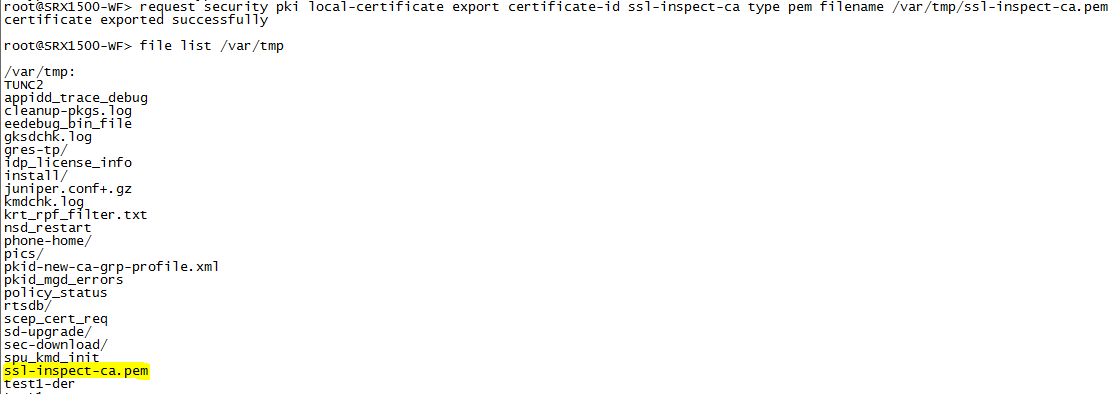
-
Transfer the .pem file to your Windows client.
Note:If you are using the Linux device with OpenSSL, the certificate is already on the device and no action is required.
Step-by-Step Procedure
Then import certificate into a browser:
-
On the Windows client, instruct the browser to trust the CA root certificate.
Internet Explorer (version 8.0):
-
From the Tools menu, choose Internet Options.
-
On the Content tab, click Certificates.
-
Select the Trusted Root Certification Authorities tab and click Import.
-
In the Certificate Import Wizard, navigate to the required root CA certificate and select it.
Firefox (version 39.0):
-
From the Tools menu, choose Options.
-
From the Advanced menu, select the Certificates tab and click View Certificate.
-
In the Certificate Manager window, select the Authorities tab and click Import.
-
Navigate to the required root CA certificate and select it.
Google Chrome (version 45.0):
-
From the Settings menu, choose Show Advanced Settings.
-
From the Advanced menu, select the Certificates tab and click View Certificate.
-
Under HTTPS/SSL, click Manage Certificates.
-
In the Certificate window, select Trusted Root Certification Authorities and click Import.
-
In the Certificate Import Wizard, navigate to the required root CA certificate and select it.
More details on the steps in this section can be found at: https://www.juniper.net/documentation/en_US/junos/topics/task/configuration/ssl-proxy-workflow-configuring.html
OR
-
Step-by-Step Procedure
-
On the Linux device, import the certificate into the browser.
% sudo cp ssl-inspect-ca.crt /usr/local/share/ca-certificates/ ssl-inspect-ca.crt% sudo update-ca-certificates
Configure Juniper Connected Security with Juniper ATP Cloud and Policy Enforcer
Procedure
Step-by-Step Procedure
The tasks required to configure Juniper Connected Security include:
-
Configure a secure fabric
-
Define a site and add endpoints to it (switches and firewalls)
-
Configure policy enforcement groups
-
Create a threat prevention policy
-
Apply threat prevention policies to policy enforcement groups
If you are using Policy Enforcer for threat prevention with Juniper ATP Cloud, Guided Setup is the most efficient way to complete the initial configuration. The Guided Setup process offers four steps for configuring Juniper Connected Security with Juniper ATP Cloud, and is used below.
To perform the configuration without the guided setup, see Configuring Juniper Connected Security with ATP Cloud and Policy Enforcer (Without Guided Setup).
This configuration example implements topology 1 from Overview and Topology.
The screenshots used in this section have been updated to Junos Space Security Director Release 17.1R1.
-
In Security Director, go to Configure > Guided Setup > Threat Prevention.
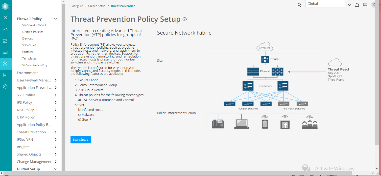
-
Click Start Setup and follow the wizard.
-
Create a secure fabric site that includes all the relevant SRX Series and EX Series (or QFX) devices in the network.
A secure fabric is a collection of sites which contain network devices (switches, routers, firewalls, and other security devices) used in policy enforcement groups.
-
Create a policy enforcement group by selecting the relevant LAN subnets for which you want to enable policy enforcement.
A policy enforcement group is a grouping of endpoints to which threat prevention policies are applied.
In this step, you need to determine the type of endpoints you are including in your policy enforcement group: IP address, subnet, or location. Note that endpoints cannot belong to multiple policy enforcement groups.
-
Add the ATP Cloud realm by providing the relevant details from your ATP Cloud account.
Before you configure the ATP Cloud realm, ensure that you:
-
Have an ATP Cloud account with an associated license.
-
Understand which type of ATP Cloud license you have: free, basic, or premium. The license controls which ATP Cloud features are available.
See Obtain Juniper ATP Cloud License and Create ATP Cloud Portal Account for more details.
-
Know which region will be covered by the realm you are creating. You must a select a region when you configure a realm.
-
-
Verify that the ATP Cloud realm has been added. The value 1 should appear in the Perimeter Firewall in Sites column, indicating that ATP Cloud has detected the SRX device.
If the realm addition is not successful, it means there is a network issue and Security Director is unable to reach Internet. Ensure all devices/components can reach the Internet and each other.
-
Create a threat prevention policy.
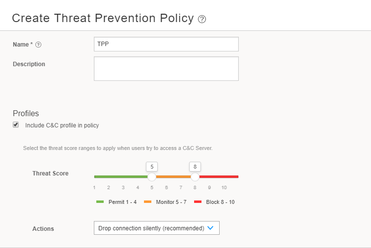
Threat prevention policies provide protection and monitoring for selected threat profiles, including command & control servers, infected hosts, and malware.
In this step, you need to:
-
Determine the type of profile you will use for this policy: command & control server, infected hosts, or malware. You can select one or more threat profiles in a policy.
-
Determine which action to take if a threat is found.
-
Know which policy enforcement group you will add to this policy.
-
-
Add a profile for HTTP file downloads and SMTP attachments.
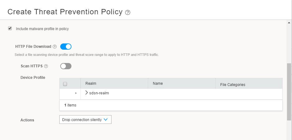
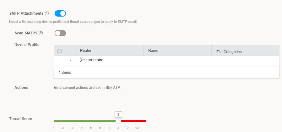
This profile indicates which file types need to be scanned for threats. In the Device Profile area, expand the realm and select the required profile.
-
Assign the threat prevention policy to the desired policy enforcement group by clicking Assign to Groups.
-
Select the policy enforcement group and click OK.
-
The system performs a rule analysis, and prepares device configurations that include the threat prevention policies.
-
Once the analysis is complete, instruct the system to push the updated policy to the SRX Series devices by clicking the Update button.
-
When the push is complete, the system returns to the Policies page.
Verification
- Verify the Enrollment of Devices in Juniper ATP Cloud on SRX Series Device
- Verify the Enrollment of Policy Enforcer and SRX Series Devices in Juniper ATP Cloud
- Verify the Enrollment of Devices with Juniper ATP Cloud in Security Director
- Test Juniper Connected Security Functionality
- Verify Juniper Connected Security Functionality Using the Security Director Logs
- Verify Juniper Connected Security Functionality on the EX Series Switch
- Verify Juniper Connected Security Functionality on the SRX Series Device
- Verifying the Configuration on the SRX Series Device
- Monitoring Juniper Connected Security Functionality on the SRX Series Device
- View Compromised Hosts and Other Details
- Verifying Host Tracking
Verify the Enrollment of Devices in Juniper ATP Cloud on SRX Series Device
Purpose
Verify that the SRX Series device is connected to the ATP Cloud server.
Action
On the SRX device, use the show services advanced-anti-malware status CLI command.
user@host> show services advanced-anti-malware status
 Server hostname:
 srxapi.us-west-2.sky.junipersecurity.net
  Server port: 443
    Control Plane:
      Connection time: 2017-10-15 23:53:31 UTC
      Connection status: Connected
    Service Plane:
      fpc0
        Connection active number: 11
        Connection retry statistics: 872
Meaning
The output displays the Connection status as
Connected. The Server hostname field displays the
ATP Cloud server hostname.
Verify the Enrollment of Policy Enforcer and SRX Series Devices in Juniper ATP Cloud
Purpose
Verify that Policy Enforcer and the SRX Series device are enrolled with Juniper ATP Cloud.
Action
In the ATP Cloud Web UI, navigate to the Enrolled Devices page and review the connection information for enrolled devices, including serial number, model number, tier level (free, basic, premium) enrollment status in ATP Cloud, last telemetry activity, and last activity seen.
Meaning
The Host field displays the enrolled firewall detail (SRX1500-WF). You
can click the serial number for more details.
Verify the Enrollment of Devices with Juniper ATP Cloud in Security Director
Purpose
Verify that the SRX Series device is enrolled with Juniper ATP Cloud in Security Director.
Action
Navigate to Devices > Security Devices in Security Director.
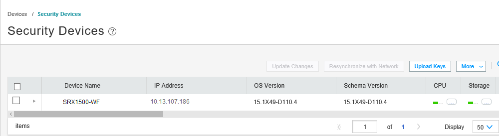
On the Security Devices page, the device’s name, IP address, OS version are displayed. You can scroll right to get more details such as ATP Cloud realm, serial number, assigned devices, and so on.
You can alternatively click the Detailed View icon next to the device name to get more details about the device.
Meaning
The ATP Cloud realm’s name displayed under the ATP Realm field confirms enrollment of the device with the ATP Cloud realm.
Test Juniper Connected Security Functionality
Purpose
With the Juniper Connected Security solution configured, verify how it detects a problem and reacts to it.
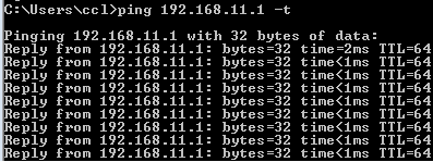
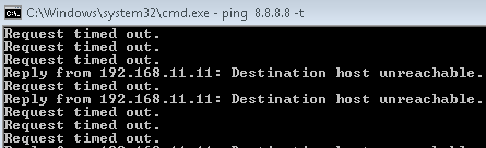
In this scenario, an end host (192.168.11.11) on the LAN simulates a threat by contacting (pinging) a C&C server (192.0.2.1). This event is determined to exceed the threat prevention policy’s threat score threshold.
Action
Verify the connectivity between end hosts to endpoints on the LAN and Internet using the Ping command before and after the attack.
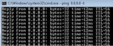
Before the attack, the end host starts continuous pings to endpoints on the LAN and Internet.
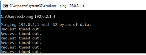
The end host pings the C&C server.
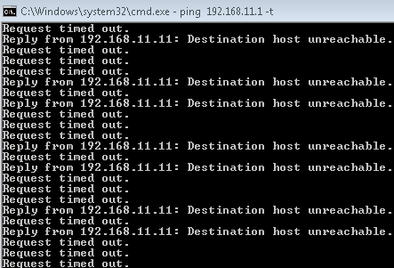
Verify that connectivity to the endpoint on the LAN is blocked after the attack.
Confirm that the end host can no longer reach the Internet.
Meaning
All ping sessions show that the traffic is blocked after the threat is detected, which confirms that the Juniper Connected Security solution is working properly.
Verify Juniper Connected Security Functionality Using the Security Director Logs
Purpose
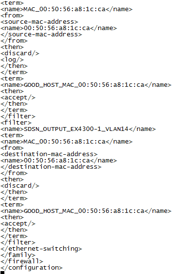
Verify that the firewall filter has been created and applied to the switch where the end host is attached.
Action
Check the Security Director logs (/var/log/jboss/servers/server1/SECI.log).

Meaning
The logs confirm that firewall filters have been automatically created and pushed to the access switch to block the end host.
Verify Juniper Connected Security Functionality on the EX Series Switch
Purpose
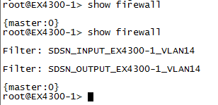
Verify that the firewall filters have been applied to the switch where the end host is attached.
Action
Run the show firewall command on the switch.
Meaning
The output confirms that the firewall filters are applied on the access switch to block the end host.
Verify Juniper Connected Security Functionality on the SRX Series Device
Purpose
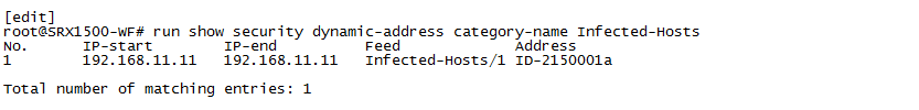
Display the list of hosts within your network that may have been compromised and require attention.
Action
Use the show security dynamic-address category-name Infected-Hosts command on the SRX device.
Meaning
The output shows that the ATP Cloud infected host feed containing the end host’s IP address has been successfully downloaded, resulting in the SRX device taking action to block Internet access for the infected host.
Verifying the Configuration on the SRX Series Device
Purpose
Verify that the threat prevention policy has been pushed to SRX Series device.
Action
Run the show security and show services commands, and
verify that the following configuration elements exist on the SRX device. These
configuration changes can also be seen through Security Director.
Your output may look slightly different as the outputs are dependent on your setup and location.


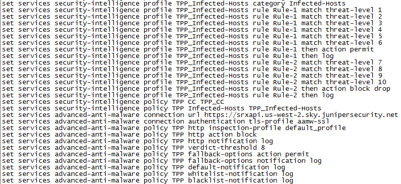
Meaning
The new policies, security intelligence feed points, and advanced malware URL confirm that the threat prevention policy has been pushed to SRX Series device.
Monitoring Juniper Connected Security Functionality on the SRX Series Device
Purpose
Display a summary of session information for the various profiles in use.
Action
Use the show services security-intelligence statistics CLI command to view a quick report.
user@host> show services security-intelligence statistics
Category Whitelist:
  Profile Whitelist:
    Total processed sessions: 10716
    Permit sessions:          0
Category Blacklist:
  Profile Blacklist:
    Total processed sessions: 10716
    Block drop sessions:      0
Category CC:
  Profile TPP_CC:
    Total processed sessions: 10171
    Permit sessions:          0
    Block drop sessions:      0
    Block close sessions:     0
    Close redirect sessions:  0
Category Infected-Hosts:
  Profile TPP_Infected-Hosts:
    Total processed sessions: 10716
    Permit sessions:          0
    Block drop sessions:      12
    Block close sessions:     0
Meaning
The Category Infected-Hosts field provides the data on sessions
processed (blocked/dropped) through the different profiles such as Profile
TPP_CC and Profile TPP_Infected-Hosts. In this sample
output, the Permit sessions field confirms that no sessions were
allowed when the threat was detected.
View Compromised Hosts and Other Details
Purpose
View information about current threats to a specific host by time frame.
Action
Navigate to Monitor > Threat Prevention > Hosts in Security Director, or Monitor > Hosts in theATP portal.
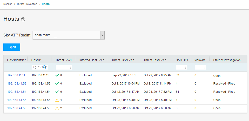
Meaning
The Hosts page lists compromised hosts and their associated threat levels. The output confirms that ATP Cloud and Security Director have detected the infected host. From here, you can monitor and mitigate malware detections on a per host basis.
Verifying Host Tracking
Purpose
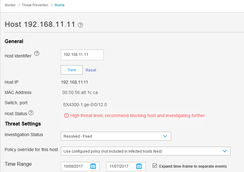
When the infected host (192.168.11.11) physically moves to another location (connected to EX4300-2), verify that the Policy Enforcer learns the new IP address of the host, updates its MAC address-to-IP address binding, and continues to quarantine the host.
Action
Navigate to Monitor > Threat Prevention > Hosts in Security Director.
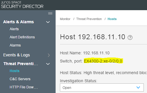
Meaning
The screenshots confirm that the infected host has moved to new location, is attached to a different switch (EX4300-2), and has a new IP address. They also confirm that the EX4300-2 switch and ATP Cloud have detected the move, continued to recognize the host as infected, and continued to quarantine it.
Switch EX4300-2 was not included in the earlier configuration steps, as this switch is part of the Topology 2 implementation option. Configuration information for this switch can be found at EX4300-2 Access Switch Configuration.