Managing the EVPN-VXLAN Fabric
Up to this point in the configuration of the EVPN-VXLAN fabric, we have used a topology with three virtual networks and one access layer switch that simulates an access closet. Use this section to add a second access switch and a new virtual network.
These configuration examples use the same devices you configured in the How to Configure a Campus Network using EVPN Multihoming configuration example.
Add an Access Layer Switch
Requirements
Overview
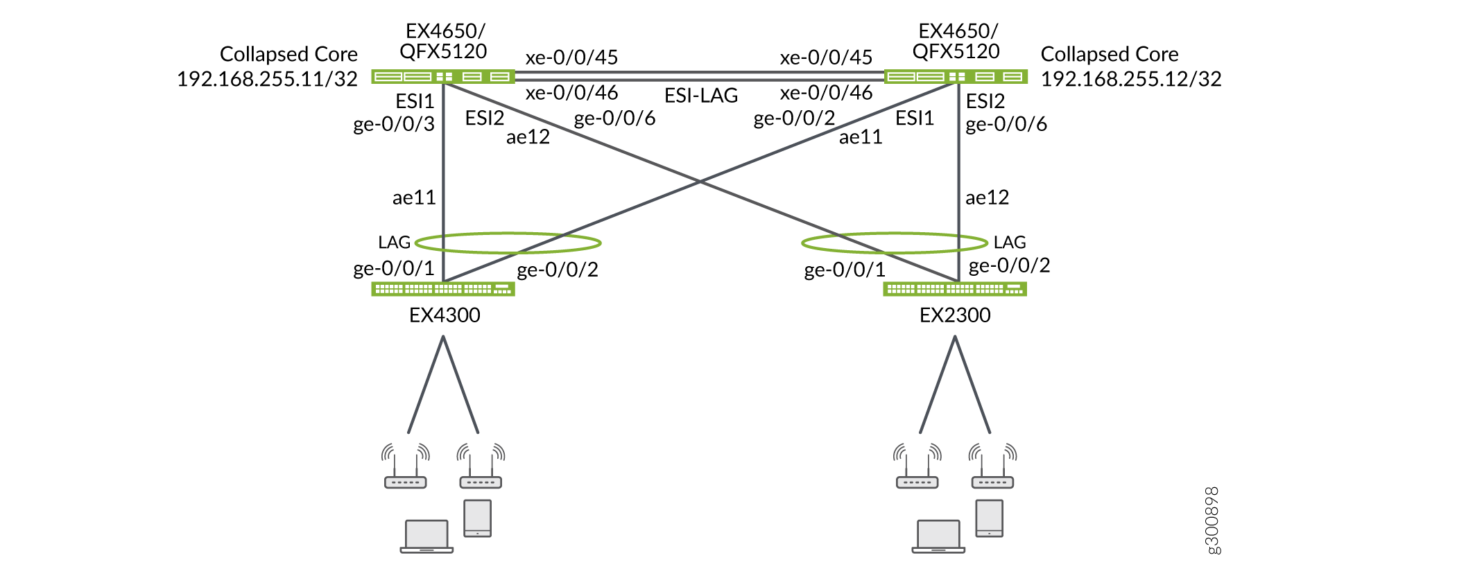
Use this section to add a new access layer switch (Access Switch 2) to the network that is multihomed to the same collapsed core switches. Figure 1 shows the physical topology with Access Switch 2.

Configuration
This section shows the step-by-step configuration procedures to add a new access Switch (Access Switch 2) to your network.
Collapsed Core 1 Configuration
Step-by-Step Procedure
Specify the interface to include in the aggregated Ethernet bundle.
set interfaces ge-0/0/6 description "Access Switch 2"
set interfaces ge-0/0/6 ether-options 802.3ad ae12
Configure the aggregated Ethernet interface to the new access layer switch and increase the ethernet device-count to two to support the additional aggregated Ethernet interface.
set chassis aggregated-devices ethernet device-count 2
set interfaces ae12 description To-Access-2
set interfaces ae12 mtu 9200
set interfaces ae12 esi 00:11:11:11:11:11:11:11:11:02
set interfaces ae12 esi all-active
set interfaces ae12 aggregated-ether-options lacp active
set interfaces ae12 aggregated-ether-options lacp periodic fast
set interfaces ae12 aggregated-ether-options lacp system-id 00:40:00:00:00:02
set interfaces ae12 unit 0 family ethernet-switching interface-mode trunk
set interfaces ae12 unit 0 family ethernet-switching vlan members VLAN-201
set interfaces ae12 unit 0 family ethernet-switching vlan members VLAN-202
set interfaces ae12 unit 0 family ethernet-switching vlan members VLAN-101
set interfaces ae12 unit 0 family ethernet-switching vlan members VLAN-102
set interfaces ae12 unit 0 family ethernet-switching vlan members VLAN-301
set interfaces ae12 unit 0 family ethernet-switching vlan members VLAN-302
Collapsed Core 2 Configuration
Step-by-Step Procedure
Specify the interface to include in the aggregated Ethernet bundle.
set interfaces ge-0/0/6 description "Access Switch 2"
set interfaces ge-0/0/6 ether-options 802.3ad ae12
Configure the aggregated Ethernet interface to the new access layer switch and increase the ethernet device-count to two to support the additional aggregated Ethernet interface.
set chassis aggregated-devices ethernet device-count 2
set interfaces ae12 description To-Access-2
set interfaces ae12 mtu 9200
set interfaces ae12 esi 00:11:11:11:11:11:11:11:11:02
set interfaces ae12 esi all-active
set interfaces ae12 aggregated-ether-options lacp active
set interfaces ae12 aggregated-ether-options lacp periodic fast
set interfaces ae12 aggregated-ether-options lacp system-id 00:40:00:00:00:02
set interfaces ae12 unit 0 family ethernet-switching interface-mode trunk
set interfaces ae12 unit 0 family ethernet-switching vlan members VLAN-201
set interfaces ae12 unit 0 family ethernet-switching vlan members VLAN-202
set interfaces ae12 unit 0 family ethernet-switching vlan members VLAN-101
set interfaces ae12 unit 0 family ethernet-switching vlan members VLAN-102
set interfaces ae12 unit 0 family ethernet-switching vlan members VLAN-301
set interfaces ae12 unit 0 family ethernet-switching vlan members VLAN-302
(Optional) Enable IGMP snooping to constrain the flooding of IPv4 multicast traffic on the VLANs.
set protocols igmp-snooping vlan VLAN-201 interface ae11.0 multicast-router-interface
set protocols igmp-snooping vlan VLAN-202 interface ae11.0 multicast-router-interface
set protocols igmp-snooping vlan VLAN-101 interface ae11.0 multicast-router-interface
set protocols igmp-snooping vlan VLAN-102 interface ae11.0 multicast-router-interface
set protocols igmp-snooping vlan VLAN-301 interface ae11.0 multicast-router-interface
set protocols igmp-snooping vlan VLAN-301 interface ae11.0 multicast-router-interface
set protocols igmp-snooping vlan VLAN-201 interface ae12.0 multicast-router-interface
set protocols igmp-snooping vlan VLAN-202 interface ae12.0 multicast-router-interface
set protocols igmp-snooping vlan VLAN-101 interface ae12.0 multicast-router-interface
set protocols igmp-snooping vlan VLAN-102 interface ae12.0 multicast-router-interface
set protocols igmp-snooping vlan VLAN-301 interface ae12.0 multicast-router-interface
set protocols igmp-snooping vlan VLAN-301 interface ae12.0 multicast-router-interface
Access Switch 2 Configuration
Step-by-Step Procedure
Configure the physical LAG interface.
set interfaces ge-0/0/1 description "to campus-tme-ex4650-01"
set interfaces ge-0/0/1 ether-options 802.3ad ae12
set interfaces ge-0/0/2 description "to campus-tme-ex4650-02"
set interfaces ge-0/0/2 ether-options 802.3ad ae12
Configure the LAG interface to the new access layer switch.
set chassis aggregated-devices ethernet device-count 1
set interfaces ae12 aggregated-ether-options lacp active
set interfaces ae12 aggregated-ether-options lacp periodic fast
set interfaces ae12 unit 0 family ethernet-switching interface-mode trunk
set interfaces ae12 unit 0 family ethernet-switching vlan members 101-102
set interfaces ae12 unit 0 family ethernet-switching vlan members 201-202
set interfaces ae12 unit 0 family ethernet-switching vlan members 301-302
(Optional) Enable IGMP snooping to constrain the flooding of IPv4 multicast traffic on the VLANs.
set protocols igmp-snooping vlan VLAN-201 interface ae12.0 multicast-router-interface
set protocols igmp-snooping vlan VLAN-202 interface ae12.0 multicast-router-interface
set protocols igmp-snooping vlan VLAN-101 interface ae12.0 multicast-router-interface
set protocols igmp-snooping vlan VLAN-102 interface ae12.0 multicast-router-interface
set protocols igmp-snooping vlan VLAN-301 interface ae12.0 multicast-router-interface
set protocols igmp-snooping vlan VLAN-301 interface ae12.0 multicast-router-interface
