Help us improve your experience.

Let us know what you think.

Do you have time for a two-minute survey?


Enhanced Optimized Intersubnet Multicast (OISM) Implementation

SUMMARY Configure enhanced optimized intersubnet multicast (OISM) in a scaled EVPN-VXLAN edge-routed bridging (ERB) overlay fabric when the OISM leaf devices host a large number of diverse revenue VLANs.

In EVPN-VXLAN edge-routed bridging (ERB) overlay fabric designs, the leaf devices forward traffic within tenant VLANs and route traffic between tenant VLANs. To support efficient multicast traffic flows in scaled ERB overlay fabrics, we support optimized intersubnet multicast (OISM) with both internal and external multicast sources and receivers.

Regular OISM and Enhanced OISM Differences

We refer to our original OISM implementation as regular OISM. Regular OISM uses a symmetric bridge domains OISM model that requires you to configure all revenue VLANs (the tenant VLANs) in the network on all OISM leaf devices. See Optimized Intersubnet Multicast (OISM) with Assisted Replication (AR) for Edge-Routed Bridging Overlays in this guide for an example of a regular OISM configuration. Due to the symmetric VLANs configuration requirement, we also call regular OISM the "bridge domains everywhere" (BDE) version of OISM.

Enhanced OISM uses an asymmetric bridge domains OISM model in which you don't need to configure all revenue VLANs in the network on all OISM devices. On each leaf device that is not a multihoming peer with another leaf device, you can configure only the revenue VLANs that device hosts. However, the design still requires you to configure matching revenue VLANs on leaf devices that are multihoming peers. Enhanced OISM has some operational differences from regular OISM that support the asymmetric bridge domains model, but most of the configuration elements you need to set up are the same. Because you can configure the VLANs asymmetrically, we also call enhanced OISM the "bridge domains not everywhere" (BDNE) version of OISM.

Note:

Multihoming peer leaf devices are leaf devices that share an Ethernet segment (ES) for an attached multihomed client host, customer edge (CE) device, or top-of-rack (TOR) device.

The enhanced OISM asymmetric bridge domain model enables OISM to scale well when your network has leaf devices that host a large number of diverse revenue VLANs.

This example shows enhanced OISM configuration elements and verification steps tested in our scaled reference environment. We describe a few use cases here that highlight the main differences between regular OISM mode and enhanced OISM mode.

Enhanced OISM Use Cases Overview

The enhanced OISM use cases included in this example don't include full device configurations. Instead, we focus on the sections of the configuration for the test environment differences and the enhanced OISM operational differences compared to the regular OISM example in Optimized Intersubnet Multicast (OISM) with Assisted Replication (AR) for Edge-Routed Bridging Overlays, such as:

  • Using EBGP for the overlay peering in the EVPN core network (instead of IBGP, which the regular OISM example configuration environment uses for the overlay peering).

  • Configuring the same set of revenue VLANs only on multihoming peer leaf devices, and configuring different sets of revenue VLANs on the other OISM leaf devices.

  • Configuring the VRF instances and IRB interfaces on leaf devices that host different sets of revenue VLANs.

  • Enabling IPv6 multicast with MLDv1 any-source multicast (ASM) or MLDv2 source-specific multicast (SSM), which is supported with regular OISM but wasn't included in the regular OISM configuration example.

  • Verifying behaviors specific to enhanced OISM operation (see Operational Differences in Enhanced OISM Mode).

Refer to the regular OISM example in Optimized Intersubnet Multicast (OISM) with Assisted Replication (AR) for Edge-Routed Bridging Overlays for complete details on configuring all of the required elements that are common for both regular OISM and enhanced OISM, such as:

  • EVPN fabric interfaces

  • Underlay and overlay peering (except here we cover EBGP for the overlay peering)

  • EVPN MAC-VRF instances

  • Multicast protocols—IGMP, IGMP snooping, MLD, MLD snooping, Protocol Independent Multicast (PIM)

  • The SBD, the revenue VLANs, and their corresponding IRB interfaces

  • The tenant VRF instances

  • OISM device roles—Server leaf, or border leaf as a PIM EVPN gateway (PEG) for exchanging multicast traffic from and to external sources and external receivers

  • Interfaces to and from an external PIM domain

Configuration Differences in Enhanced OISM Mode

You configure enhanced OISM in almost the same way that you configure regular OISM, using the same statements to set up the OISM environment. The only differences are:

  • To enable enhanced mode instead of regular mode, configure the enhanced-oism option at the [edit forwarding-options multicast-replication evpn irb] hierarchy level instead of configuring the oism option that enables regular OISM.

  • Configure the virtual routing and forwarding (VRF) instances on the OISM leaf devices with the revenue VLANs each device hosts. On each set of multihoming peer leaf devices, however, be sure to configure the same set of revenue VLANs, which should be a combination of all revenue VLANs used by the receivers behind those peer leaf devices.

  • Configure an OSPF area for server leaf device connectivity on the SBD. With enhanced OISM, the server leaf devices need Layer 3 connectivity to route source traffic onto the SBD for east-west traffic. As a result, in each tenant VRF, you configure an OSPF area on the server leaf devices with the SBD IRB interface in active mode to form adjacencies on the SBD. You configure the other interfaces in OSPF passive mode.

    Note that on the OISM border leaf devices, for both regular and enhanced OISM, we require you to configure an OSPF area in each tenant VRF with the following interfaces:

    • The SBD IRB interface, in OSPF active mode

    • The PEG interface that provides access to external multicast sources and receivers, in OSPF active mode

    • The remaining interfaces in the VRF, including the revenue VLAN IRB interfaces, in OSPF passive mode

Operational Differences in Enhanced OISM Mode

The main operational differences in enhanced OISM mode operation compared to regular OISM mode operation are:

  • East-west traffic from internal sources—The ingress leaf devices forward east-west multicast source traffic on the source VLAN only to their multihoming peer leaf devices with which they share at least one Ethernet segment. For all other OISM leaf devices, the ingress leaf devices route the source traffic only on the supplemental bridge domain (SBD), even if those other devices host the source VLAN. Then each leaf device locally routes the traffic from the SBD to the destination VLAN.

    Conversely, regular OISM sends multicast traffic from internal sources only on the source VLAN. Then each leaf device locally forwards the traffic on the source VLAN or routes the traffic to the destination VLAN. Only the border leaf devices route traffic on the SBD; the border leaf devices use the SBD to support multicast flows from external sources to receivers inside the EVPN fabric.

    Note:

    Enhanced OISM, like regular OISM, requires you to enable IGMP snooping or MLD snooping, so the ingress leaf device for a multicast flow sends the traffic only toward other OISM leaf devices with receivers that subscribed to (sent an IGMP or MLD join for) that flow.

  • North-south traffic from internal sources toward external receivers—The ingress leaf devices generate EVPN Type 10 Selective P-router Multicast Service Interface (S-PMSI) Auto-Discovery (A-D) routes for internal multicast (S,G) sources and groups.

    The OISM border leaf devices act as PIM EVPN gateway (PEG) devices to connect to external multicast sources and receivers. The PEG devices need to perform PIM source registration only for multicast sources inside the EVPN network, so they look for and only do PIM registration for the sources in advertised S-PMSI A-D routes.

  • Enhanced OISM limitation for data packets with a time to live (TTL) of 1—Enhanced OISM routes most multicast traffic on the SBD rather than on the source VLAN (even if the destination device hosts the source VLAN). The TTL value on multicast data packets routed to the SBD and then to the destination VLAN will have the packet TTL decremented more than once. As a result, packets with TTL=1 won't reach the receivers. This limitation applies to traffic for any multicast groups other than 224.0.0.0/24 (for IPv4 multicast) and ff02::/16 (for IPv6 multicast).

For more details on the operational differences between regular OISM and enhanced OISM mode, see the following pages in the EVPN User Guide:

For full details on all OISM concepts, components, configuration and operation, see Optimized Inter-Subnet Multicast in EVPN Networks.

Configure and Verify the EBGP Underlay and EBGP Overlay Peering

In the EVPN-VXLAN fabric configuration for regular OISM in Optimized Intersubnet Multicast (OISM) with Assisted Replication (AR) for Edge-Routed Bridging Overlays, we configure the underlay peering with EBGP and the overlay peering with IBGP. However, in this example for enhanced OISM, the EVPN-VXLAN reference architecture test environment uses EBGP for both the underlay peering and the overlay peering. See Figure 1.

Note:

We support both IPv4 and IPv6 multicast data traffic over the IPv4 underlay and overlay in this configuration.

Figure 1: Enhanced OISM EVPN-VXLAN Fabric—EBGP Underlay and EBGP Overlay Peering Enhanced OISM EVPN-VXLAN Fabric—EBGP Underlay and EBGP Overlay Peering

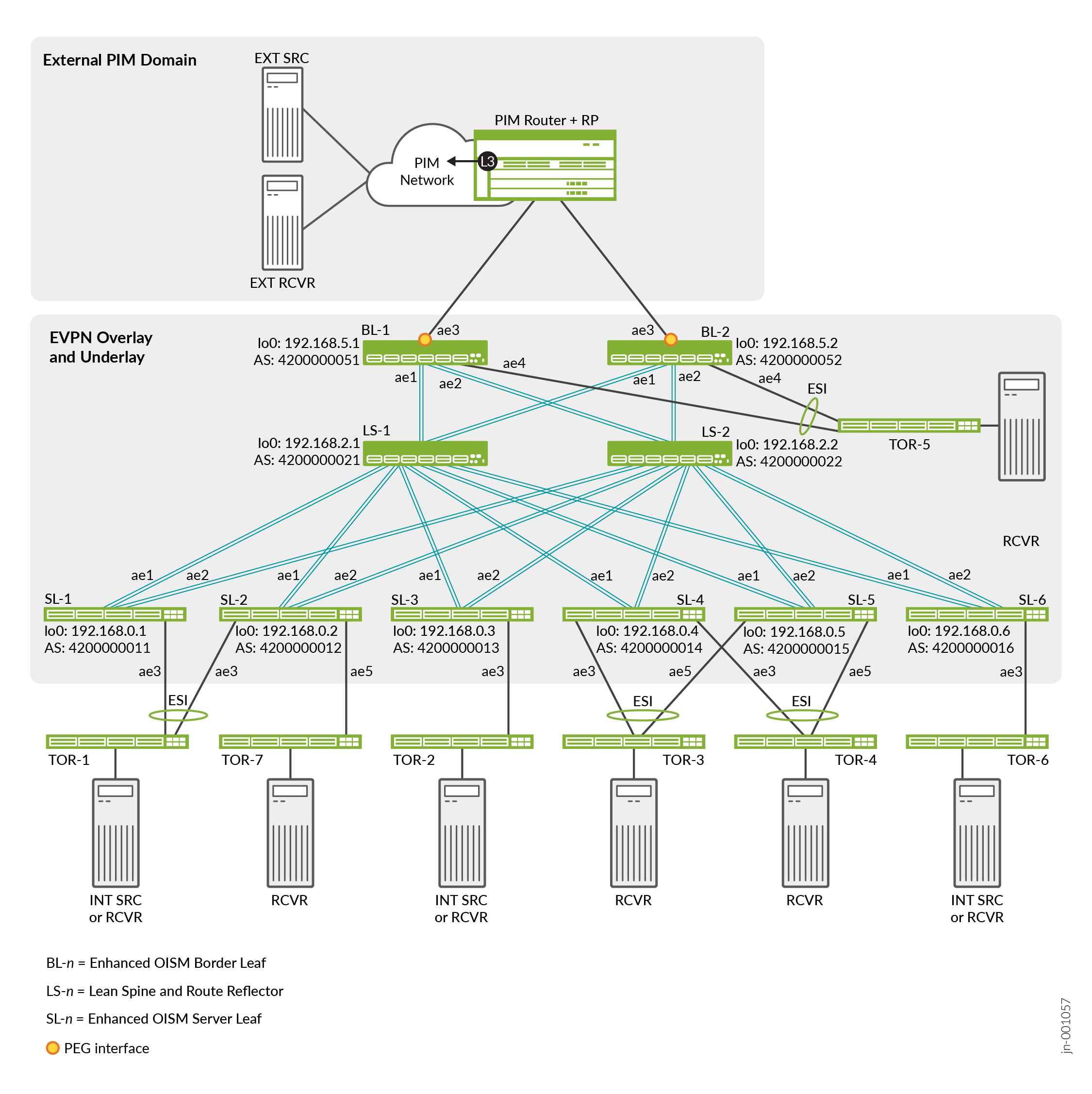
All of the OISM server leaf devices (SL-n) and border leaf devices (BL-n) peer with the lean spine devices LS-1 and LS-2 in a full mesh spine and leaf configuration. See:

  • Figure 1 for the EVPN core interface names, device loopback addresses, and AS numbers.

  • Table 1 for the corresponding subnet addresses for the underlay peering interfaces—all interface addresses are .0 on the spine device side and .1 on the leaf device side.

Table 1: Enhanced OISM Interfaces for Spine and Leaf Peering

Leaf Device

Spine Device

Interface

Underlay Subnet

SL-1

192.168.0.1

LS-1

ae1

172.16.1.0/31

LS-2

ae2

172.16.3.0/31

SL-2

192.168.0.2

LS-1

ae1

172.16.2.0/31

LS-2

ae2

172.16.4.0/31

SL-3

192.168.0.3

LS-1

ae1

172.16.5.0/31

LS-2

ae2

172.16.6.0/31

SL-4

192.168.0.4

LS-1

ae1

172.16.7.0/31

LS-2

ae2

172.16.9.0/31

SL-5

192.168.0.5

LS-1

ae1

172.16.8.0/31

LS-2

ae2

172.16.10.0/31

SL-6

192.168.0.6

LS-1

ae1

172.16.15.0/31

LS-2

ae2

172.16.16.0/31

BL-1

192.168.5.1

LS-1

ae1

172.16.11.0/31

LS-2

ae2

172.16.13.0/31

BL-2

192.168.5.2

LS-1

ae1

172.16.12.0/31

LS-2

ae2

172.16.14.0/31

Configure EBGP Underlay Peering

The underlay configuration is similar to the regular OISM EBGP underlay configuration example, but the enhanced OISM test environment has a few interface subnet differences. On each leaf device, configure EBGP for the underlay peering with neighbor devices LS-1 and LS-2. For example:

SL-1:

Substitute the corresponding interface IP addresses and AS numbers when you configure the underlay on the other OISM leaf devices.

Configure EBGP Overlay Peering

On each leaf device, configure the EBGP overlay peering with neighbor devices LS-1 and LS-2. For example:

SL-1:

Substitute the corresponding device loopback addresses and AS numbers when you configure the overlay on the other OISM leaf devices.

Verify Underlay and Overlay Peering

To verify the EBGP underlay and overlay peering on SL-1 (lo0: 192.168.0.1, AS 4200000011), for example, look for the following in the output from the show bgp neighbor command:

  • Underlay peering on:

    • LS-1: Subnet 172.16.1.0/31

    • LS-2: Subnet 172.16.3.0/31

  • Overlay peering with:

    • LS-1: lo0 192.168.2.1, AS 4200000021

    • LS-2: lo0 192.168.2.2, AS 4200000022

Run the command on each OISM leaf devices and look for the corresponding interconnecting subnets and overlay device loopback addresses.

Configure the EVPN MAC-VRF Instance and Enable Enhanced OISM

You configure the same EVPN MAC-VRF instance named MACVRF-1 on all OISM server leaf and OISM border leaf devices, with only a few differences for parameters that depend on which device you're configuring. In later sections for different use case configurations, you add the VLANs, corresponding IRB interfaces, and VXLAN VNI mappings instance that are specific to that use case.

  1. Configure the EVPN-VXLAN MAC-VRF instance named MACVRF-1 in the same way you configure the MAC-VRF instance for regular OISM, including:
    • VLAN-aware service type.

    • Device loopback interface as the VXLAN tunnel endpoint (VTEP) source interface.

    • Enable all VNIs in the instance to extend into the EVPN BGP domain.

    • The same route target for the instance on all of the OISM leaf devices.

    • A route distinguisher on each OISM leaf device in which the first part of the value matches the device loopback IP address—see Figure 1.

  2. On each OISM leaf device, include the device's host-side access interfaces in the MACVRF-1 instance based on the topology in Figure 1:
    1. On SL-1, SL-3, and SL-6, include ae3.0:
    2. On SL-2, SL-4, and S5, include ae3.0 and ae5.0:
    3. On BL-1 and BL-2, include ae4.0:
      Note:

      The border leaf devices in this example don't use ae3 on the access side, but as L3 PEG interfaces to route traffic to and from the external PIM domain (see Figure 1).

  3. Enable OISM in enhanced mode on all OISM server leaf devices and OISM border leaf devices.

    OISM is not enabled in either regular mode or enhanced mode by default. You must explicitly enable OISM in regular mode or enhanced mode.

Configure Platform-specific Parameters

Configure the following platform-specific settings required in scaled EVPN-VXLAN environments on all OISM server leaf or OISM border leaf devices of the indicated device types. For details, see the similar configuration step 2 for regular OISM in Configure an OISM-Enabled EVPN MAC-VRF Instance.

  • On devices in the QFX5000 line of switches:
  • On QFX5120 switches:
  • On QFX5130 and QFX5700 switches:
  • On QFX5130 and QFX5700 switches in the EVPN MAC-VRF instance MACVRF-1:

Use Case #1: Internal Source to Internal Receivers (Including Multihoming Peer) with IGMPv3—SSM

In use case #1, we configure the topology in Figure 2 with a tenant VRF called VRF-1. This use case includes:

  • An internal multicast source and internal multicast receivers using IGMPv3 with intra-VLAN and inter-VLAN multicast flows.

  • A single-homed receiver behind a server leaf device that is a multihoming peer of the ingress server leaf device, so:

    • The multihoming peer devices must have same set of revenue VLANs configured (even if both devices don't host all of the VLANs).

    • The ingress server leaf device forwards multicast traffic on the source VLAN (not the SBD) to the multihoming peer device toward the receiver behind that peer device.

    • The ingress server leaf device routes the multicast traffic on the SBD toward the receivers on all of the other OISM leaf devices.

Figure 2: Enhanced OISM Use Case #1 Topology—IGMPv3 with Source Behind Multihoming Peers SL-1 and SL-2 Enhanced OISM Use Case #1 Topology—IGMPv3 with Source Behind Multihoming Peers SL-1 and SL-2

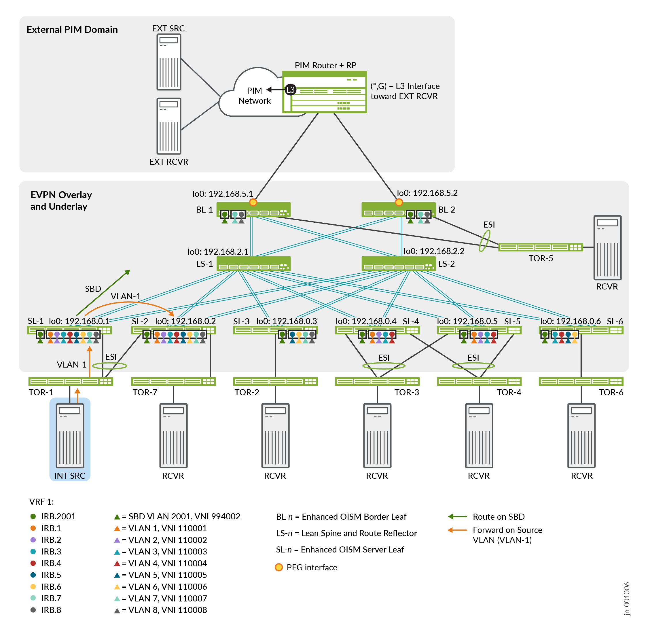
Table 2 describes the multicast groups, device roles, configured VLANs, VXLAN VNI mappings for the VLANs, and the corresponding IRB interfaces for each VLAN.

Table 2: Use Case #1 Elements for Internal Multicast Flow with Multihoming Peer and IGMPv3

Role

Device

Configured Revenue VLANs

Configured IRB Interfaces

VXLAN VNI Mappings

SBD for VRF-1 on all enhanced OISM leaf devices: VLAN-2001, irb.2001, VNI 994002

Multicast source VLAN: VLAN-1, Source Host IP address: 10.0.1.12

IGMPv3—SSM multicast groups: 233.252.0.1 – 233.252.0.3 for intra-VLAN (L2), and 233.252.0.101 – 233.252.0.103 for inter-VLAN (L3)

Source

TOR-1—Multihomed to SL-11 and SL-21

VLAN-1 - VLAN-8

irb.1 - irb.8

VNI 110001 - VNI 110008

Receivers

TOR-7—Single-homed to SL-21

VLAN-1 - VLAN-8

irb.1 - irb.8

VNI 110001 - VNI 110008

TOR-2—Single-homed to SL-3

VLAN-5- VLAN-8

irb.5- irb.8

VNI 110005- VNI 110008

TOR-3—Multihomed to SL-42 and SL-52

VLAN-1 - VLAN-4

irb.1 - irb.4

VNI 110001 - VNI 110004

TOR-4—Multihomed to SL-42 and SL-52

VLAN-1 - VLAN-4

irb.1 - irb.4

VNI 110001 - VNI 110004

TOR-5—Multihomed to BL-13 and BL-23

VLAN-7 - VLAN-8

irb.7 - irb.8

VNI 110007 - VNI 110008

TOR-6—Single-homed to SL-6

VLAN-3 - VLAN-6

irb.3 - irb.6

VNI 110003 - VNI 110006

1 SL-1 and SL-2 are multihoming peers, so we configure the same revenue VLANs on SL-1 and SL-2.

2 SL-4 and SL-5 are multihoming peers, so we configure the same revenue VLANs on SL-4 and SL-5.

3 BL-1 and BL-2 are multihoming peers, so we configure the same revenue VLANs on BL-1 and BL-2.

Configure Use Case #1: Internal Source and Receivers with Multihoming Peer Receiver and IGMPv3—SSM

Configure the revenue VLANs, SBD, tenant VRF, and multicast protocols specific to the use case in Use Case #1: Internal Source to Internal Receivers (Including Multihoming Peer) with IGMPv3—SSM.

  1. On each OISM leaf device, in the MACVRF-1 instance, configure the hosted revenue VLANs and their corresponding IRB interfaces and VNI mappings.

    SL-1 and SL-2 (multihoming peer devices)—VLANs 1 through 8:

    SL-3—VLANs 5 through 8:

    SL-4 and SL-5 (multihoming peer devices)—VLANs 1 through 4:

    SL-6—VLANs 3 through 6:

    BL-1 and BL-2 (multihoming peer devices)—VLANs 7 and 8:

  2. On all OISM leaf devices, in the MACVRF-1 instance in this use case, configure the SBD VLAN, corresponding IRB interface, and VNI mapping.
  3. On each device, configure the hosted revenue VLAN IRB interfaces and the SBD IRB interface in this use case as L3 gateways with IPv4 and IPv6 dual stack addresses.

    In this example, we configure the interfaces as gateways using a unique IRB IP address with a virtual gateway address (VGA).

    On SL-1 for irb.1 (corresponds to revenue VLAN 1), for example:

    Use the same configuration on each leaf device to configure the gateway settings for the IRB interfaces for the hosted revenue VLANs and the SBD lRB interface, but substitute the following values to use unique addresses per IRB interface and per leaf device:

    Note:

    The SBD IRB interface VGA is common to all of the leaf devices for the VRF in this use case.

    Table 3: Use Case #1 IRB Addresses and Virtual Gateway Addresses

    Leaf Device

    IRB Interface Unit#

    IRB IPv4 Address

    IPv4 VGA

    IRB IPv6 Address

    IPv6 VGA

    SL-1

    Revenue VLANs—1 through 8

    10.0.unit#.243/24

    10.0.unit#.254

    2001:db8::10:0:unit#:243/112

    2001:db8::10:0:unit#:254

    SBD—2001

    10.20.1.243/24

    10.20.1.254

    2001:db8::10:0:7d1:243/112

    2001:db8::10:0:7d1:254

    SL-2

    Revenue VLANs—1 through 8

    10.0.unit#.244/24

    10.0.unit#.254

    2001:db8::10:0:unit#:244/112

    2001:db8::10:0:unit#:254

    SBD—2001

    10.20.1.244/24

    10.20.1.254

    2001:db8::10:0:7d1:244/112

    2001:db8::10:0:7d1:254

    SL-3

    Revenue VLANs—5 through 8

    10.0.unit#.245/24

    10.0.unit#.254

    2001:db8::10:0:unit#:245/112

    2001:db8::10:0:unit#:254

    SBD—2001

    10.20.1.245/24

    10.20.1.254

    2001:db8::10:0:7d1:245/112

    2001:db8::10:0:7d1:254

    SL-4

    Revenue VLANs—1 through 4

    10.0.unit#.246/24

    10.0.unit#.254

    2001:db8::10:0:unit#:246/112

    2001:db8::10:0:unit#:254

    SBD—2001

    10.20.1.246/24

    10.20.1.254

    2001:db8::10:0:7d1:246/112

    2001:db8::10:0:7d1:254

    SL-5

    Revenue VLANs—1 through 4

    10.0.unit#.247/24

    10.0.unit#.254

    2001:db8::10:0:unit#:247/112

    2001:db8::10:0:unit#:254

    SBD—2001

    10.20.1.247/24

    10.20.1.254

    2001:db8::10:0:7d1:247/112

    2001:db8::10:0:7d1:254

    SL-6

    Revenue VLANs—3 through 6

    10.0.unit#.248/24

    10.0.unit#.254

    2001:db8::10:0:unit#:248/112

    2001:db8::10:0:unit#:254

    SBD—2001

    10.20.1.248/24

    10.20.1.254

    2001:db8::10:0:7d1:248/112

    2001:db8::10:0:7d1:254

    BL-1

    Revenue VLANs—7 and 8

    10.0.unit#.241/24

    10.0.unit#.254

    2001:db8::10:0:unit#:241/112

    2001:db8::10:0:unit#:254

    SBD—2001

    10.20.1.241/24

    10.20.1.254

    2001:db8::10:0:7d1:241/112

    2001:db8::10:0:7d1:254

    BL-2

    Revenue VLANs—7 and 8

    10.0.unit#.242/24

    10.0.unit#.254

    2001:db8::10:0:unit#:242/112

    2001:db8::10:0:unit#:254

    SBD—2001

    10.20.1.242/24

    10.20.1.254

    2001:db8::10:0:7d1:242/112

    2001:db8::10:0:7d1:254

  4. This use case tests IGMPv3 SSM flows, so on each OISM leaf device, enable IGMP with the version 3 option on the IRB interfaces for the revenue VLANs the device hosts, and for the SBD.

    All OISM leaf devices—SBD:

    SL-1 and SL-2 (multihoming peer devices)—irb.1 through irb.8:

    SL-3—irb.5 through irb.8:

    SL-4 and SL-5 (multihoming peer devices)—irb.1 through irb.4:

    SL-6—irb.3 through irb.6:

    BL-1 and BL-2 (multihoming peer devices)—irb.7 and irb.8:

  5. On each OISM leaf device, enable IGMP snooping for IGMP version 3 in the MACVRF-1 instance for the revenue VLANs the device hosts and the SBD.

    In EVPN-VXLAN fabrics, we support IGMPv2 traffic with ASM reports only. We support IGMPv3 traffic with SSM reports only. As a result, when you enable IGMP snooping for IGMPv3 traffic, you must include the SSM-specific evpn-ssm-reports-only configuration option. See Supported IGMP or MLD Versions and Group Membership Report Modes for more on ASM and SSM support with EVPN-VXLAN.

    All OISM leaf devices—SBD:

    SL-1 and SL-2—VLANs 1 through 8:

    SL-3—VLANs 5 through 8:

    SL-4 and SL-5—VLANs 1 through 4:

    SL-6—VLANs 3 through 6:

    BL-1 and BL-2—VLANs 7 and 8:

  6. On each OISM leaf device, configure a loopback logical interface for the VRF instance. We include this interface in the VRF instance, VRF-1, in the next step.

    For the loopback logical interface configuration, we use the following conventions:

    • The logical unit number matches the VRF instance number.

    • The last octet of the interface's IP address also matches the VRF instance number.

    SL-1:

    SL-2:

    SL-3:

    SL-4:

    SL-5:

    SL-6:

    BL-1:

    BL-2:

  7. Configure the tenant VRF instance named VRF-1 on each of the OISM leaf devices.

    VRF instance configuration with enhanced OISM is very similar to VRF instance configuration with regular OISM, except you include the revenue VLAN IRB interfaces corresponding only to the revenue VLANs the device hosts. You also include the following:

    • Identify the OISM SBD IRB interface associated with the VRF instance.

    • On the server leaf devices:

      • Configure an OSPF area with the SBD IRB interface in OSPF active mode. Include the OSPF priority 0 option with the SBD IRB interface so server leaf device SBD IRB interfaces never assume the designated router (DR) or backup designated router (BDR) role in the OSPF area. Configure OSPF passive mode for the remaining interfaces in the VRF instance so they can share routes internally without forming OSPF adjacencies.

      • Configure PIM in the VRF instance in passive mode on the interfaces for all hosted revenue VLANs and the SBD. Include the PIM accept-remote-source option so the SBD IRB interface accepts traffic arriving on that interface as the source interface.

      • Add the following interfaces to the VRF instance:

        • The SBD IRB interface for this VRF

        • The hosted revenue VLAN IRB interfaces

        • The loopback logical interface for this VRF (you configure the loopback logical interface in Step 6 above)

    • On the border leaf devices, which act as PEG devices to route multicast traffic from internal sources to external receivers, and from external sources to internal receivers:

      • Identify the border leaf device as a PEG device in the VRF instance using the pim-evpn-gateway option at the [edit routing-instances name protocols evpn oism] hierarchy level.

      • Configure an OSPF area for the VRF instance with an export policy to share OSPF learned routes, and includes the following interfaces:

        • The interface that connects to the external PIM domain, in OSPF active mode

          Note:

          The border leaf devices in this example use ae3 as L3 PEG interfaces to route traffic to and from the external PIM domain (see Figure 1). Each VRF instance uses a different logical unit on the ae3 interface for that purpose to configure multiple use cases in the same topology. In this use case, VRF-1 on the border leaf devices uses ae3.0 (logical unit = VRF instance number - 1).

        • The SBD IRB interface for the VRF instance (irb.2001 in this case), in OSPF active mode

        • The remaining interfaces in passive mode to share internal routes without forming OSPF adjacencies

      • Configure PIM in the VRF instance as follows:

        • Statically configure the address for the PIM rendezvous point (RP) in the external PIM domain.

          Note:

          In our test environment, we use an MX Series router as the PIM router and PIM RP in an external PIM domain. See Configure External Multicast PIM Router and PIM RP Router for more on how to configure an MX Series router as a PIM router and RP with regular OISM; the steps are similar with enhanced OISM.

        • Set distributed-dr mode on the IRB interfaces for the revenue VLANs.

        • Enable PIM in regular mode on the interface that connects to the external PIM domain and the loopback logical interface for the VRF instance.

        • Enable PIM in regular mode on the SBD IRB interface, with the following options:

          • Bidirectional Forwarding Detection (BFD) to improve convergence time with interface issues to help avoid traffic loss.

          • The stickydr option to avoid designated router switchover convergence delays during reboot events.

          • The accept-remote-source option to enable the SBD IRB interface to accept traffic arriving on that interface as the source interface.

        • (QFX Series switches) Set the PIM disable-packet-register option for the VRF instance. The border leaf devices are the first-hop routers (FHRs) toward the external multicast PIM domain router and RP. However, for the PIM source registration process, QFX Series switches don't encapsulate (or decapsulate) multicast packets in PIM register messages and don't generate the PIM register stop message. Without a PIM register stop message, the source registration process doesn't terminate properly. As a result, to avoid keeping the PIM registration process in an unpredictable state, we use this option on the border leaf devices that are QFX Series switches.

      • Add the following interfaces to the VRF instance:

        • The interface that connects to the external PIM domain—ae3.0

        • The SBD IRB interface for this VRF

        • The hosted revenue VLAN IRB interfaces

        • The loopback logical interface for this VRF

    Our enhanced OISM configuration also uses the following conventions in VRF instance configurations on all OISM leaf devices:

    • Enable the graceful restart feature to help with OISM traffic convergence after failure events.

    • Use a route target that's the same for this VRF instance on all of the leaf devices, in which the last segment of the value matches the number in the VRF instance name.

    • Use a route distinguisher (RD) for this VRF instance on each leaf device, in which the first part of the RD value mirrors the device loopback (unit 0) IP address, and the second part matches the VRF instance number.

    All server leaf devices SL-1 through SL-6:

    Border leaf devices BL-1 and BL-2:

    Then in the VRF instance configuration on each of the leaf devices, add the IRB interfaces only for the revenue VLANs the device hosts:

    SL-1 and SL-2—irb.1 through irb.8

    SL-3—irb.5 through irb.8:

    SL-4 and SL-5—irb.1 through irb.4:

    SL-6—irb.3 through irb.6:

    BL-1 and BL-2—irb.7 and irb.8:

Verify Use Case#1: Internal Source and Receivers with Multihoming Peer Receiver and IGMPv3—SSM

Verify enhanced OISM operation for use case #1, in which the internal source is behind SL-1 and SL-2. SL-2 is a multihoming peer of SL-1, and also has an internal receiver. SL-3 through SL-6, BL-1, and BL-2 also have internal receivers. See the topology in Figure 2, and the configuration in Configure Use Case #1: Internal Source and Receivers with Multihoming Peer Receiver and IGMPv3—SSM.

  1. Run the show vlans command for the revenue VLANs on each leaf device to see the VXLAN tunnel end points (VTEPs) between the leaf devices.
    With the enhanced OISM asymmetric bridge domains model, each leaf device only needs to maintain VTEPs to the other leaf devices for the VLANs they host in common.

    For example, on SL-1, you see the following:

    • For VLAN-1—3 VTEPs for the leaf devices that host VLAN-1 (SL-2, SL-4, and SL-5)

    • For VLAN-2—3 VTEPs for the leaf devices that host VLAN-2 (SL-2, SL-4, and SL-5)

    • For VLAN-3—4 VTEPs for the leaf devices that host VLAN-3 (SL-2, SL-4, SL-5, and SL-6)

    • For VLAN-4—4 VTEPs for the leaf devices that host VLAN-4 (SL-2, SL-4, SL-5, and SL-6)

    • For VLAN-5—3 VTEPs for the leaf devices that host VLAN-5 (SL-2, SL-3, and SL-6)

    • For VLAN-6—3 VTEPs for the leaf devices that host VLAN-6 (SL-2, SL-3, and SL-6)

    • For VLAN-7—4 VTEPs for the leaf devices that host VLAN-7 (SL-2, SL-3, BL-1, and BL-2)

    • For VLAN-8—4 VTEPs for the leaf devices that host VLAN-8 (SL-2, SL-3, BL-1, and BL-2)

    On the other devices, you see output only for the VLANs those devices host, with the corresponding VTEPs to the other leaf devices that host the same VLANs.

    SL-1 (output is similar on SL-2, which is a multihoming peer of SL-1):

    SL-3 (output is similar on SL-6 for the revenue VLANs SL-6 hosts):

    SL-5 (output is similar on SL-4, which is a multihoming peer of SL-5):

  2. Run the show vlans command for the SBD (VLAN-2001) on each leaf device to see the SBD VTEPs between the leaf devices.

    You should see VTEPs to each of the other leaf devices (seven VTEPs in this case). We show output only for SL-2; the results should be similar on all of the leaf devices.

    SL-2:

  3. Run the show interfaces irb.unit# terse command on each of the leaf devices to verify the revenue VLAN IRB interfaces are up, and the SBD IRB interface is up.

    SL-2 (output is similar on SL-1):

    SL-3 (output is similar on SL-6 for the revenue VLANs and IRB interfaces you configure on SL-6):

    SL-5 (output is similar on SL-4):

  4. Run the show pim join extensive instance VRF-1 command on the leaf devices to see the joined multicast groups, source address, upstream neighbors, and downstream neighbors. These values show enhanced OISM in action. For more details on how enhanced OISM east-west traffic flow works, see How Enhanced OISM Works.

    For example, we show output from this command for this use case on SL-2 as a source leaf device, and SL-3 and SL-5 as receiving leaf devices. Based on the test environment for this use case (see Table 2), note the following in the output:

    • Group—We use multicast groups 233.252.0.1 through 233.252.0.3 for intra-VLAN traffic (L2 forwarding), and 233.252.0.101 through 233.252.0.103 for inter-VLAN (L3 routing) traffic.

    • Source—The IGMPv3 SSM multicast source is behind multihoming peer leaf devices SL-1 and SL-2, with source address 10.0.1.12.

    • Upstream Interface, Downstream neighbors—The source VLAN is VLAN-1 with corresponding IRB interface irb.1 (the upstream interface). The output shows that with enhanced OISM, either SL-1 or SL-2 send the source traffic toward the receivers from the source VLAN out onto the SBD (irb.2001 is the downstream neighbor) instead of on the source VLAN the way regular OISM operates.

      Also, with enhanced OISM, the leaf devices that host receivers, such as SL-3, SL-4, and SL-5 shown below, receive the traffic on the SBD (irb.2001 is the upstream neighbor), whether the traffic is intra-VLAN or inter-VLAN. Then those leaf devices route the traffic from the SBD to the destination VLAN using the corresponding IRB interfaces. The output is similar for the receivers behind the other leaf devices based on the VLANs they host.

    SL-2 in the source role (output is similar on SL-1):

    SL-3 in the receiver role (SL-3 hosts VLANs 5 through 8):

    SL-5 in the receiver role (SL-5 hosts VLANs 1 through 4; output is similar for multihoming peer device SL-4):

  5. Run the show multicast route source-prefix 10.0.1.12 instance VRF-1 extensive command on the leaf devices to check for the expected routes in the multicast routing table.

    For example, we include the output for this use case on SL-2 as a source leaf device, and SL-3 and SL-5 as receiving leaf devices.

    Like in Step 4 of this verification, the output on SL-1 and SL-2 (source devices) should show that SL-1 and SL-2:

    • Receive the traffic on source VLAN 1 (irb.1) as the upstream interface.

    • Route the traffic out onto the SBD (irb.2001) toward the receivers for either intra-VLAN (L2) or inter-vlan (L3) multicast flows.

    The output on SL-3 and SL-5 should show that SL-3 and SL-5:

    • Receive the traffic on the SBD as the upstream interface.

    • Route the traffic to the destination VLAN for the VLANs they host.

    SL-2 in the source role (output is similar on SL-1):

    SL-3 in the receiver role (SL-3 hosts VLANs 5 through 8):

    SL-5 in the receiver role (SL-5 hosts VLANs 1 through 4; output is similar for multihoming peer device SL-4):

  6. Verify that multihoming peer devices receive source traffic on the source VLAN rather than on the SBD.

    In use case #1, SL-1 and SL-2 are multihoming peer devices with the multicast source behind them. On SL-2, we add a single-homed receiver connected on interface ae5 to TOR-7. See Figure 1. In this case, if SL-1 is the ingress leaf device and receives the source traffic, then with enhanced OISM, SL-1 sends the traffic to SL-2 on the source VLAN instead of on the SBD. SL-1 sends the source traffic on the SBD to the other leaf devices with interested receivers.

    For more details on how enhanced OISM east-west traffic flow works, see How Enhanced OISM Works.

    Run these commands on SL-2 with the single-homed receiver behind TOR-7:

    1. Run the show igmp snooping membership command for the EVPN instance MACVRF-1 to verify that IGMP snooping is enabled on the VLANs that SL-2 hosts. You can also verify the multicast groups the receiver behind TOR-7 has joined. We show output for the first few VLANs. The output is similar for the remaining VLANs.
    2. Run the show pim join extensive instance VRF-1 command to verify the upstream interface is the IRB interface for the source VLAN, which is irb.1 in this case. The downstream neighbors include the SBD IRB interface and the other revenue VLAN IRB interfaces that have local receivers on the corresponding VLAN.
    3. Run the show multicast route source-prefix 10.0.1.12 instance VRF-1 command to check for the expected routes in the multicast forwarding table. The the source VLAN IRB interface, irb.1, is the upstream interface. The outgoing interface list (the downstream interface list) consists of the other IRB interfaces to which the device forwards and routes the multicast traffic.
    4. Run the show multicast snooping route source-prefix 10.0.1.12 instance MACVRF-1 extensive command to check for the expected entries in the multicast snooping forwarding table with the outgoing interface for the multicast traffic. (For brevity, in the output below we have trimmed similar results for some of the multicast groups.)

Use Case #2: Internal Source to Internal and External Receivers with IGMPv2—ASM

In use case #2, we configure the topology in Figure 3 with a tenant VRF called VRF-26. This use case includes:

  • Intra-VLAN and inter-VLAN multicast flows using IGMPv2.

  • A single-homed internal multicast source and internal multicast receivers.

  • An external multicast receiver in an external PIM domain. As a result:

    • The ingress leaf device advertises EVPN Type 10 S-PMSI A-D routes for each internal multicast source and group (S,G).

    • The OISM border leaf PEG devices, BL-1 and BL-2, receive the EVPN Type 10 route. The BL device that is the PIM designated router (DR) for the SBD, BL-2 in this case, sends a PIM register message for the (S,G) on its PEG interface to the PIM router in the external PIM domain.

    • In response to the PIM register message, the PIM router sends a PIM Join message to either of the multihomed attached OISM PEG devices, BL-1 or BL-2. In this case, BL-2 receives the PIM Join message. .

    • The OISM PEG device that receives the PIM join, BL-2, sends the multicast traffic on its PEG interface toward the external receiver behind the PIM router.

    Note:

    The test environment uses an MX Series router as the PIM router and PIM RP in an external PIM domain. See Configure External Multicast PIM Router and PIM RP Router for an example of how to configure an MX Series router as a PIM router and RP with regular OISM; the steps are similar with enhanced OISM.

Figure 3: Enhanced OISM Use Case #2 Topology—IGMPv2 with Source Behind SL-3 and External Receiver in External PIM Domain Enhanced OISM Use Case #2 Topology—IGMPv2 with Source Behind SL-3 and External Receiver in External PIM Domain

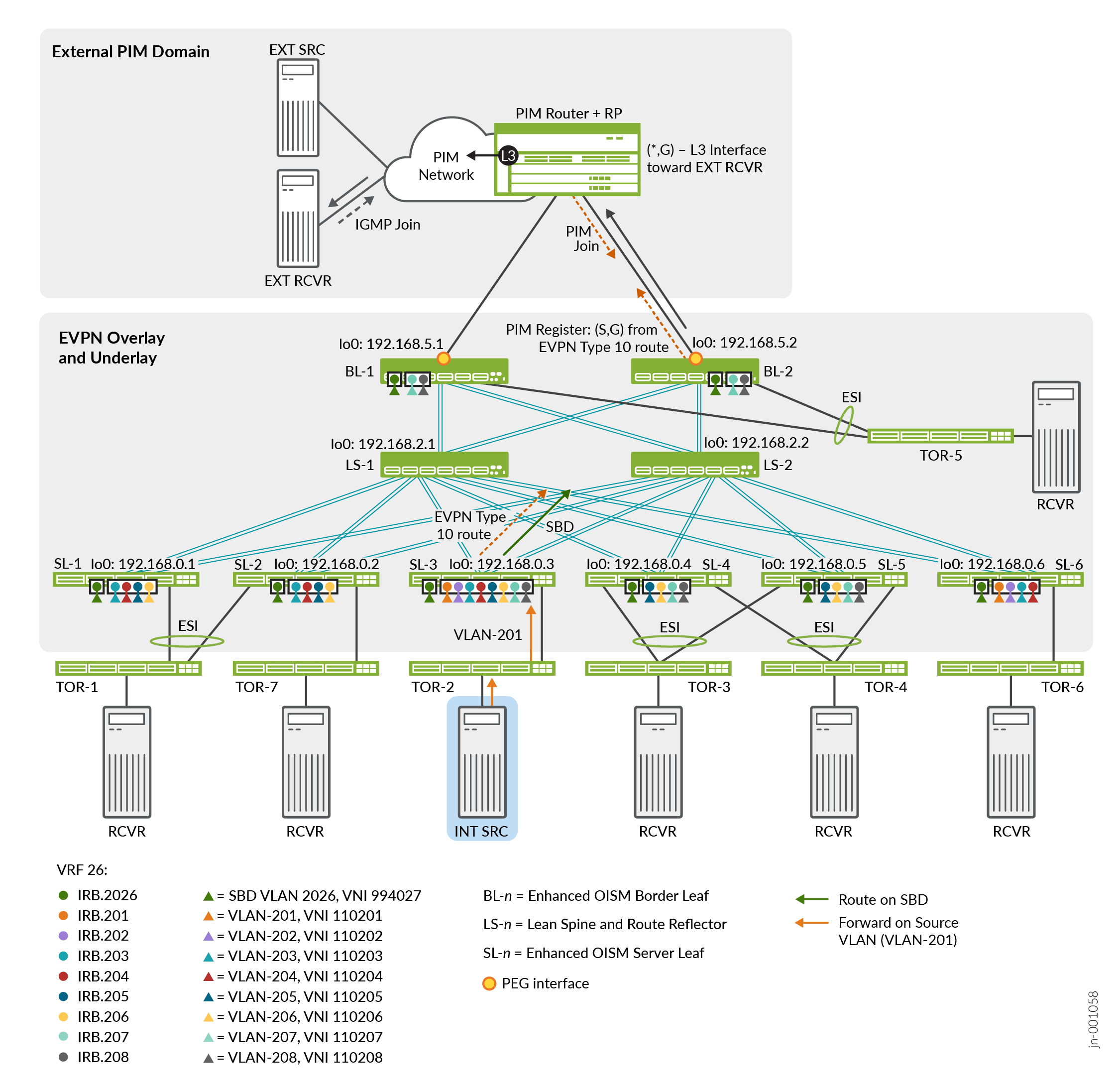
Table 4 describes the multicast groups, device roles, configured VLANs, VXLAN VNI mappings for the VLANs, and the corresponding IRB interfaces for each VLAN.

Table 4: Use Case#2 Elements for Internal Source to Internal and External Receivers with IGMPv2

Role

Device

Configured Revenue VLANs

Configured IRB Interfaces

VXLAN VNI Mappings

SBD for VRF-26 on all enhanced OISM leaf devices: VLAN-2026, irb.2026, VNI 994027

Multicast source VLAN: VLAN-201, Source Host IP address: 10.0.201.12

IGMPv2—ASM multicast groups: 233.252.0.71 – 233.252.0.73 for intra-VLAN (L2), and 233.252.0.171 – 233.252.0.173 for inter-VLAN (L3)

Source

TOR-2—Single-homed to SL-3

VLAN-201 - VLAN-208

irb.201 - irb.208

VNI 110201 - VNI 110208

Receivers

TOR-1—Multihomed to SL-11 and SL-21

VLAN-203- VLAN-206

irb.203- irb.206

VNI 110203- VNI 110206

TOR-3—Multihomed to SL-42 and SL-52

VLAN-205 - VLAN-208

irb.205 - irb.208

VNI 110205 - VNI 110208

TOR-4—Multihomed to SL-42 and SL-52

VLAN-205 - VLAN-208

irb.205 - irb.208

VNI 110205 - VNI 110208

TOR-5—Multihomed to BL-13 and BL-23

VLAN-207 - VLAN-208

irb.207 - irb.208

VNI 110207 - VNI 110208

TOR-6—Single-homed to SL-6

VLAN-201 - VLAN-204

irb.201 - irb.204

VNI 110201 - VNI 110204

EXT RCVR in External PIM domain

VLAN-3126

n/a

n/a

1 SL-1 and SL-2 are multihoming peers, so configure the same revenue VLANs on SL-1 and SL-2.

2 SL-4 and SL-5 are multihoming peers, so configure the same revenue VLANs on SL-4 and SL-5.

3 BL-1 and BL-2 are multihoming peers, so configure the same revenue VLANs on BL-1 and BL-2.

Configure Use Case #2: Internal Source to Internal and External Receivers with IGMPv2—ASM

Configure the revenue VLANs, SBD, tenant VRF, and multicast protocols specific to the use case in Use Case #2: Internal Source to Internal and External Receivers with IGMPv2—ASM.

The main differences in this use case from use case #1 are that here:

  • We use enhanced OISM for multicast flows with IGMPv2 (ASM) from a single-homed source behind SL-3.

  • SL-3 hosts revenue VLANs VLAN-201 through VLAN-208, and the other leaf devices host different subsets of those revenue VLANs.

  • We use VRF-26, and configure the SBD for this VRF as VLAN-2026.

  1. On each OISM leaf device, configure the revenue VLANs the device hosts, their corresponding IRB interfaces, and VNI mappings in the same way as Configure Use Case #1: Internal Source and Receivers with Multihoming Peer Receiver and IGMPv3—SSM for steps 1 through 3, but use the values in Table 4, and Table 5 below for the IRB interface addresses and virtual gateway addresses.
    Table 5: Use Case #2 IRB Addresses and Virtual Gateway Addresses

    Leaf Device

    IRB Interface Unit#

    IRB IPv4 Address

    IPv4 VGA

    IRB IPv6 Address

    IPv6 VGA

    SL-1

    Revenue VLANs—201 through 208

    10.0.unit#.243/24

    10.0.unit#.254

    2001:db8::10:0:hex-unit#:243/112

    2001:db8::10:0:hex-unit#:254

    SBD—2026

    10.20.26.243/24

    10.20.26.254

    2001:db8::10:0:7ea:243/112

    2001:db8::10:0:7ea:254

    SL-2

    Revenue VLANs—201 through 208

    10.0.unit#.244/24

    10.0.unit#.254

    2001:db8::10:0:hex-unit#:244/112

    2001:db8::10:0:hex-unit#:254

    SBD—2026

    10.20.26.244/24

    10.20.26.254

    2001:db8::10:0:7ea:244/112

    2001:db8::10:0:7ea:254

    SL-3

    Revenue VLANs—205 through 208

    10.0.unit#.245/24

    10.0.unit#.254

    2001:db8::10:0:hex-unit#:245/112

    2001:db8::10:0:hex-unit#:254

    SBD—2026

    10.20.26.245/24

    10.20.26.254

    2001:db8::10:0:7ea:245/112

    2001:db8::10:0:7ea:254

    SL-4

    Revenue VLANs—201 through 204

    10.0.unit#.246/24

    10.0.unit#.254

    2001:db8::10:0:hex-unit#:246/112

    2001:db8::10:0:hex-unit#:254

    SBD—2026

    10.20.26.246/24

    10.20.26.254

    2001:db8::10:0:7ea:246/112

    2001:db8::10:0:7ea:254

    SL-5

    Revenue VLANs—201 through 204

    10.0.unit#.247/24

    10.0.unit#.254

    2001:db8::10:0:hex-unit#:247/112

    2001:db8::10:0:hex-unit#:254

    SBD—2026

    10.20.26.247/24

    10.20.26.254

    2001:db8::10:0:7ea:247/112

    2001:db8::10:0:7ea:254

    SL-6

    Revenue VLANs—203 through 206

    10.0.unit#.248/24

    10.0.unit#.254

    2001:db8::10:0:hex-unit#:248/112

    2001:db8::10:0:hex-unit#:254

    SBD—2026

    10.20.26.248/24

    10.20.26.254

    2001:db8::10:0:7ea:248/112

    2001:db8::10:0:7ea:254

    BL-1

    Revenue VLANs—207 and 208

    10.0.unit#.241/24

    10.0.unit#.254

    2001:db8::10:0:hex-unit#:241/112

    2001:db8::10:0:hex-unit#:254

    SBD—2026

    10.20.26.241/24

    10.20.26.254

    2001:db8::10:0:7ea:241/112

    2001:db8::10:0:7ea:254

    BL-2

    Revenue VLANs—207 and 208

    10.0.unit#.242/24

    10.0.unit#.254

    2001:db8::10:0:hex-unit#:242/112

    2001:db8::10:0:hex-unit#:254

    SBD—2026

    10.20.26.242/24

    10.20.26.254

    2001:db8::10:0:7ea:242/112

    2001:db8::10:0:7ea:254

  2. This use case tests IGMPv2 ASM flows. IGMPv2 is enabled by default on all interfaces on which you configure PIM, so you don't need to explicitly enable IGMP in this case. Each OISM leaf device will use IGMPv2 on the IRB interfaces for which you did not explicitly configure IGMPv3 with the [edit protocols igmp interface interface-name version 3 statement.
  3. On each OISM leaf device, enable IGMP snooping for IGMPv2 in the MACVRF-1 instance for the revenue VLANs the device hosts, and the SBD.

    For simplicity, you can enable IGMP snooping for all VLANs in the MAC-VRF instance with the following command:

    Note:

    With the vlan all option above, if you need IGMP snooping with IGMPv3 for some of the VLANs, you can explicitly enable IGMP snooping with the evpn-ssm-reports-only option only for those VLANs, as we do in use case #1. The remaining VLANs will use IGMP snooping with IGMPv2.

    Alternatively, on each device you can enable IGMP snooping explicitly for the SBD and the VLANs that device hosts.

    All OISM leaf devices:

    SL-1 and SL-2—VLANs 203 through 206:

    SL-3—VLANs 201 through 208:

    SL-4 and SL-5—VLANs 205 through 208:

    SL-6—VLANs 201 through 204:

    BL-1 and BL-2—VLANs 207 and 208:

  4. On each OISM leaf device, configure a loopback logical interface for the VRF instance. We include this interface in the VRF instance, VRF-26, in the next step.

    For the loopback logical interface configuration, we use the following conventions:

    • The logical unit number matches the VRF instance number.

    • The last octet of the interface's IP address also matches the VRF instance number.

    SL-1:

    SL-2:

    SL-3:

    SL-4:

    SL-5:

    SL-6:

    BL-1:

    BL-2:

  5. Configure the tenant VRF instance named VRF-26 on each of the OISM leaf devices.

    Include the same elements for the server leaf and border leaf devices in the VRF configuration as we describe in use case #1, Step 7, with the following differences for this use case:

    • Identify the OISM SBD IRB interface associated with this VRF instance, which is irb.26.

    • On the border leaf devices, the L3 PEG interface for VRF-26 is ae3.25 (logical unit = VRF instance number - 1).

    • On each device, include the loopback logical interface for this VRF instance that you configure in Step 4 above.

    • Use the same route target for this VRF instance on all of the OISM leaf devices—target:100:26.

    • Configure an RD following the same convention as in use case #1, in which the first part of the RD value mirrors the device loopback (unit 0) IP address, and the second part matches the VRF instance number—device-loopback-unit-0-address:26.

    All server leaf devices SL-1 through SL-6:

    Border leaf devices BL-1 and BL-2:

    Then in the VRF instance configuration on each of the leaf devices, add the IRB interfaces only for the revenue VLANs the device hosts:

    SL-1 and SL-2:

    SL-3:

    SL-4 and SL-5:

    SL-6:

    BL-1 and BL-2:

Verify Use Case #2: Internal Source to Internal and External Receivers with IGMPv2—ASM

Verify enhanced OISM operation for use case #2 where we have a single-homed internal source behind SL-3 sending IGMPv2 multicast traffic. SL-2 is a multihoming peer of SL-1, and also connects to an internal receiver on TOR-7. SL-3 through SL-6, BL-1, and BL-2 connect to internal receivers. An external receiver also subscribes to the source traffic through an external PIM router and RP by way of OISM PEG devices BL-1 and BL-2. See the topology in Figure 3, and the configuration in Configure Use Case #2: Internal Source to Internal and External Receivers with IGMPv2—ASM.

In this case, we focus on how to verify enhanced OISM operation with an external receiver. SL-6, as the ingress OISM leaf device, advertises EVPN Type 10 S-PMSI A-D routes for the multicast source and groups (S,G). BL-1 and BL-2 receive the EVPN Type 10 route on the SBD. In this example, BL-2 is the PIM DR for the SBD, so BL-2 sends a PIM register message for the (S,G) on its PEG interface to the PIM router and RP. The PIM router sends a PIM Join back to either of the multihomed attached OISM PEG devices, in this case BL-2. BL-2 sends multicast traffic from that (S,G) on its PEG interface toward the external receiver.

See Use Case #2: Internal Source to Internal and External Receivers with IGMPv2—ASM for all of the parameters in this use case.

  1. Run the show pim join extensive instance VRF-26 command on SL-3, the ingress leaf device, to see the joined multicast groups, source address, upstream neighbors, and downstream neighbors. For more details on how enhanced OISM north-south traffic flow works, see How Enhanced OISM Works.

    Note the following in the output:

    • Group—Multicast groups 233.252.0.71 through 233.252.0.73 for intra-VLAN traffic (L2 forwarding), and 233.252.0.171 through 233.252.0.173 for inter-VLAN (L3 routing) traffic.

    • Source—The multicast source behind SL-3 has source address 10.0.201.12.

    • Upstream Interface, Downstream neighbors—The source VLAN is VLAN-201. SL-3 receives the traffic on irb.201 (the upstream interface). With enhanced OISM, SL-3 routes the multicast traffic to the other leaf devices only on the SBD, and the receiving leaf devices all receive the traffic on the SBD. As a result, the upstream interface would be irb.2026, the SBD IRB interface, for the receiving devices. Between the multihoming peer receiver devices BL-1 and BL-2, BL-2 received the PIM Join in this case, so BL-2 routes the traffic from the SBD toward the external receiver on its PEG interface.

    SL-3 in the source role for the first multicast group (output is similar for the other groups):

  2. Use the show evpn oism spmsi-ad command to see the source and group (S,G) information in the EVPN Type 10 S-PMSI A-D routes that SL-3 advertises and BL-2 receives.

    For example, we show the output of this command for the source address in this use case (10.0.201.12) and the first intra-VLAN multicast group (233.252.0.71). The command and output are similar for the other multicast groups in this use case.

    SL-3:

    BL-2:

  3. Run the show route table MACVRF-1.evpn.0 match-prefix 10* extensive command to see the details about the EVPN Type 10 routes advertised by SL-3, the device that hosts the multicast source.

    For example, we show the EVPN Type 10 route table entries on SL-3 (the source device), BL-2 (a receiver and PEG device), and SL-2 (another receiver). We include results for the first multicast group in this use case, 233.252.0.71. The commands and output are similar for the other leaf devices and multicast groups in this use case.

    SL-3 in the source device role:

    SL-2 in the receiving device role:

    BL-2 in the receiving device role and as a PEG device:

Use Case #3: Internal Source to Internal Receivers with MLDv2—SSM

In use case #3, we configure the topology in Figure 4 with a tenant VRF called VRF-56. This use case includes:

  • An internal multicast source and internal multicast receivers.

  • Inter-VLAN IPv6 multicast flows using MLDv2 (none of the OISM leaf devices host the source VLAN, so all OISM traffic will be inter-VLAN traffic)

Note that we support both IPv4 and IPv6 multicast data traffic with an IPv4 EVPN core. We use the same underlay and overlay peering for MLD multicast traffic as we use for IGMP in use case #1 and use case #2.

Figure 4: Enhanced OISM Use Case #3 Topology—MLDv2 IPv6 Multicast with Internal Source Behind SL-6 and Internal Receivers Enhanced OISM Use Case #3 Topology—MLDv2 IPv6 Multicast with Internal Source Behind SL-6 and Internal Receivers

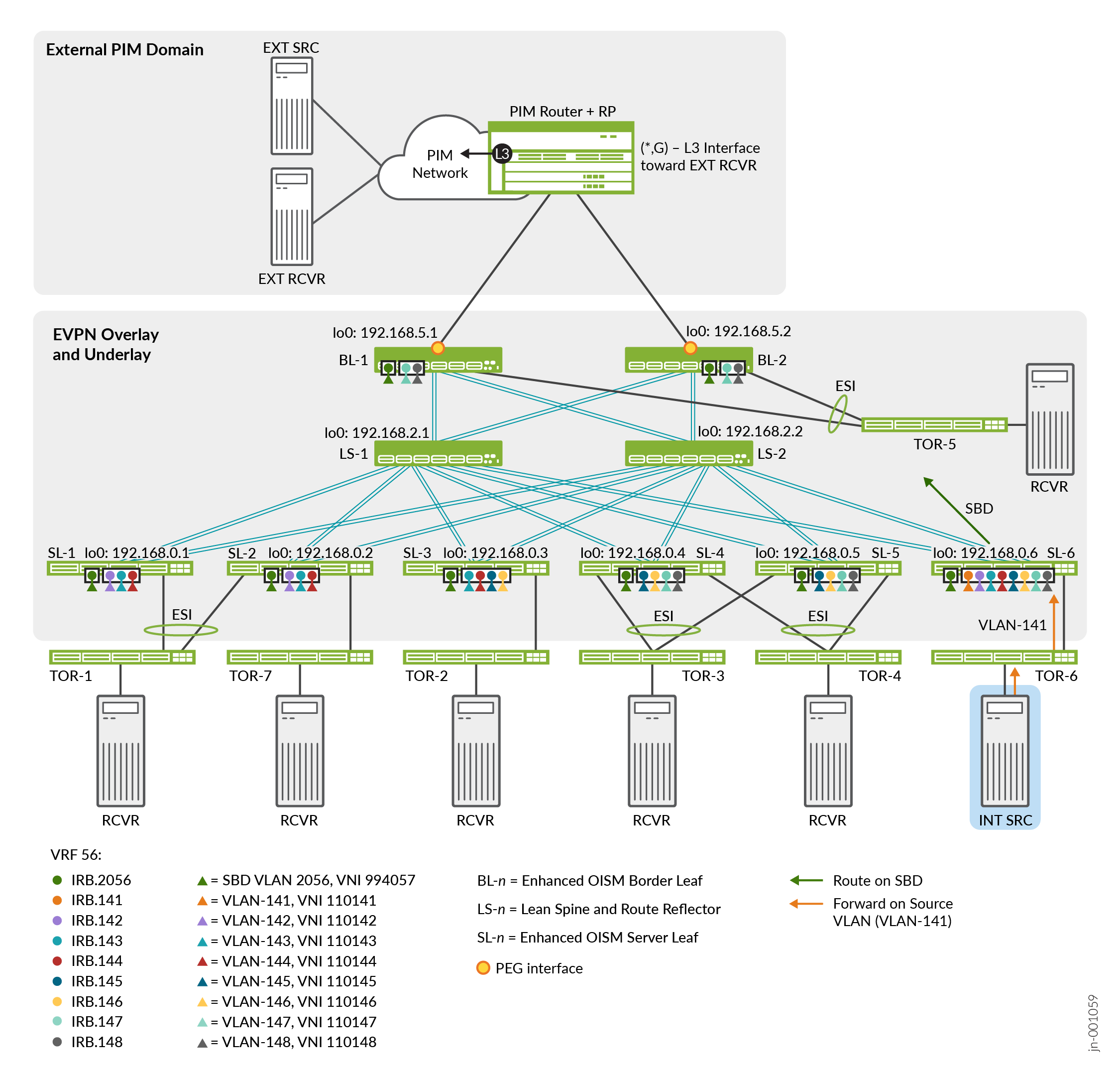
Table 6 describes the multicast groups, device roles, configured VLANs, VXLAN VNI mappings for the VLANs, and the corresponding IRB interfaces for each VLAN.

Table 6: Use Case #3 Elements for Internal Source to Internal Receivers with MLDv2

Role

Device

Configured Revenue VLANs

Configured IRB Interfaces

VXLAN VNI Mappings

SBD for VRF-56 on all enhanced OISM leaf devices: VLAN-2056, irb.2056, VNI 994057

Multicast source VLAN: VLAN-141, Source Host IPv6 address: 2001:db8::10:0:8d:0c

MLDv2—SSM multicast groups for inter-VLAN traffic only: ff0e::db8:0:1 – ff0e::db8:0:3 for inter-VLAN (L3)

Source

TOR-6—Single-homed to SL-6

VLAN-141 - VLAN-148

irb.141 - irb.148

VNI 110141 - VNI 110148

Receivers

TOR-1—Multihomed to SL-11 and SL-21

VLAN-142 - VLAN-144

irb.142 - irb.144

VNI 110142 - VNI 110144

TOR-7—Single-homed to SL-21

VLAN-142 - VLAN-144

irb.142 - irb.144

VNI 110142 - VNI 110144

TOR-2—Single-homed to SL-3

VLAN-143- VLAN-146

irb.143- irb.146

VNI 110143- VNI 110146

TOR-3—Multihomed to SL-42 and SL-52

VLAN-145 - VLAN-148

irb.145 - irb.148

VNI 110145 - VNI 110148

TOR-4—Multihomed to SL-42 and SL-52

VLAN-145 - VLAN-148

irb.145 - irb.148

VNI 110145 - VNI 110148

TOR-5—Multihomed to BL-13 and BL-23

VLAN-147 - VLAN-148

irb.147 - irb.148

VNI 110147 - VNI 110148

1 SL-1 and SL-2 are multihoming peers, so configure the same revenue VLANs on SL-1 and SL-2.

2 SL-4 and SL-5 are multihoming peers, so configure the same revenue VLANs on SL-4 and SL-5.

3 BL-1 and BL-2 are multihoming peers, so configure the same revenue VLANs on BL-1 and BL-2.

Configure Use Case #3: Internal Source and Receivers with MLDv2—SSM

Configure the revenue VLANs, SBD, tenant VRF, and multicast protocols specific to the use case in Use Case #3: Internal Source to Internal Receivers with MLDv2—SSM.

The main differences in this use case from use case #1 are that here:

  • We use enhanced OISM for IPv6 multicast flows with MLDv2 from a single-homed source behind SL-6.

  • SL-6 hosts revenue VLANs VLAN-141 through VLAN-148, and the other leaf devices host different subsets of revenue VLANs VLAN-142 through VLAN-148.

  • We configure a VRF named VRF-56, and configure the SBD for this VRF using VLAN-2056.

  1. On each OISM leaf device, configure the revenue VLANs the device hosts, their corresponding IRB interfaces, and VNI mappings in the same way as Configure Use Case #1: Internal Source and Receivers with Multihoming Peer Receiver and IGMPv3—SSM for steps 1 through 3, but use the values in Table 6, and refer to Table 7 below for the IRB interface addresses and virtual gateway addresses.
    Table 7: Use Case #3 IRB Addresses and Virtual Gateway Addresses

    Leaf Device

    IRB Interface Unit#

    IRB IPv4 Address

    IPv4 VGA

    IRB IPv6 Address

    IPv6 VGA

    SL-1

    Revenue VLANs—142 through 144

    10.0.unit#.243/24

    10.0.unit#.254

    2001:db8::10:0:hex-unit#:243/112

    2001:db8::10:0:hex-unit#:254

    SBD—2056

    10.20.56.243/24

    10.20.56.254

    2001:db8::10:0:808:243/112

    2001:db8::10:0:808:254

    SL-2

    Revenue VLANs—142 through 144

    10.0.unit#.244/24

    10.0.unit#.254

    2001:db8::10:0:hex-unit#:244/112

    2001:db8::10:0:hex-unit#:254

    SBD—2056

    10.20.56.244/24

    10.20.56.254

    2001:db8::10:0:808:244/112

    2001:db8::10:0:808:254

    SL-3

    Revenue VLANs—143 through 146

    10.0.unit#.245/24

    10.0.unit#.254

    2001:db8::10:0:hex-unit#:245/112

    2001:db8::10:0:hex-unit#:254

    SBD—2056

    10.20.56.245/24

    10.20.56.254

    2001:db8::10:0:808:245/112

    2001:db8::10:0:808:254

    SL-4

    Revenue VLANs—145 through 148

    10.0.unit#.246/24

    10.0.unit#.254

    2001:db8::10:0:hex-unit#:246/112

    2001:db8::10:0:hex-unit#:254

    SBD—2056

    10.20.56.246/24

    10.20.56.254

    2001:db8::10:0:808:246/112

    2001:db8::10:0:808:254

    SL-5

    Revenue VLANs—145 through 148

    10.0.unit#.247/24

    10.0.unit#.254

    2001:db8::10:0:hex-unit#:247/112

    2001:db8::10:0:hex-unit#:254

    SBD—2056

    10.20.56.247/24

    10.20.56.254

    2001:db8::10:0:808:247/112

    2001:db8::10:0:808:254

    SL-6

    Revenue VLANs—141 through 148

    10.0.unit#.248/24

    10.0.unit#.254

    2001:db8::10:0:hex-unit#:248/112

    2001:db8::10:0:hex-unit#:254

    SBD—2056

    10.20.56.248/24

    10.20.56.254

    2001:db8::10:0:808:248/112

    2001:db8::10:0:808:254

    BL-1

    Revenue VLANs—147 and 148

    10.0.unit#.241/24

    10.0.unit#.254

    2001:db8::10:0:hex-unit#:241/112

    2001:db8::10:0:hex-unit#:254

    SBD—2056

    10.20.56.241/24

    10.20.56.254

    2001:db8::10:0:808:241/112

    2001:db8::10:0:808:254

    BL-2

    Revenue VLANs—147 and 148

    10.0.unit#.242/24

    10.0.unit#.254

    2001:db8::10:0:hex-unit#:242/112

    2001:db8::10:0:hex-unit#:254

    SBD—2056

    10.20.56.242/24

    10.20.56.254

    2001:db8::10:0:808:242/112

    2001:db8::10:0:808:254

  2. This use case tests MLDv2 SSM flows, so enable MLD version 2 on the IRB interfaces for the revenue VLANs and the SBD in this use case.

    All OISM leaf devices—SBD:

    SL-1 and SL-2 (multihoming peer devices)—irb.142 through irb.144:

    SL-3—irb.143 through irb.146:

    SL-4 and SL-5 (multihoming peer devices)—irb.145 through irb.148:

    SL-6—irb.141 through irb.148:

    BL-1 and BL-2 (multihoming peer devices)—irb.147 and irb.148:

  3. IGMP snooping is enabled by default on the OISM leaf devices. So on each OISM leaf device, disable IGMP snooping and enable MLD snooping for MLDv2 in the MACVRF-1 instance for the SBD and the revenue VLANs the device hosts.

    In EVPN-VXLAN fabrics, we support MLDv1 traffic with ASM reports only. We support MLDv2 traffic with SSM reports only. As a result, when you enable MLD snooping for MLDv2 traffic, you must include the SSM-specific evpn-ssm-reports-only configuration option. See Supported IGMP or MLD Versions and Group Membership Report Modes for more on ASM and SSM support with EVPN-VXLAN.

    All OISM leaf devices—SBD:

    SL-1 and SL-2—VLANs 142 through 144:

    SL-3—VLANs 143 through 146:

    SL-4 and SL-5—VLANs 145 through 148:

    SL-6—VLANs 141 through 148:

    BL-1 and BL-2—VLANs 147 and 148:

    Note:

    MLDv1 is the default version when you enable MLD and MLD snooping. If you have a use case with MLDv1—ASM flows, you configure MLD without the version option, and configure MLD snooping without the evpn-ssm-reports-only option, as follows:

  4. On each OISM leaf device, configure a loopback logical interface for the VRF instance. We include this interface in the VRF instance, VRF-56, in the next step.

    For the loopback logical interface configuration, we use the following conventions:

    • The logical unit number matches the VRF instance number.

    • The last octet of the interface's IP address also matches the VRF instance number.

    SL-1:

    SL-2:

    SL-3:

    SL-4:

    SL-5:

    SL-6:

    BL-1:

    BL-2:

  5. Configure the tenant VRF instance named VRF-56 on each of the OISM leaf devices.

    Include the same elements for the server leaf and border leaf devices in the VRF configuration as we describe in use case #1, Step 7, with the following differences for this use case:

    • Identify the OISM SBD IRB interface associated with this VRF instance, which is irb.56.

    • For IPv6 multicast traffic, also configure an OSPF version 3 (OSPFv3) area on the IRB interface for the SBD (in OSPF active mode) and the IRB interfaces for the hosted VLANs (in passive mode).

    • On the border leaf devices, the L3 PEG interface for VRF-56 is ae3.55 (logical unit = VRF instance number - 1).

    • On each device, include the loopback logical interface for this VRF instance that you configure in Step 4 above.

    • Use the same route target for this VRF instance on all of the OISM leaf devices—target:100:56.

    • Configure an RD following the same convention as in use case #1, in which the first part of the RD value mirrors the device loopback (unit 0) IP address, and the second part matches the VRF instance number—device-loopback-unit-0-address:56.

    All server leaf devices SL-1 through SL-6:

    Border leaf devices BL-1 and BL-2:

    Then in the VRF instance configuration on each of the leaf devices, add the IRB interfaces only for the revenue VLANs the device hosts:

    SL-1 and SL-2—irb.142 through irb.144:

    SL-3—irb.143 through irb.146:

    SL-4 and SL-5—irb.145 through irb.148:

    SL-6—irb.141 through irb.148:

    BL-1 and BL-2—irb.147 and irb.148:

Verify Use Case #3: Internal Source and Receivers with MLDv2—SSM

Verify enhanced OISM operation for use case #3, in which the internal source is behind SL-6 sending IPv6 multicast flows for inter-VLAN multicast traffic with MLDv2—SSM. SL-1 through SL-5, BL-1, and BL-2 are internal receivers. See the topology in Figure 4, and the configuration in Configure Use Case #3: Internal Source and Receivers with MLDv2—SSM.

Verification for this use case is similar to the verification in use case #1 but with an IPv6 source address and IPv6 multicast traffic. We include verification commands here on SL-6 as the OISM leaf device sending the source traffic, and on SL-1 and SL-2 as the OISM leaf devices receiving the traffic. On the other receiving devices, based on the revenue VLANs they host, you'll see output similar to what we include here for SL-1 and SL-2.

  1. Run the show vlans command for the revenue VLANs and the SBD to see the VTEPs between the leaf devices.

    For example, on SL-6, you see the following:

    • For VLAN-141—No VTEPS. SL-6 doesn't need any VTEPs to other OISM leaf devices for the source VLAN because:

      • This use case is for inter-VLAN traffic only, so no other leaf devices host the source VLAN.

      • SL-6 has no multihoming peer leaf devices , so SL-6 doesn't need to send any multicast flows to a multihoming peer on the source VLAN.

    • For VLAN-142—2 VTEPs for the leaf devices that host VLAN-142 (SL-1 and SL-2)

    • For VLAN-143—3 VTEPs for the leaf devices that host VLAN-143 (SL-1, SL-2, and SL-3)

    • For VLAN-144—3 VTEPs for the leaf devices that host VLAN-144 (SL-1, SL-2, and SL-3)

    • For VLAN-145—3 VTEPs for the leaf devices that host VLAN-145 (SL-3, SL-4, and SL-5)

    • For VLAN-146—3 VTEPs for the leaf devices that host VLAN-146 (SL-3, SL-4, and SL-5)

    • For VLAN-147—4 VTEPs for the leaf devices that host VLAN-147 (SL-4, SL-5, BL-1, and BL-2)

    • For VLAN-148—4 VTEPs for the leaf devices that host VLAN-148 (SL-4, SL-5, BL-1, and BL-2)

    SL-6:

    SL-2 (SL-1 and SL-2 host only VLAN-142, VLAN-143, and VLAN-144):

  2. Run the show vlans command for the SBD (VLAN-2056) on each leaf device to see the SBD VTEPs between the leaf devices.
    You should see VTEPs to each of the other leaf devices (seven VTEPs in this case).

    SL-6:

    SL-2 (output is similar for SL-1):

  3. Run the show interfaces irb.unit# terse command on each of the leaf devices to verify the revenue VLAN IRB interfaces are up, and the SBD IRB interface is up.

    Table 7 lists the addresses of the IRB interfaces in this use case.

    SL-6 (output is similar on other OISM leaf devices for the SBD and the revenue VLANs they host):

  4. Run the show ospf3 neighbor command for the VRF instance in this use case, VRF-56, on each leaf device.

    The output shows the OSPFv3 neighbors, where the neighbor ID is the neighbor device's logical loopback address for the VRF (lo0.56). The Neighbor-address is the automatically-assigned IPv6 link local address.

    SL-6:

    SL-1:

    SL-2:

  5. Run the show pim join extensive instance VRF-56 command on the leaf devices to see the joined IPv6 multicast groups, IPv6 source address, upstream neighbors, and downstream neighbors. For more details on how enhanced OISM east-west traffic flow works, see How Enhanced OISM Works.

    We show output from this command for IPv6 multicast traffic on SL-6 as the source leaf device, and SL-2 as a receiving leaf device. Output is similar on the other receiving leaf devices for the VLANs they host. Note the following in the output:

    • Group—We use multicast groups ff0e::db8:0:1 through ff0e::db8:0:3 for inter-VLAN (L3 routing) traffic. We truncate the output after the first two multicast groups; the output for the last group is similar.

    • Source—The MLDv2 SSM multicast source is behind SL-6 with source address 2001:db8::10:0:8d:0c.

    • Upstream Interface, Downstream neighbors—The source VLAN is VLAN-141, but in this case (unlike use case #1), because SL-6 has no multihoming peer leaf devices, the upstream interface is the SBD IRB interface, irb.2056. With enhanced OISM, SL-6 routes all multicast traffic to the other leaf devices on the SBD, and the receiving leaf devices receive the traffic on the SBD. Then the receiving leaf devices route the traffic from the SBD to the destination VLANs.

    SL-6 in the source role:

    SL-1 in the receiver role (SL-1 and SL-2 share an ESI and host VLANs 142 through 144; SL-2 is the designated forwarder [DF] for the ESI):

    SL-2 in the receiver role (SL-1 and SL-2 share an ESI and host VLANs 142 through 144; SL-2 is the designated forwarder [DF] for the ESI):

  6. On each device, use the show mld snooping membership vlan vlan-name virtual-switch MACVRF-1 command to verify the multicast (S,G) source and group information learned with MLD snooping on the device for the hosted VLANs.

    For example, on SL-2 as a receiving leaf device:

  7. Run the show multicast snooping route source-prefix 2001:db8::10:0:8d:0c instance VRF-56 extensive command on the leaf devices to check for the expected routes in the multicast snooping route table with the outgoing interface for the IPv6 multicast (S,G) traffic in this use case.

    We include the output on SL-1 and SL-2 as receiving leaf devices. The output here shows that SL-1 and SL-2 receive the traffic on the SBD for the subscribed (S,G) entries and route the traffic toward the receivers on the destination VLANs they host.

    SL-1 (SL-1 and SL-2 host VLANs 142 through 144):

    SL-2 (SL-1 and SL-2 host VLANs 142 through 144, and SL-2 has an additional single-homed receiver on interface ae5 to TOR-7):