Tools: Options Menu
Depending on the hardware type, the Options windows may look different and contain additional fields than what is described below. For description of hardware-specific fields, see the hardware-specific guides.
General Options
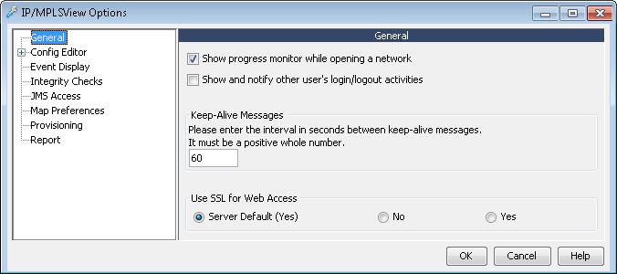
Show progress monitor while opening a network: The progress monitor when opening a network displays the current status, whether it be loading the network or creating the map.
Show and notify other user’s login/logout activities: This option can be used to pop up a status message in NorthStar Planner when another user has logged into NorthStar Planner, including details such as the user name, client PC name and client PC IP address.
Keep Alive Message: The server and client send keep-alive messages to make sure that the connection stays up. This value sets the message interval time in seconds.
Use SSL for Web Access: If this option is selected, then when NorthStar Planner redirects users to the Web Portal, it will direct them to a link prefixed with https using port 8443 rather than http on port 8091. By default this is determined by the Server Default setting, USE_SSL, in /u/wandl/bin/mplsenvsetup.sh.
Config Editor Options
The Config Editor Options window is used to set options for the Configuration Editor, which is a text editor enhanced for configuration files. There are also two sub-options windows which allow you to modify the colors and fonts used in the editor. For information on how to access the Config Editor, see Config Editor (Router and Switch).
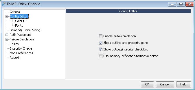
Enable auto-completion: Selecting this option enables the intelligent auto-completion of commonly-used configuration commands as you type.
Show outline and property pane: Selecting this option displays two extra panes on the right-hand side of the editor. The Config Editor divides each config file into blocks, based on significant keywords. The outline pane provides an outline view of the config file based on these blocks and allows you to quickly jump to a specific section of the config file. The property pane reveals information regarding the router and associated config file, such as IP address, vendor, version number, as well as the location of the config file.
Show output/integrity check list: Selecting this option displays the results of the integrity checks in a separate pane within the editor.
Use memory-efficient alternative editor: Selecting this option disables the configuration-enhanced text editor and uses the standard text editor when you open a router configuration file.
Config Editor > Fonts: select to configure the font used by the config editor.
Config Editor > Colors: select to configure the colors used by the config editor. See Set Color-Coding and Other Options for more details.
Path Placement Options
Depending on the hardware type, this option may contain additional fields than what is described below. For a description of those hardware-specific fields, see the hardware-specific guides.
Field |
Description |
|---|---|
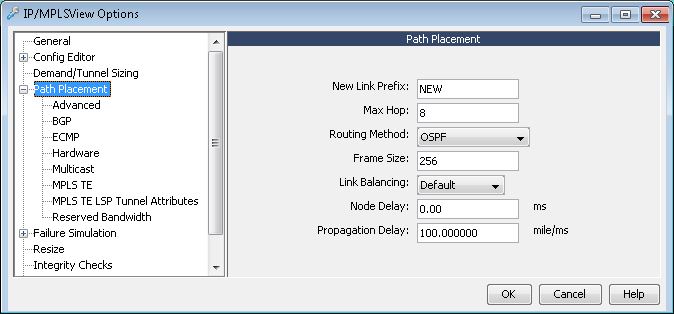
New Link Prefix |
The link prefix that gets used to generate the link name for newly added links. By default, this is set to “NONE” which means no link name is generated. |
Max Hop |
The maximum number of hops allowed for a demand path |
Routing Method |
This specifies the method NorthStar Planner will use to determine a demand’s path placement: for example, Constant Distance, Actual Mileage, Delay, Admin. Weight, OSPF, ISIS, IGRP, or EIGRP.
|
Frame Size |
This defines the average frame size, in bytes, used in overhead calculation for traffic utilization estimation and delay calculation. |
Link Balancing |
If there are parallel links between two nodes, this option is used to decide which link is used to route a demand/tunnel. The following options are supported:
|
Node Delay |
Sets the delay for the node. Delay is in milliseconds (ms). |
Propagation Delay |
Sets the propagation delay. Propagation delay is determined using the assumption that every 100 miles equals one millisecond of delay. |
Advanced
Field |
Description |
|---|---|
Placement Order |
This parameter affects the placement order of demands. Possible values are:
|
Path Selection Method |
This parameter influences path selection when more than one shortest path is found to route a demand. Possible values are:
|
Force PBR Check |
When set to True, this forces the program to check demands against Policy Based Routing (PBR) even if there is no destination IP address defined on the demand. When set to false, demands that do not have destination IP address defined are not checked against PBR. Demands that do have destination IP address defined are checked against PBR regardless of how this option is set. |
Ignore Multiprocess |
Only interfaces of the same OSPF process/routing instance are allowed to exchange routing tables and send traffic to one another. For what-if studies, however, this parameter can be set to true to ignore this requirement and to see how traffic would route if they were in the same OSPF process. For more details, refer to the NorthStar Planner Feature Guide chapter, Routing Instances. |
Ignore Max Delay |
If this option is selected, demands are placed even if they exceed the max delay constraint property specified for the demand. |
Allow Negative Available Capacity in Layer 3 |
This selection specifies whether the available bandwidth of trunks will or will not be checked during path placement. When Yes is selected, it is not checked. When No is selected, it is checked. Hardware default selection will depend on the hardware specification. |
Include Node’s Admin Weight in Path Length Calculation |
By default False, any admin weight on the node itself is not included in the path length calculation. If set to True, then the admin weight on the node is added to the path length calculation. |
BGP
Field |
Description |
|---|---|
IGP Override |
When both a BGP and IGP path are available between two ASs, by default the BGP protocol is treated as having the higher administrative distance/preference. If this option, IGP Override, is set to true, then the IGP route is used instead of the BGP route. If this option is set to false, the BGP route is used, as is usually the default in most networks. In the dparam file, set this parameter to true by setting IGPoverride=1. |
Check IBGP Policy |
IBGP Policies may be used to change the BGP next hop info when passing BGP tables from one speaker to another using IBGP neighbor definitions. To turn on IBGP policy checking, set this to true. For performance reasons, you may want to change this flag to false for a network without IBGP policies. In the dparam file, set this parameter to true by setting chkIBGPflag=1 (0 to skip IBGP policy checking). |
Use Live BGP Table If Available* |
Live BGP routing tables can be used to create a live BGP table object file that can be loaded into the program to route according to the live BGP routing table by specifying the livebgprtblobj file in the specification file. The live BGP routing table may have additional information about the BGP next hop to external IP addresses that is otherwise unavailable through the config files. Select True to route according to the live BGP routing table specified in the specification file. Select False to have the program route according to the BGP routing table information generated from the config files and any additional BGP protocol parameters that were entered into the BGP subnet file. In the dparam file, set this parameter to true by setting useliveBGPrtbl=1. |
ECMP
Field |
Description |
|---|---|
Max. ECMP Count |
This number specifies the maximum number of ECMP sub-flows that can be split from one original flow. |
Min. ECMP Flow BW |
This bandwidth value specifies the minimum bandwidth a flow must have in order to split it into sub-flows. |
Hardware
This window allows you to specify the bandwidth of each type of trunk in the network, a limit on the length of paths, and the demand priority scheme. The hardware type of the network is displayed for you, but cannot be changed in this particular window.
Field |
Description |
|---|---|
Hardware Type |
The current hardware type may be selected from the Hardware Options window. Note that the available list of device models is based on the switch libraries that have been licensed from Juniper Networks. |
Reverse Priority |
The reversepri parameter determines which demand priority scheme should be used by NorthStar Planner. "No" for larger numbers that have higher priority (1=lowest priority) and "Yes" if smaller numbers have higher priority (1=highest priority). |
Physical Hop Limit |
This number specifies the hop limit of the actual hardware and is used only in simulation mode, primarily during the Simulate Path Placement function. This parameter is not to be confused with the max hop parameter which is used during design aspects of NorthStar Planner. |
Bandwidth, Overhead |
The bandwidth and overhead fields indicate the trunk values which the program uses, by default, for the selected Hardware Type. If, for any reason, these values are inconsistent with your expected values, this Hardware Options window is the place to modify them. Bandwidth and link overhead are used in the routing and rerouting algorithms when determining demand placement. |
Multicast
Field |
Description |
|---|---|
Enable PIM |
This option allows you to enable or disable all links as PIM-enabled. |
PIM Mode |
This specifies the PIM mode for the multicast feature. |
MPLS TE
Field |
Description |
|---|---|
MPLS-Enabled Mode |
This option allows you to enable all links as MPLS-enabled, or have them set as specified per link in the Protocols tab of the Link window. |
Tunnel Parameters: Reuse ID of Deleted Tunnels |
This specifies whether or not IDs of deleted tunnels should be reused. This applies to Tunnel ID groups that are used to rename tunnel IDs to Cisco’s default tunnel ID format. When a tunnel that has been assigned a tunnel ID is deleted, whether or not its ID is reused is determined by this option. |
Bandwidth Model |
This determines how bandwidth for multiple classes is displayed in the Link window. User can choose between Maximum Allocation Model (MAM) and Russian Doll Model (RDM). Refer to the NorthStar Planner Feature Guide, chapter DiffServ Traffic Engineering Tunnels for further details on the RAM and MAM bandwidth models. |
GlbPool/RSVP |
This defines the percentage of bandwidth reserved on a link for global pool / RSVP. This setting is the default global setting for the entire network. |
SubPool/GB |
This defines the percentage of bandwidth reserved on a link for sub pool / GB (Guaranteed Bandwidth). This setting is the default global setting for the entire network. |
MPLS TE LSP Tunnel Attributes
Type over the bitxx to a name you want to be associated with your attributes on the Tunnels and links.
Reserved Bandwidth
Field |
Description |
|---|---|
Reserve Bandwidth File |
The Reserve Bandwidth File field indicates the path of the reserved bandwidth file that is being used, if any. To incorporate the reserved bandwidth file into the network model, you can import it using the File > Read, Network Files tab, Control Files category, rsvbwfile. The file specifies reserved bandwidth information for specific trunks. |
Ethernet Fat (%) |
Global parameter that indicates the default percentage of bandwidth to be reserved for ethernet trunks. This parameter can be overridden in the rsvbwfile. |
Default Fat (%) |
Global parameter that indicates the default percentage of bandwidth to be reserved for all trunks. This parameter can be overridden in the rsvbwfile. |
Default Fixed Fat |
Global parameter that indicates the default amount of bandwidth to be reserved for all trunks. Fixed fat is specified in either bits or kilobits. This parameter can be overridden in the rsvbwfile. |
Failure Simulation Options
Field |
Description |
|---|---|
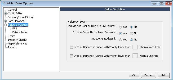
Include Never CanFail trunks in failure simulations |
This field specifies whether “CanFail = 0” trunks should be included in link failure simulations. A link marked as “CanFail = 0” represents a link that will never fail. A link marked as “CanFail = 1” represents a link that will fail. |
Exclude Currently Unplaced Demands |
This field specifies whether unplaced demands should be included in the failure simulation. Note that unless specified in this option, unplaced demands are listed along with failed demands in the node, link, and single line failure simulations. |
Include AS Node/Link |
If set to Yes, AS nodes and AS links are failed in the exhaustive node and link simulations, respectively. To exclude the AS nodes and AS links from the exhaustive simulations, set this option to No. |
Drop all Demands/Tunnels with Priority lower than <value> when a Node Fails |
During node failure simulation, demands and tunnels that are lower than the defined value are automatically dropped and will not be rerouted in the simulation results. |
Drop all Demands/Tunnels with Priority lower than <value> when a Link Fails |
During link failure simulation, demands and tunnels that are lower than the defined value are automatically dropped and will not be rerouted in the simulation results. |
FRR
This window defines the default FRR mode used during failure simulation batch scripts. If no FRR mode is specified in failure simulation batch scripts, the script will use the FRR mode specified in this window by default. The FRR modes are explained in the table below:
Normal |
Simulates the “normal” tunnel reroute. Does not consider the effect of the FRR detours during the simulation. Peak utilization reflects that during the “normal” situation. |
FRR only |
Simulates only the FRR detour. The resulting link peak utilization report reveals just the peak utilization experienced during the detour. |
FRR + Normal |
Simulates the FRR detour first followed by the normal primary tunnel reroute as established at the head-end router. The resulting link peak utilization report identifies the worst utilization, or max value of the transient detour and normal modes. Note:
A primary tunnel being detoured is marked down if it cannot be rerouted. |
Failure Report
Verbose Mode |
Specifies whether output results should be in detailed (verbose) or summary format. When in verbose mode, the program will draw colored lines representing failed and rerouted demands on the topology map during interactive failure simulations. When verbose mode is disabled, no such lines are drawn on the map during interactive failure simulations. |
Sequential Mode |
This option allows you to sequentially step through a given simulation run. You can advance to the next simulation by clicking the left mouse button. If sequential mode is set to “No”, the simulation will automatically run to completion. |
Trace File |
This option specifies whether a trace file should be used to record simulation output results. |
Display Paths at Failed Nodes |
Specifies whether paths that originate or terminate at a failed node should be displayed in the simulation output. All such demands will obviously be brought down in a node failure. |
Exclude Path Required Demands in Failure Statistics |
Specifies whether demands that failed because of path required criteria should be excluded in the simulation. If a demand is defined with a path required field and that path is not available for some reason, the demand will fail. The program will not attempt to reroute the demand on an alternate path. |
Report Tunnel Utilization |
When running an exhaustive failure simulation in layer 3 and selecting Generate Peak Utilization Report, the Tunnel Peak Utilization report generation can be turned off by setting this to No. |
Resize Options
The Resize Options may be used to tune and optimize the current backbone topology. Accessed from Design > Backbone > Resize, this design feature will modify the current link bandwidths to maximize utilization. Three resize options can be chosen: based on the current peak simulation results, based on normal utilization, or based on exhaustive node/link/SRLG failure simulation results. This analysis and modification presume that there might be unnecessary bandwidth in certain links and also take into account the additional bandwidth necessary during demand rerouting. When the resize option is performed, NorthStar Planner replaces links in the network in accordance with the Link Type Candidate selected in the Design Options window.
Field |
Description |
|---|---|
Additional Trunk Penalty |
Added penalty during Resize for replacing large trunks with multiple trunks of smaller size. |
Types in Tariff |
Valid link types are taken from the current tariff table |
AGGR |
For the aggregate link type, valid link types are based on multiples of a specified unit, for example, if the unit is 10G, then the resize will choose multiples of 10G, for example, AGGR10G, AGGR20G, etc. |
Map Preferences
The color scheme and display options of the topology map may be changed in the Map Preferences window. Click on any color to change it. You may also change options related to the display of the network topology.
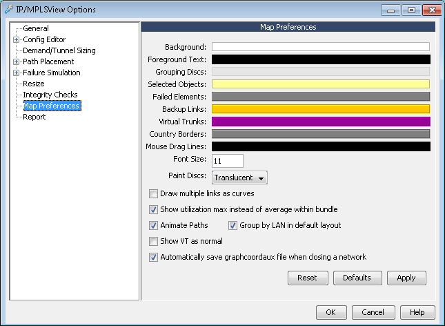
Field |
Description |
|---|---|
Background |
This selects the color for the background on the topology window. |
Foreground Text |
This selects the color for text labels and other foreground items. |
Grouping Discs |
This selects the color for any groups in the topology defined by you. A group is a region that can be set by you. |
Selected Objects |
This is the color for any user-selected objects in the topology window. |
Failed Elements |
This is the color for failed elements (links, nodes, facilities, etc.) |
Backup Links |
Allows you to set the color for back-up links. |
Virtual Trunks |
Allows you to set the color for virtual trunks. |
Country Borders |
This selects the color of country borders when the country map is displayed in the Topology window. |
Mouse Drag Lines |
Specifies the color of the lines shown when you click and drag the mouse in the topology window. |
Font Size |
You may increase or decrease the font size of text (such as node labels, link labels, etc.) that appear in the Topology window. |
Paint Discs |
Allows you to select a method for painting discs for groups on the topology map. The choices are: translucent, quick rings, opaque and none. On some machines, choosing quick rings or opaque may improve performance. |
Draw multiple links as curves |
When checked, the program will draw multiple links between a given node pair as curves for better display of the paths. |
Show utilization max instead of average within bundle |
If Draw multiple links as curves is not checked, then multiple links are drawn as one bundled link. When Show max is not checked, the utilization displayed from mouse-over in the bottom bar of the map is the Average utilization of the multiple links. When Show max option is checked, the utilization displayed from mouse-over in the bottom bar of the map is the Highest utilization of the multiple links. |
Animate Distribute Points |
When checked, this option will animate the Distribute Points function in the Topology window. Refer to the Topology chapter for more information. |
Animate Paths |
This option will animate the path between two points in the topology, showing the direction the path is flowing. Turning off the animation will improve the performance of the system. |
Group by LAN in default layout |
Selecting this option will cause the initial layout when opening a network to attempt to layout nodes in such a way that minimizes LAN link lengths as much as possible. Since this only affects the initial layout when opening a network, changes made to this option will not have any effect until a new network is opened. This option should be turned off if nodes connected by ethernet can be separated by longer distances. |
Show VT as normal |
Displays virtual trunks as regular trunks. When this option is not checked, virtual trunks are always displayed in the color chosen above. |
Automatically save graphcoordaux file when closing a network |
By default, the graphcoordaux file is automatically saved when closing a network to avoid losing auxiliary changes made to the map, such as map legend settings. Uncheck to disable this feature. |
Reset |
Resets options to the previous settings. |
Defaults |
Sets options to the system default settings. |
Apply |
Applies new settings immediately without closing the Map Preferences window. |
OK |
Applies new settings and closes the dialog window. |
Cancel |
Cancels the any changes. |
Help |
Opens the help documentation. |
Report Options
The Report Options window is used to customize the format of reports generated through NorthStar Planner.
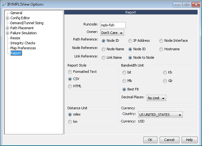
Field |
Description |
|---|---|
Runcode |
The runcode is the filename extension appended to the end of each output file generated in a particular run of NorthStar Planner. It allows you to distinguish amongst several sessions using the same data set. To specify a runcode, you should type the desired input in the Runcode text box of the Report Options window. This runcode may consist of a combination of alphanumeric characters. Subsequently, any report files generated is in the format filename.runcode. It is important to use unique runcodes. Otherwise, there is a danger of accidentally overwriting existing files with the same names. |
Owner |
You can choose to view report data related only to the specified owner(s). |
Path Reference |
This option sets the display preference for paths in the report. |
Node Reference |
In report files, nodes may be referred to by either node name, node ID, or hostname. |
Link Reference |
In report files, links may be referred to by using one of two conventions. The standard method is to represent a link by the node pair that defines it. An alternative method is to associate a user-defined link name with that link. If a link name is not defined for a link, the node pair naming convention is used. To use either method, select the appropriate box in the Link Reference section. Note: This option applies not just to report files, but also to some console messages, for example, those displayed during an Exhaustive Single Line Failure. |
Report Style |
You may specify the file format of subsequent reports in the Report Options section. Three formats are supported: Formatted Text, CSV, and HTML. Formatted Text is simply standard ASCII output that may be viewed in any text viewer without additional preprocessing. Comma delimited format (CSV) outputs text so that a comma is used as a separator for each distinct field in the report. This is most often used to import report files into spreadsheet applications, and can be viewed using the Report Viewer. Finally, Hypertext Markup Language format (HTML) outputs reports in HTML-compliant format so that the report files can be directly viewed by web page browsers. |
Bandwidth Unit |
The bandwidth unit used in reports may be selected in the Bandwidth Unit section of the Report Options menu. The Best Fit option can be used when there is a large number of different bandwidth types being used. Reports generated with the Best Fit option may contain Bits, Kilobits, or Megabits depending on the available field space. Note that cells may only be selected for ATM hardware devices. In the ATM case, values entered in bits are converted to the appropriate number of cells using a conversion formula. Decimal Places is the number of digits to the right of the decimal point displayed in reports. |
Distance Unit |
The distance unit used in report files may be specified in the Report Options menu. To specify a distance unit, go to the Distance Unit section and select an appropriate one. The available options are miles and kilometers (km). |
Currency |
Sets the currency unit for NorthStar Planner. To specify a currency, first go to the Currency section. Then, select a country from the drop-down combo box listing the available countries. Once this is done, the selected country's associated currency unit is used in subsequent monetary values. Note:
For the EURO currency used in various European countries, select ER EURO from the country list. The Euro unit is displayed as ER. |
