Provision Multiple LSPs
To provision multiple LSPs at once in the network topology, navigate to Network Management > Provisioning > Provision Multiple LSPs. The Provision Multiple LSPs window has Properties, Advanced, Design, Scheduling, and User Properties tabs. The Scheduling and User Properties tab fields are essentially the same as for provisioning single LSPs.
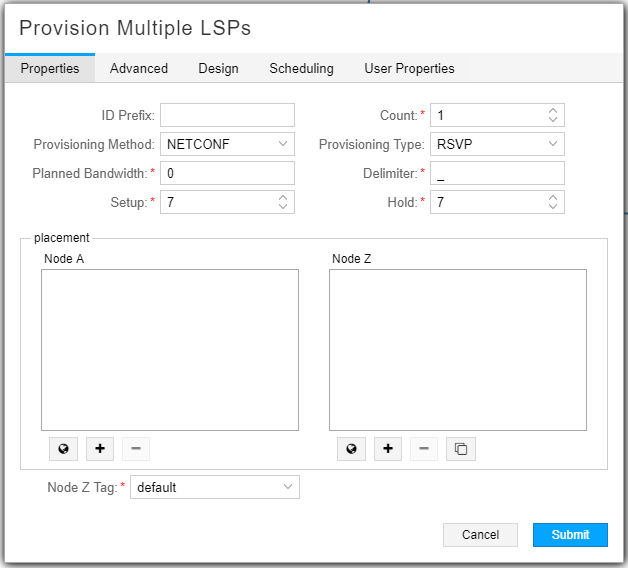
The Provision Multiple LSPs Properties is displayed as shown in Figure 1.

Table 1 describes the fields available in the Properties tab.
Field |
Description |
|---|---|
ID Prefix |
You can enter a prefix to be applied to all of the tunnel names that are created. If left blank, this field defaults to “PCE”. |
Provisioning Method |
Required. Use the drop-down menu to select PCEP or NETCONF. The default is NETCONF. See Templates for Netconf Provisioning for information about using customized provisioning templates to support non-Juniper devices. Note:
For IOS-XR routers, NorthStar LSP NETCONF-based provisioning has the same capabilities as NorthStar PCEP-based provisioning. |
Planned Bandwidth |
Required. Bandwidth immediately followed by units (no space in between). Valid units are:
Examples: 50M, 1000b, 25g. If you enter a value without units, bps is applied. |
Setup |
Required. RSVP setup priority for the tunnel traffic. Priority levels range from 0 (highest priority) through 7 (lowest priority). The default is 7, which is the standard MPLS LSP definition in Junos OS. |
Count |
Required. Number of copies of the tunnels to create. The default is 1. For example, if you specify a count of 2, two copies of each tunnel are created. |
Provisioning Type |
Required. Use the drop-down menu to select RSVP or SR (segment routing). |
Delimiter |
Required. Delimiter character used in the automatic naming of the LSPs. |
Hold |
Required. RSVP hold priority for the tunnel traffic. Priority levels range from 0 (highest priority) through 7 (lowest priority). The default is 7, which is the standard MPLS LSP definition in Junos OS. |
Node A column |
Select the Node A nodes. If you select the same nodes for Node A and Node Z, a full mesh of tunnels is created. See Table 2 for selection method options. |
Node Z column |
Select the Node Z nodes. If you select the same nodes for Node Z and Node A, a full mesh of tunnels is created. See Table 2 for selection method options. |
Node Z Tag |
Select a tag from the drop down menu. Tags are set up in the Modify Node window, Addresses tab. In the Addresses tab of the Modify Node window, you have the option to add destination IP addresses in addition to the default IPv4 router ID address, and assign a descriptive tag to each. You can then specify a tag as the destination IP address when provisioning an LSP. |
Under the Node A and Node Z columns are several buttons to aid in selecting the tunnel endpoints. Table 2 describes how to use these buttons.
Button |
Function |
|---|---|
(world) |
Select one or more nodes on the topology map, then click the globe button to add them to the Node column. |
(plus) |
Click the plus button to add all of the nodes in the topology map to the Node column. |
(minus) |
Select a node in the Node column and click the minus button to remove it from the Node column. Ctrl-click to select multiple nodes. |
(copies) |
Click the right-arrow button on the Node Z side to add all of the nodes in the Node A column to the Node Z column. |
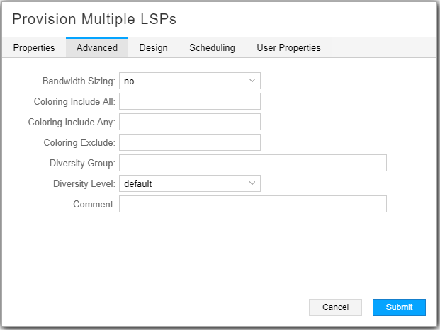
On the Advanced tab, you can specify coloring parameters as shown in Figure 2 and described in Table 3.

Field |
Description |
|---|---|
Bandwidth Sizing |
If set to yes, the LSP is included in periodic re-computation of planned bandwidth based on aggregated LSP traffic statistics. Note:
Bandwidth sizing is supported only for PCE-initiated and PCC-delegated LSPs. Although nothing will prevent you from applying this attribute to a PCC-controlled LSP, it would have no effect. See Bandwidth Sizing for more information. |
Coloring Include All |
Double click in this field to display the Modify Coloring Include All window. Select the appropriate check boxes. Click OK when finished. |
Coloring Include Any |
Double click in this field to display the Modify Coloring Include Any window. Select the appropriate check boxes. Click OK when finished. |
Coloring Exclude |
Double click in this field to display the Modify Coloring Exclude window. Select the appropriate check boxes. Click OK when finished. |
Diversity Group |
Name of a group of tunnels to which this tunnel belongs, and for which diverse paths is desired. |
Diversity Level |
Use the drop-down menu to select the level of diversity as default, site, link, or SRLG. |
Comment |
Enter free-form comment. |
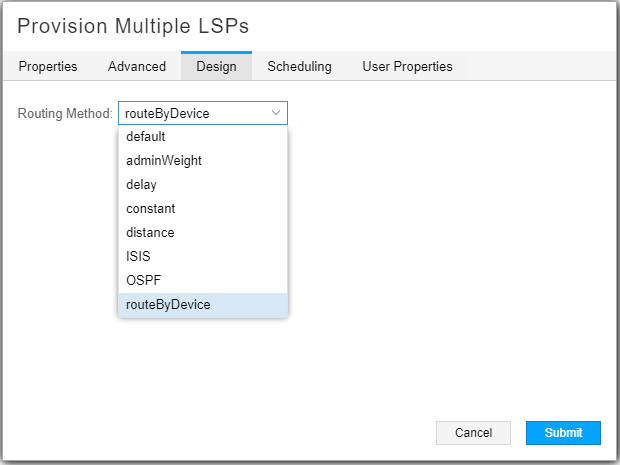
The Design tab, shown in Figure 3, allows you to use a drop-down menu to select a routing method. Available options include default (NorthStar computes the path), adminWeight, delay, constant, distance, ISIS, OSPF, and routeByDevice (router computes part of the path).

Scheduling relates to bandwidth calendaring. By default, tunnel creation is not scheduled, which means that tunnels are provisioned immediately upon submission. Click the Scheduling tab in the Provision Multiple LSPs window to access the fields for setting up the date/time interval.
Select Once to select start and end parameters for a single event. Select Daily to select start and end parameters for a recurring daily event. Click the calendar icon beside the fields to select the start and end dates, and beginning and ending times.
The time zone is the server time zone.
In the User Properties tab, you can add provisioning properties not directly supported by the NorthStar UI. For example, you cannot specify a hop-limit in the Properties tab when you provision an LSP. However, you can add hop-limit as a user property in the User Properties tab. This works the same way as it does when provisioning single LSPs.
