Device Profile and Connectivity Testing
Completing device profiles is a prerequisite to running collection tasks. Navigate to Administration > Device Profile to open the Device Profile window where you can:
Set up or modify the device list. Initially, the device list contains all the devices discovered from the traffic engineering database (TED). The device IP address (if not already discovered) and the PCEP IP address for each device are required. The PCEP IP address is the local address of the PCC located in the PCE statement stanza block.
Supply a hostname for each router for OSPF networks. This is necessary because the TED does not contain hostnames for OSPF networks.
Specify an MD5 key to secure PCEP communication between the NorthStar Controller and the PCC.
Specify device SNMP parameters for SNMP connectivity.
Test connectivity of devices using ping, SSH, SNMP, and NETCONF.
When the Device Profile window is first opened, no automatic comparison between the live network and the configured device list is performed. This means you might not see discrepancies immediately. You can manually perform the comparison by clicking the Sync with Live Network button at the top of the window. When the device list is opened for the very first time, it is blank until you perform a Sync with Live Network.
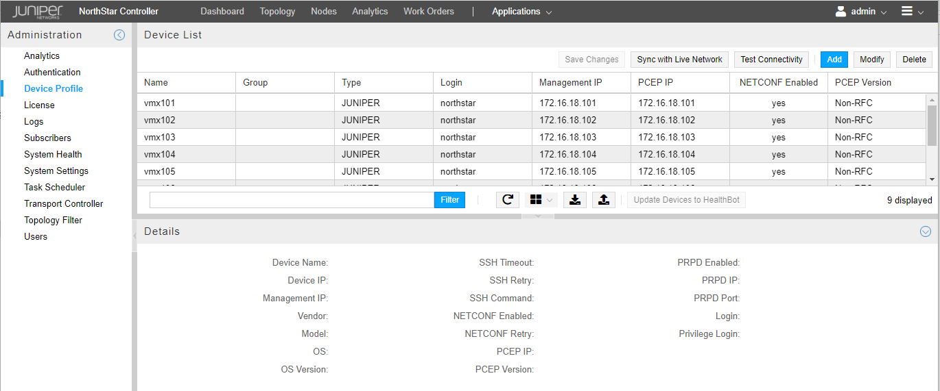
Figure 1 shows the Device Profile window, including the device list in the upper pane and details about the highlighted device in the lower pane.
Device List Pane
The Device List pane shows all the devices in the profile along with many of their properties. You can change the order of the devices in the list by clicking and dragging rows. Sorting, column selection, and filtering options are available when you hover over a column heading and click the down arrow that appears. Figure 2 shows an example.
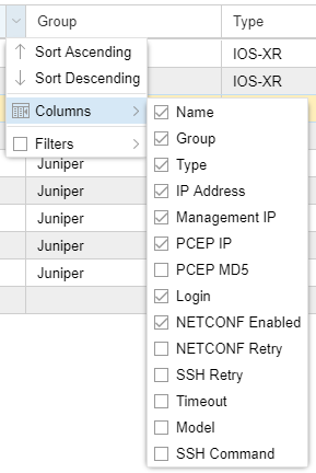
You can filter the devices that are included in the display by activating a filter on any column. See Sorting and Filtering Options in the Network Information Table for a description of the column filtering functionality, along with an example.
The buttons across the top and bottom of the Device List pane perform the functions described in Table 1. Button labels are displayed when you hover over icon buttons.
Button |
Function |
|---|---|
Save Changes |
Saves the device profile changes. The button becomes active when modifications or edits have been made to entries or fields in the device list. When the button is active, you must click it to finalize your changes. |
Sync with Live Network |
Synchronizes devices with the live network. This function does not delete devices from the selected profile that do not exist in the live network, but it does add devices that are missing from the live network, and it synchronizes all devices with a corresponding live network device. When you click Sync with Live Network, this is what happens behind the scenes:
|
Test Connectivity |
Tests connectivity on the selected devices. |
Add |
Adds a device. |
Modify |
Modifies the selected device. |
Delete |
Deletes the selected device. |
Filter |
Filters the list of devices according to the text you enter. |
(Reload Device Profiles) |
Reloads the device profiles. This is useful when you are modifying a device entry and then realize that you don’t want to save it. Reload will reload the device list back to the last saved state. |
(Device Grouping) |
Offers device group management and group display options. |
Export Device Profiles |
Exports device profiles to a comma separated values (CSV) file named DeviceProfiles.csv. |
Import Device Profiles |
Imports devices from a CSV file. This is particularly useful when there are a large number of devices to add. Clicking the button opens the Import Devices from CSV window where you browse to the CSV file and specify the appropriate delimiter. A preview of the data appears in the Data Preview box. |
Update Devices to HealthBot |
Updates to HealthBot all the device information for all the Juniper devices that are managed by NorthStar. You see a success message when the process is complete. For this button to be available, you must have the collector_type parameter set to HealthBot (as opposed to Elasticsearch) in the northstar.cfg file. |
You can perform many of these functions on multiple devices simultaneously. To select multiple devices, Ctrl-click or Shift-click the device rows and then click the button for the function you wish to perform.
Test Connectivity
The Test Connectivity button opens the Profile Connectivity window shown in Figure 3.
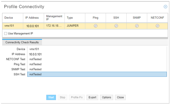
Click the Use Management IP check box if the devices to be tested have management IP addresses specified for out-of-band use.
Click Options to open the Test Connectivity Options window shown in Figure 4.
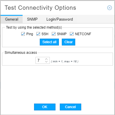
In the General tab, you can:
Specify which test methods you want to use (Ping, SSH, SNMP, NETCONF). Multiple methods are allowed (by default, all methods are tested). To select or deselect methods, click the corresponding check boxes.
Allow for concurrent access of a number of devices by specifying a simultaneous access limit from 1 to 16. The default is 7.
In the SNMP tab, you can add optional SNMP get community string(s), one per line. If an SNMP connectivity check fails with the community string specified in the device profile (SNMP Parameters tab), these additional community strings are tried until one succeeds.
In the Login/Password tab, you can enter alternate login credentials to be used in case of login/password failure.
Click OK to submit your selections and close the Test Connectivity Options window.
In the Profile Connectivity window, click Start to begin the connectivity test. You can click Stop if the test fails to complete quickly. The test is complete when the green (pass) or red (fail) status icons are displayed. Figure 5 shows an example.
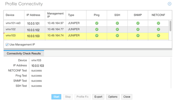
In SNMP connectivity testing, the host name and device type (vendor) are polled and are auto-populated in the test results if the information was previously missing or incorrect in the device profile. A red triangle in the upper left corner of a field in the test results indicates that a change was automatically made. You can see an example in the Device column in Figure 5. To propagate those changes to the device profile, click Profile Fix at the bottom of the Connectivity Test Results window.
To display the detailed test results for an individual device in the lower part of the window, click the device row in the upper portion of the window, even if you only tested connectivity for a single device. Click Export to export the connectivity results report as a CSV file.
The Start button remains unavailable after test completion until you close the window and reopen it to begin a new connectivity test.
Add Device
The Add button opens the Add New Device window shown in Figure 6.
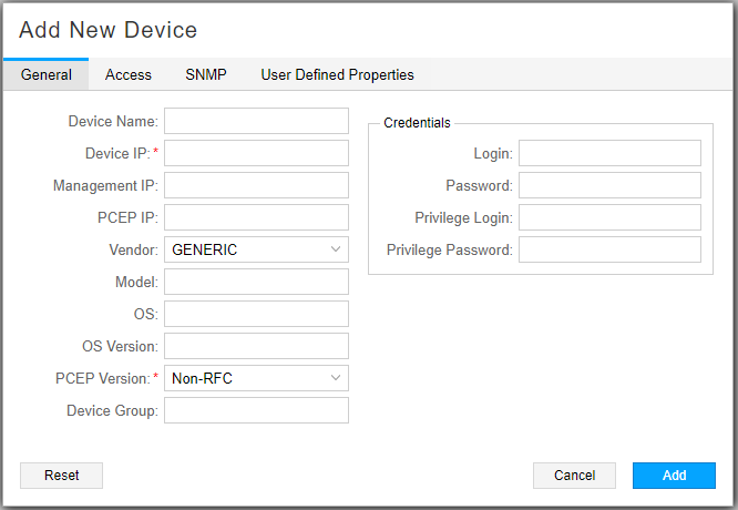
Table 2 describes the data entry fields under the General tab.
Field |
Description |
|---|---|
Device Name |
Name of the network device, which should be identical to the hostname. During configuration collection, the software uses this name as part of the name of the collected configuration file. The configuration filename uses the format ip.name.cfg. If the device name is left blank, the configuration filename uses the format ip.cfg. |
Device IP |
Required field: IP address of the network device. |
Management IP |
Management IP address for the device. NorthStar Controller first attempts connection using the management IP address if it is specified, and then the IP address. Note:
The management IP address is required for out-of-band management access. |
PCEP IP |
The local address of the PCC located in the PCE statement stanza block. Note:
We highly recommend that this field be populated. |
Vendor (Type) |
Select the device vendor from the drop-down menu. The default is GENERIC. The vendor is displayed in the Device List under the column heading Type. |
Model |
Model number of the device. |
OS |
Type of operating system installed on the device. |
OS Version |
Version number of the operating system build installed on the network device. The default value is > 14.2x. Note:
For routers configured with PCEP using Junos OS Release 14.2x and earlier, enter <= 14.2x for this parameter. |
PCEP Version |
Required field. Use the drop-down menu to select:
See PCEP Version and RFC 8231/8281 Compliance for more information about PCEP version and RFC 8231/8281 compliance. |
Device Group |
Device group name you assign to the device, such as a regional group. Note:
A device can only have one group designation. |
Login |
Login ID for the network device. |
Password |
Password for the network device. |
Privilege Login |
Login ID for situations that require a higher-security login. |
Privilege Password |
Password for situations that require a higher-security login. |
We recommend you do not use the credentials of Junos OS root users when running device collection. NorthStar Controller will not raise a warning when such credentials are used, even if the task fails.
Table 3 describes the data entry fields under the Access tab.
Field |
Description |
|---|---|
SSH Timeout |
Number of milliseconds after which a connection attempt times out. The default is 300. To enter a different value, type the number of milliseconds in the field or use the up and down arrows to increment or decrement the displayed value. |
SSH Retry |
Number of times a connection to the device is attempted. The default is 3. To enter a different value, type the number of retries in the field. |
SSH Command |
Command to use for SSH connection. The default is ssh. To enter
a different value, type the command in the field. Include the full
path of the command and options used for ssh, such as |
Enable Netconf |
Select this checkbox to enable NETCONF communication to the device. |
Enable Bulk Commit |
Select this checkbox to allow NorthStar to do a single commit instead of multiple commits when you provision multiple LSPs on the same router. Note:
This is mandatory for P2MP-TE. |
Netconf Retry |
Enter the number of times a NETCONF connection is to be attempted. The default is three. Note:
A value of 0 means an unlimited number of retries - connection attempts never stop. |
PCEP MD5 String |
Message Digest 5 Algorithm (MD5) key string, also configured on the router. Configuring MD5 provides information on configuring MD5 authentication. Note:
All the routers in the network must have their PCEP IP addresses in the profile. This is especially important if any router in the network is configured with an MD5 authentication key. |
Enable PRPD |
Click the check box to enable programmable routing protocol process (PRPD) on the device. This is required for EPE. |
PRPD IP |
IP address for PRPD on the device. The default is the router ID (router’s loopback address). If you leave the field empty, the default is used. |
PRPD Port |
Port on the router that NorthStar can use to establish a PRPD session. The default is 50051. |
The fields on the SNMP Parameters tab are required to set up for SNMP collection. The SNMP parameters are shown in Figure 7 and described in Table 4.
Consult your hardware and operating system software guides to understand the SNMP parameter values that are possible with your hardware/software combination.
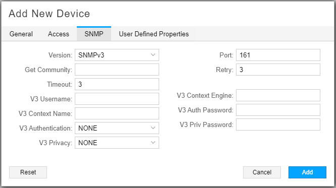
SNMP Parameter |
Description |
|---|---|
Version |
Use the drop-down menu to select SNMPv1, SNMPv2c, or SNMPv3. The default is SNMPv2c. |
Port |
SNMP port. The default is 161. Must match the port configured on the router. |
Get Community |
SNMP get community string as configured on the router. The default is “public” if you leave it blank. |
Retry |
Number of times connection will be attempted. The default is 3. |
Timeout |
Number of seconds after which connection attempts will stop. The default is 3. |
If you select SNMPv3 as the version, the additional fields described in Table 5 become available.
SNMP Parameter |
Description |
|---|---|
V3 Username |
Name that identifies the SNMPv3 user. |
V3 Context Name |
Context name, unique within an SNMP entity. |
V3 Authentication |
Possible values are NONE (default), MD5, SHA-1. |
V3 Privacy |
Possible values are NONE (default), DES, 3DES, AES (128-bit encryption only). Note:
As of Release 6.1.0, NorthStar does not support AES 192-bit and AES-256 encryption, although they are supported on Cisco devices. |
V3 Context Engine |
Unique identifier for an SNMP entity that may realize an instance of a context with a particular Context Name. |
V3 Auth Password |
The password must be at least eight characters long and can include alphabetic, numeric, and special characters. It cannot include control characters. |
V3 Priv Password |
SNMPv3 user’s privacy password, generally 8-12 characters in length. |
In the User Defined Properties tab, you can add properties not directly supported by the NorthStar UI.
Click Submit to complete the device addition. The new device appears in the device list.
Modify Device
The Modify button opens the Modify Device(s) window, which has the same fields as the Add New Device window. Edit the fields you want to change and click Submit. Click Save Changes to complete the modification. You can wait until you have completed all your device modifications to click Save Changes, which will have become active to flag that there are unsaved changes.
To modify one or more fields in the same way for multiple devices, Ctrl-click or Shift-click to select the devices in the device list and click Modify. On the resulting Modify Device(s) window, you can make changes that affect all the selected devices.
As an alternative to opening the Modify Device(s) window, you can change some of the device properties directly in the Device List pane by double-clicking the fields.
Delete Device
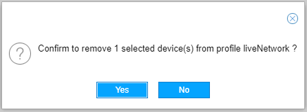
To delete a device, select the device row in the Device List and click Delete. A confirmation window is displayed as shown in Figure 8.
Click Yes to complete the deletion.
-
If a devices’s router ID is changed in the network, you should first delete the device from the device profile, and then perform “sync with live network” to re-discover and add the device with its new router ID into the device profile.
-
If you delete a device from the liveNetwork profile, you are not deleting it from the live network itself. You can restore the device to the profile using the Sync with Live Network button.
Device Grouping Options
With device grouping, you can group devices in ways that are independent of topological groups. Since NETCONF task collection supports collection by device profile group, one way to use this functionality is to manage NETCONF sub-collection tasks by group.
When you click the down arrow beside the Device Grouping icon, the two options displayed are:
Toggle Device Grouping
Manage Device Grouping
Select Toggle Device Grouping to either display the devices in the Device List according to their assigned groups, or not. Figure 9 shows an example of a device list in which device grouping is toggled on.
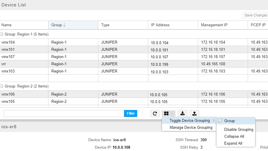
To return to the ungrouped device list, select Disable Grouping. To display just the group names without displaying the group members, select Collapse All. To return to the grouped display in which the group members are also shown, select Expand All.
Select Manage Device Grouping to open the Manage Device Groups window as shown in Figure 10.
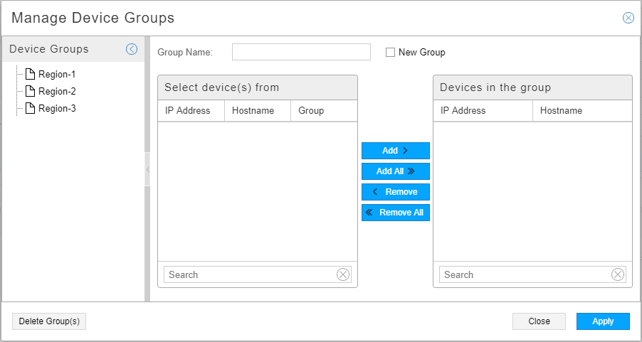
Existing groups are listed on the left side. Click the name of an existing group to display its members in the “Devices in the group” list on the right. All other devices are listed in the “Select device(s) from” list where you can select devices to add.
To delete a group, click the name of an existing group on the left and click Delete Group(s) at the bottom. This action removes the group assignment from the member devices. Groups with no members are automatically deleted.
To create a new group and add devices to it, type the group name at the top and click the New Group check box. All devices are then listed in the “Select device(s) from” list so you can choose the group members. Figure 11 shows an example. If you add devices that are already assigned to a group, the new assignment removes the previous assignment.
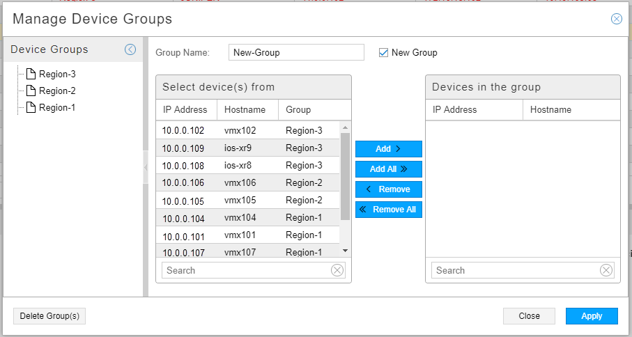
Click Apply to save your work.
You can also assign a group to a device profile in the Add New Device or Modify Device(s) window (General tab). The Manage Device Groups window is particularly useful for making changes to multiple devices at once.
Device Detail Pane
The Device Detail pane displays the properties of the device that is highlighted in the Device List pane. There are two ways to minimize this pane:
Click the down arrow at the top center of the pane. Click the up arrow to maximize the pane.
Click the down arrow in the top right corner of the pane. Click the up arrow to maximize the pane.
Click and drag the top margin of the pane to resize the pane.
PCEP Version and RFC 8231/8281 Compliance
When you configure a device profile, NorthStar automatically stores a corresponding entry in the internal persistent cache that represents the PCEP version you configured. You set the PCEP version in the device profile (in the General tab) as either Non-RFC, RFC Compliant, or 3rd party PCC. Table 6 shows a summary of the PCEP version options.
Configured in Device Profile |
Internal Cache (Value of 1 is not used) |
Notes |
|---|---|---|
Non-RFC (default) |
0 |
Indicates that you do not want to use RFC 8231/8281 compliance and IANA code points for Association, S2LS Objects, and P2MP-IPv4-Lsp-Identifier TLV. This setting is appropriate for:
|
RFC-Compliant |
2 |
Sets IANA code points for Association, S2LS Objects, and P2MP-IPv4-Lsp-Identifier TLV. Also makes the system compliant with RFC 8231/8281. Note:
You must be using Junos OS Release 19.x or later to run in RFC 8231/8281 compliant mode. |
3rd party PCC |
3 |
Indicates that the device is something other than a Juniper Networks device. |
In the internal cache, the PCEP version is stored as a map of the PCC IP address and the PCEP version. For example:
192.168.2.100:2
192.168.2.200:2
The IP address is the PCC IP used to establish the PCEP session. This is the IP address the PCC uses as the local IP address and is the same as appears in the PCC_IP field in the web UI device profile for the device.
Whenever a device profile is updated in the NorthStar web UI, the PCEP version is also updated in the internal cache and reloaded by the PCE server, so there is no need to manually restart the PCE server to capture the updates.
Logical Systems
Some networks include both a physical topology and a logical topology. An example of how that could look in the NorthStar UI topology view is shown in Figure 12. In this example, the physical and logical layers are not connected, but they could be, depending on your network.
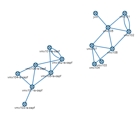
Logical nodes (and LSPs that incorporate logical nodes) are fully supported by NorthStar, but somewhat differently from physical nodes:
Logical topology is discovered automatically via BGP-LS. See Configuring Topology Acquisition in the NorthStar Controller Getting Started Guide for more information.
LSPs originating from a logical system cannot be discovered directly by PCEP. Instead, you run device collection for physical devices and any corresponding LSPs originating from logical devices are imported into the network information table, under the tunnel tab. The correlation between the physical and logical systems are established via device collection.
In the network information table in NorthStar, display the optional columns Physical Hostname and Physical Host IP so you can confirm that NorthStar successfully correlated the physical and logical nodes when it performed device colleciton.
Because PCEP is not supported for logical devices, it is not possible for NorthStar to obtain real time topology updates for logical devices. We recommend periodic device collection to compensate for this limitation.
Device collection must be run before you attempt to create LSPs that incorporate logical nodes because otherwise, the logical nodes are not available as selections for Nodes A and Z in the Create LSP window. In the Create LSP window, you must specify NETCONF as the Provisioning Method (not PCEP) when the LSP incorporates logical nodes.
For more information about logical nodes and provisioning LSPs that incorporate them, see Provision LSPs.
Configuring MD5
MD5 can be used to secure PCEP sessions as described in RFC 5440, Path Computation Element (PCE) Communication Protocol (PCEP). MD5 authentication must be configured on both the NorthStar Controller (in the Device Profile window) and on the router (using the Junos OS CLI). The authentication key must be the same in both configurations. The device profile acts as an “allowlist” when MD5 is configured. The NorthStar Controller does not report LSPs or provision LSPs for the routers not included in the device profile.
The first time MD5 is enabled on the router, all PCEP sessions to routers are reset to apply MD5 at the system level. Whenever the MD5 enabled status on a router or the MD5 key changes, that router resets the PCEP connection to the NorthStar Controller.
The first four steps are done in the NorthStar Controller Device Profile window, to configure MD5 for the PCEP session to a router.
Select a router in the Device List pane.
Click Modify to open the Modify Device(s) window.
In the MD5 String field (Access tab), enter the MD5 key string. Click Modify.
Click Save Changes to save your changes. The PCEP MD5 Configured field for the router changes from no to yes.
Note:All the routers in the network must have their PCEP IP addresses in the profile. When you save your changes, you might receive a warning, reminding you of this.
The final step is done in the Junos OS CLI on the router, to configure MD5 for the PCEP session to the NorthStar Controller.
Use the set authentication-key command at the [edit protocols pcep pce] hierarchy level to configure the MD5 authentication key.
user@pcc# set protocols pcep pce pce-id authentication-key md5-key


