Installation Prerequisites on Ubuntu
To successfully install and deploy a Paragon Automation cluster, you must have a control host that installs the distribution software on multiple cluster nodes. You can download the distribution software on the control host and then create and configure the installation files to run the installation from the control host. You must have Internet access to download the packages on the control host. You must also have Internet access on the cluster nodes to download any additional software such as Docker and OS patches. The order of installation tasks is shown at a high level in Figure 1.

Before you download and install the distribution software, you must configure the control host and the cluster nodes as described in this topic.
Prepare the Control Host
The control host is a dedicated machine that orchestrates the installation and upgrade of a Paragon Automation cluster. It carries out the Ansible operations that run the software installer and install the software on the cluster nodes as illustrated in Control Host Functions.
You must download the installer packages on the Ansible control host. As part of the Paragon Automation installation process, the control host installs any additional packages required on the cluster nodes. The packages include optional OS packages, Docker, and Elasticsearch. All microservices, including third-party microservices, are downloaded onto the cluster nodes. The microservices do not access any public registries during installation.
The control host can be on a different broadcast domain from the cluster nodes, but you must ensure that the control host can use SSH to connect to all the nodes.
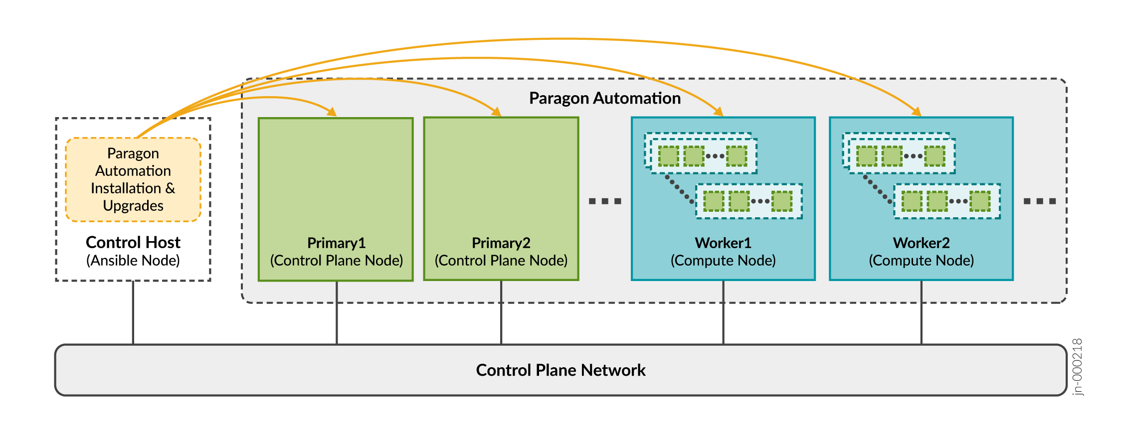
After installation is complete, the control host plays no role in the functioning of the cluster. However, you'll need the control host to update the software or any component, make changes to the cluster, or reinstall the cluster if a node fails. You can also use the control host to archive configuration files. We recommend that you keep the control host available, and not use it for something else, after installation.
Prepare the control host for the installation process as follows:
Prepare Cluster Nodes
- Paragon Automation and the managed devices
- Paragon Automation and the network administrator
We recommend that you place all the nodes in the same broadcast domain. For cluster nodes in different broadcast domains, see Configure Load Balancing for additional load balancing configuration.
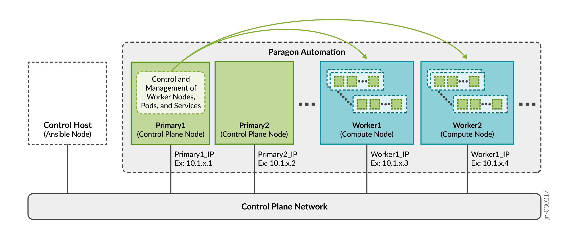
As described in Paragon Automation System Requirements, you can install Paragon Automation using a multinode deployment.
You need to prepare the cluster nodes for the Paragon Automation installation process as follows:
Virtual IP Address Considerations
A pod is the smallest deployable unit of computing created and managed in Kubernetes. A pod contains one or more containers, with shared storage and network resources, and with specific instructions on how to run the applications. Containers are the lowest level of processing, and you execute applications or microservices in containers.
The primary node in the cluster determines which worker node will host a particular pod and containers.
You implement all features of Paragon Automation using a combination of microservices. You need to make some of these microservices accessible from outside the cluster as they provide services to end users (managed devices) and administrators. For example, you must make the pceserver service accessible to establish Path Computation Element Protocol (PCEP) sessions between provider edge (PE) routers and Paragon Automation.
You need to expose these services outside of the Kubernetes cluster with specific addresses that are reachable from the external devices. Because a service can be running on any of the worker nodes at a given time, you must use virtual IP addresses (VIPs) as the external addresses. You must not use the address of any given worker node as an external address.
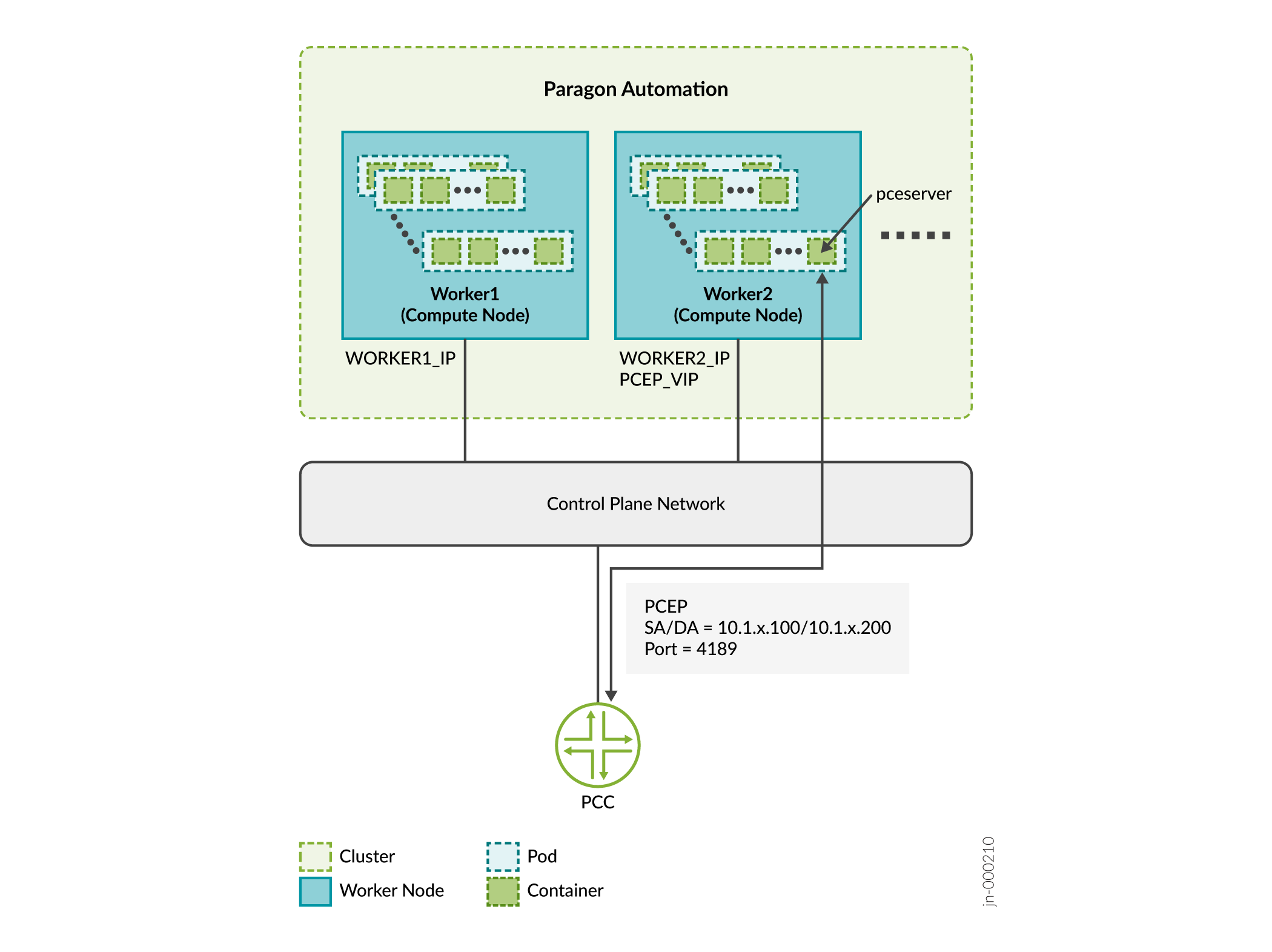
In this example:
-
Consider that Worker 1 is 10.1.x.3 and Worker 2 is 10.1.x.4.
-
SERVICE IP = PCEP VIP is 10.1.x.200
-
PCC_IP is 10.1.x.100
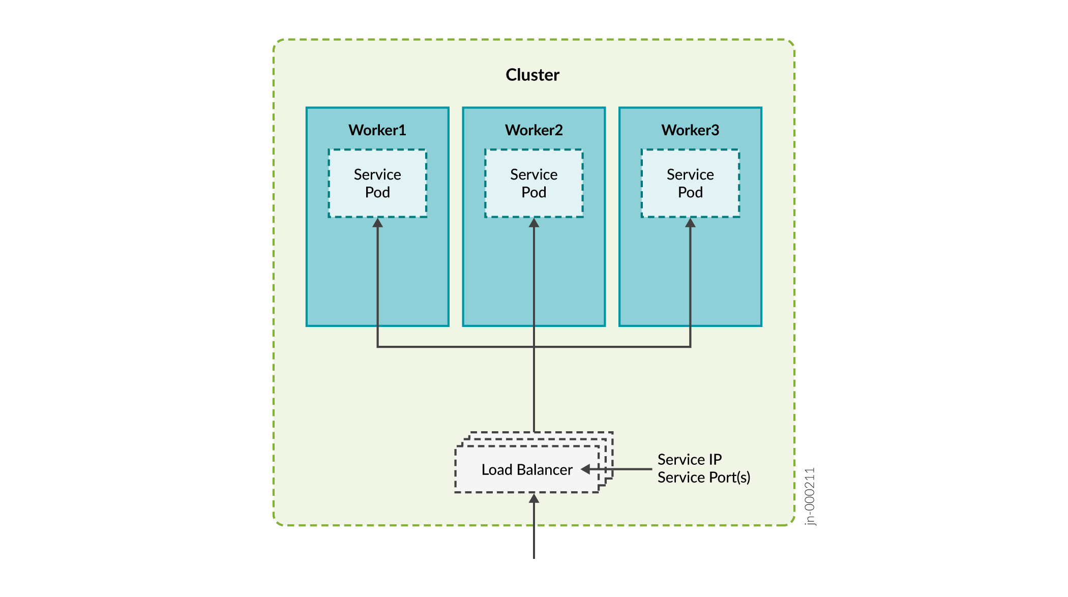
Paragon Automation services use one of two methods of exposing services outside the cluster:
-
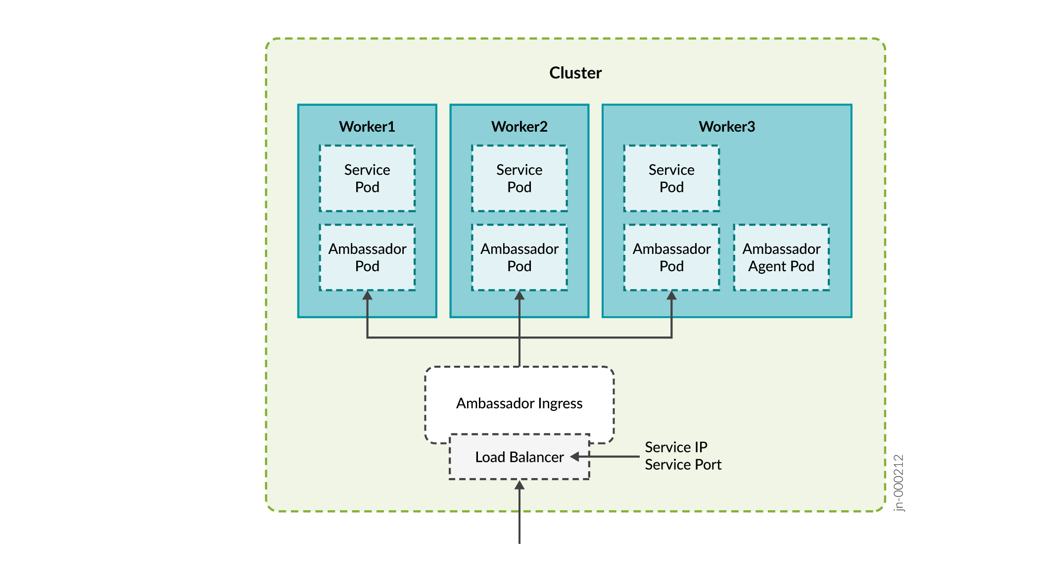
Load balancer—Each load balancer is associated with a specific IP address and routes external traffic to a specific service in the cluster. This is the default method for many Kubernetes installations in the cloud. The load balancer method supports multiple protocols and multiple ports per service. Each service has its own load balancer and IP address.
-
Paragon Automation uses the MetalLB load balancer. MetalLB simulates external load balancer by either managing virtual IP addresses in Layer 2 mode, or interacts with external router(s) in Layer 3 mode. MetalLB provides load-balancing infrastructure to the kubernetes cluster.
Services of type "LoadBalancer" will interact with the Kubernetes load-balancing infrastructure to assign an externally reachable IP address. Some services can share an external IP address.
-
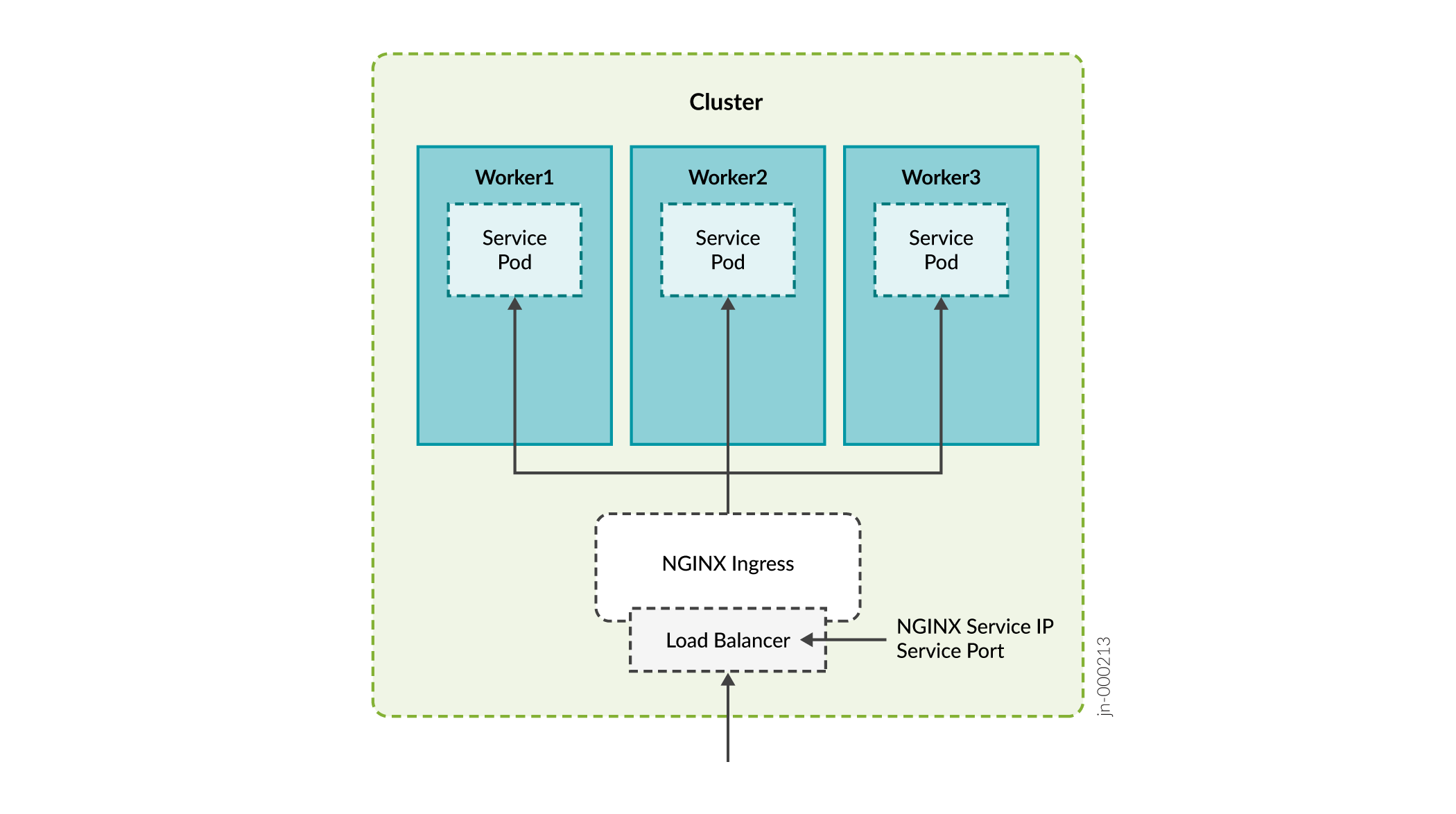
Ingress—The ingress method acts as a proxy to bring traffic into the cluster, and then uses internal service routing to route the traffic to its destination. Under the hood, this method also uses a load balancer service to expose itself to the world so it can act as that proxy.
Paragon Automation uses the following ingress proxies:
- Ambassador
- Nginx
Devices from outside the cluster need to access the following services and thus these services require a VIP address.
| Required VIP Address | Description | Load Balancer/Proxy |
|---|---|---|
|
Ingress controller |
Used for accessing the Paragon Automation GUI over the Web. Paragon Automation provides a common Web server that provides access to the components and applications. Access to the server is managed through the Kubernetes Ingress Controller. |
Ambassador MetalLB |
|
Paragon Insights services |
Used for Insights services such as syslog, DHCP relay, and JTI. |
MetalLB |
|
Paragon Pathfinder PCE server |
Used to establish PCEP sessions with devices in the network. |
MetalLB |
|
SNMP trap receiver proxy (Optional) |
User for the SNMP trap receiver proxy only if this functionality is required. |
MetalLB |
|
Infrastructure Nginx Ingress Controller |
Used as a proxy for the Paragon Pathfinder netflowd server and, optionally, the Paragon Pathfinder PCE server. The Nginx Ingress Controller needs a VIP within the MetalLB load balancer pool. This means that during the installation process you need to include this address as part of the LoadBalancer IP address ranges that you will be required to include while creating the configuration file. |
Nginx MetalLB |
|
Pathfinder Netflowd |
Used for Paragon Pathfinder netflowd server. Netflowd can use Nginx as proxy, in which case it will not require its own VIP address. |
MetalLB |
|
PCEP server (Optional) |
Used for the PCE server for MD5 authentication. |
- |
|
cRPD (Optional) |
Used to connect to the BGP Monitoring Protocol (BMP) pod for MD5 authentication. |
- |
Ports used by Ambassador:
-
HTTP 80 (TCP) redirect to HTTPS
-
HTTPS 443 (TCP)
-
Paragon Planner 7000 (TCP)
-
DCS/NETCONF initiated 7804 (TCP)
Ports used by Insights Services, Path Computation Element (PCE) server, and SNMP:
-
Insights Services
JTI — 4000 (UDP)
DHCP — (ZTP) 67 (UDP)
SYSLOG — 514 (UDP)
SNMP proxy — 162 (UDP)
-
PCE Server
PCEP — 4189 (TCP)
-
SNMP
SNMP Trap Receiver — 162 (UDP)
Ports used by Nginx Controller:
-
NetFlow 9000 (UDP)
-
PCEP 4189 (TCP)
Using Nginx for PCEP
During the installation process, you will be
asked whether you want to enable ingress proxy for PCEP. You can select from
None or Nginx-Ingress as the proxy for
the Path Computation Element (PCE) server.
If you select Nginx-Ingress as the proxy, you do not
need to configure the VIP for the PCE server described in Table 1. In this case, the VIP address for
Infrastructure Nginx Ingress Controller is used for the PCE server also. If
you choose to not use a netflowd proxy, the VIP for the Infrastructure Nginx
Ingress Controller is used for netflowd, as well.
The benefit of using Nginx is that you can use a single IP address for multiple services.
VIP Addresses for MD5 Authentication
You can configure MD5 authentication to secure PCEP sessions between the router and Paragon Pathfinder as well as ensure that the BMP service is peering with the correct BGP-LS router. Paragon Automation uses Multus to provide the secondary interface on the PCE server and BMP pod for direct access to the router. You need the following VIP addresses in the same subnet as your cluster nodes:
-
VIP address for the PCE server in the CIDR format
-
VIP address for cRPD in the CIDR format
The VIP address pool of the MetalLB load balancer must not contain these VIP addresses.
If you choose to configure MD5 authentication, you must additionally configure the authentication key and virtual IP addresses on the routers. You must also configure the authentication key in the Paragon Automation UI.
-
MD5 on PCEP sessions.—Configure the MD5 authentication key on the router and the Paragon Automation UI and VIP address on the router.
-
Configure the following in the Junos CLI:
user@pcc# set protocols pcep pce
                                            pce-id authentication-key
                                            pce-md5-key
user@pcc# set protocols pcep pce pce-id destination-ipv4-address vip-for-pce -
Enter the pce-md5-key authentication key in the MD5 String field in the Protocols:PCEP section on the Configuration > Devices > Edit Device Name page.
The MD5 authentication key must be less than or equal to 79 characters.
-
-
MD5 on cRPD— Determine the cRPD MD5 authentication key and configure the key and VIP address of cRPD on the router.
Determine or set the MD5 authentication key in the following ways.
Run the
confcommand script and enable MD5 authentication on cRPD. Search for thecrpd_auth_keyparameter in the config.yml file. If there is a key present, it indicates that cRPD is configured for MD5. For example:crpd_auth_key : northstar. You can use the key present in the config.yml file (or you can also edit the key) and enter it on the router.If no MD5 authentication key is present in the config.yml file, you must log in to cRPD and set the authentication key using one of the following commands:
set groups extra
                                                protocols bgp group name
                                                authentication-key
                                                crpd-md5-key
or
set protocols bgp group name
                                                authentication-key
                                                crpd-md5-key
The MD5 authentication key must be less than or equal to 79 characters.
Configure the router to enable MD5 for cRPD.
user@pcc#
                                    set protocols bgp group name neighbor
                                        vip-for-crpd authentication-key
                                        md5-key
You must identify all the required VIP addresses before you start the Paragon Automation installation process. You will be asked to enter these addresses as part of the installation process.
Configure Load Balancing
VIPs are managed in Layer 2 by default. When all cluster nodes are in the same broadcast domain, each VIP address is assigned to one cluster node at a time. Layer 2 mode provides fail-over of the VIP and does not provide actual load balancing. For true load balancing between the cluster nodes or if the nodes are in different broadcast domains, you must configure load balancing in Layer 3.
You must configure a BGP router to advertise the VIP address to the network. Make sure that the BGP router uses ECMP to balance TCP/IP sessions between different hosts. Connect the BGP router directly to the cluster nodes.
To configure load balancing on the cluster nodes, edit the config.yml file. For example:
metallb_config:
  peers:
    - peer-address: 192.x.x.1 ## address of BGP router
      peer-asn: 64501 ## autonomous system number of BGP router
      my-asn: 64500 ## ASN of cluster
  address-pools:
    - name: default
      protocol: bgp
      addresses:
        - 10.x.x.0/24
In this example, The BGP router at 192.x.x.1 is responsible for advertising reachability of the VIP addresses with the 10.x.x.0/24 prefix to the rest of the network. The cluster allocates the VIP address of this range and advertises the address for the cluster nodes that can handle the address.
Configure DNS Server (Optional)
You can access the main Web gateway either through the ingress controller's VIP address or through a hostname that is configured in the Domain Name System (DNS) server that resolves to the ingress controller's VIP address. You need to configure the DNS server only if you want to use a hostname to access the Web gateway.
Add the hostname to the DNS as an A, AAAA, or CNAME record. For lab and Proof of Concept (POC) setups, you can add the hostname to the /etc/hosts file on the cluster nodes.
