AP43 Components and Specifications
Figure 1 shows the components on the AP43.
Figure 1: AP43 Components
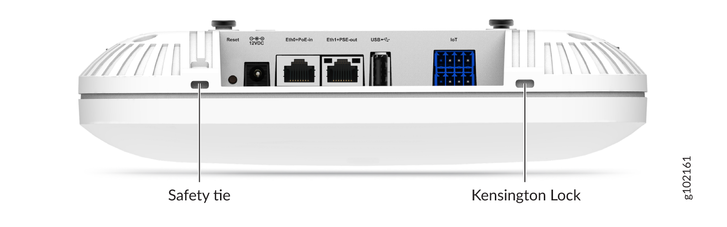
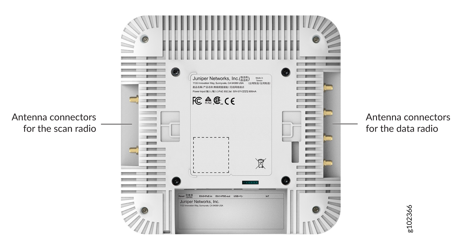
Figure 2 shows the antenna connectors on the AP43E.
Figure 2: Antenna Connectors on the AP43E
| Component | Description |
|---|---|
| Reset | A pinhole reset button that you can use to reset the AP configuration to the factory default. See Reset an AP to the Factory-Default Configuration. |
| 12VDC | Input for an optional
12 VDC
power supply.
You must order this power supply (part number: DC-01) separately. |
| Eth0+PoE-in | 100/1000/2500BASE-T RJ45 port that supports an 802.3at or 802.3bt PoE-powered device |
| Eth1+PSE-out | 10/100/1000BASE-T RJ45 port + 802.3af Power Sourcing Equipment (PSE) (if PoE-in is 802.3bt) |
| USB | USB 2.0 port |
| IoT |
8-pin port for digital input and output, analog input, and ground |
| Antenna connectors (available only in AP43E models) | Six reverse-polarity SubMiniature version A (RP-SMA) connectors (four dual-band for client radios; two dual-band for the third radio) |
| Kensington lock | Slot for a Kensington-style lock that you can use to secure the AP. |
| Safety tie | Slot for a safety tie that you can use to either secure or hold the AP in place |
| Status LED |
A multicolor status LED to indicate the status of the AP and to help troubleshoot issues. See Troubleshoot a Juniper Access Point. |
For AP43 specifications, see the AP43 Datasheet.