Mount the AP61 Access Point
You can mount the AP61 either on a wall or on a pole using two methods—flush mount or articulating mount.
Mounting Brackets for AP61
- Mounting Brackets and Accessories for Flush Mount
- Mounting Brackets and Accessories for Articulating Mount
We ship the AP61 with the articulating and flush mount brackets. You can order the flush mount brackets separately. Table 1 lists the part numbers for the mounting brackets.
| Part Number | Description |
|---|---|
| APOUTBR-ART | Articulating mount brackets |
| APOUTBR-FM | Flush mount brackets |
Mounting Brackets and Accessories for Flush Mount
The mounting accessories for flush mount include the following:
-
One flush mount bracket (part number: APOUTBR-FM)
-
Two hose clamps
-
Four M6 screws
-
Four sets of M6 screws, washers, and spring washers
-
Five sets of anchors and screws
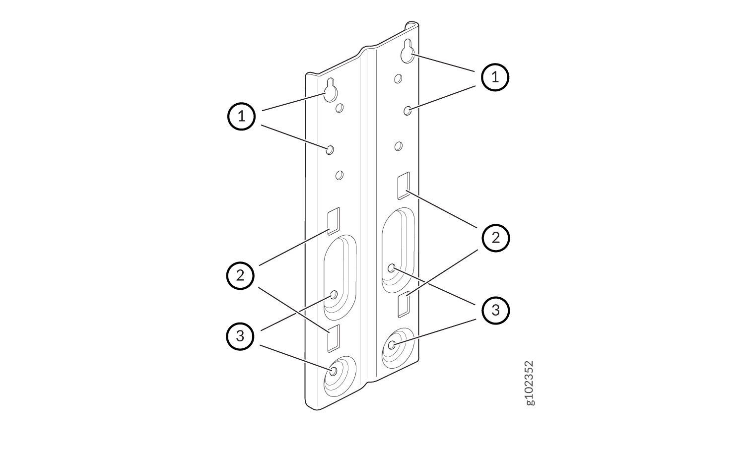
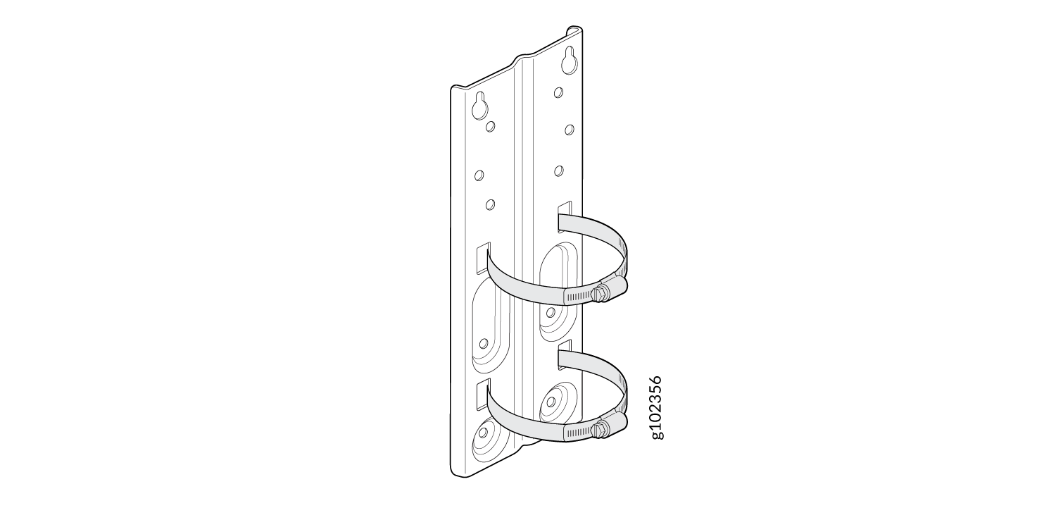
| 1—Screw holes to use for mounting an AP61 on a wall | 2—Holes to use for attaching hose clamps |
| 3—Screw holes to use for attaching the bracket to an AP61 |
Mounting Brackets and Accessories for Articulating Mount
The mounting accessories for articulating mount include the following:
One articulation pole
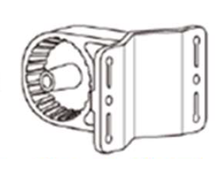
One T-form bracket
One W-Bar
-
Two M8x80 screw bolts
-
One M8x90 screw bolt and nut
-
Four M6x16 screws
-
Four M6x10 screws
-
Four wood screws
-
Four wood or gyprock plugs
-
Eight washers
-
Eight spring washers
-
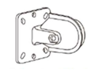
One metal plate assembly with RT2 mount
Connect the Grounding Cable
We recommend that you ground the AP before mounting it on a wall or pole. The AP61 has a single-hole protective grounding terminal on the rear. Use this grounding terminal to ground the AP.
To ground the AP61:
- Remove the screw from the grounding terminal.
- Place the grounding lug attached to the grounding cable over the grounding terminal. We recommend a minimum of 18-AWG wire for the AP.
- Secure the grounding cable lug to the grounding terminal with the screw.
Mount the AP61 on a Wall (Flush Mount)
-
Attach the APOUTBR-FM flush mount bracket to the AP by using the four
screws, washers, and spring washers provided along with the AP.
Use the bracket screw holes marked with callout #3 in Figure 1.Figure 2: Attach the APOUTBR-FM Flush Mount Bracket to an AP61
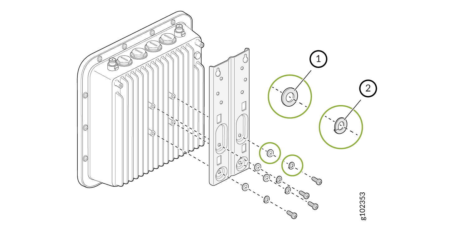
1—Washer 2—Spring washer -
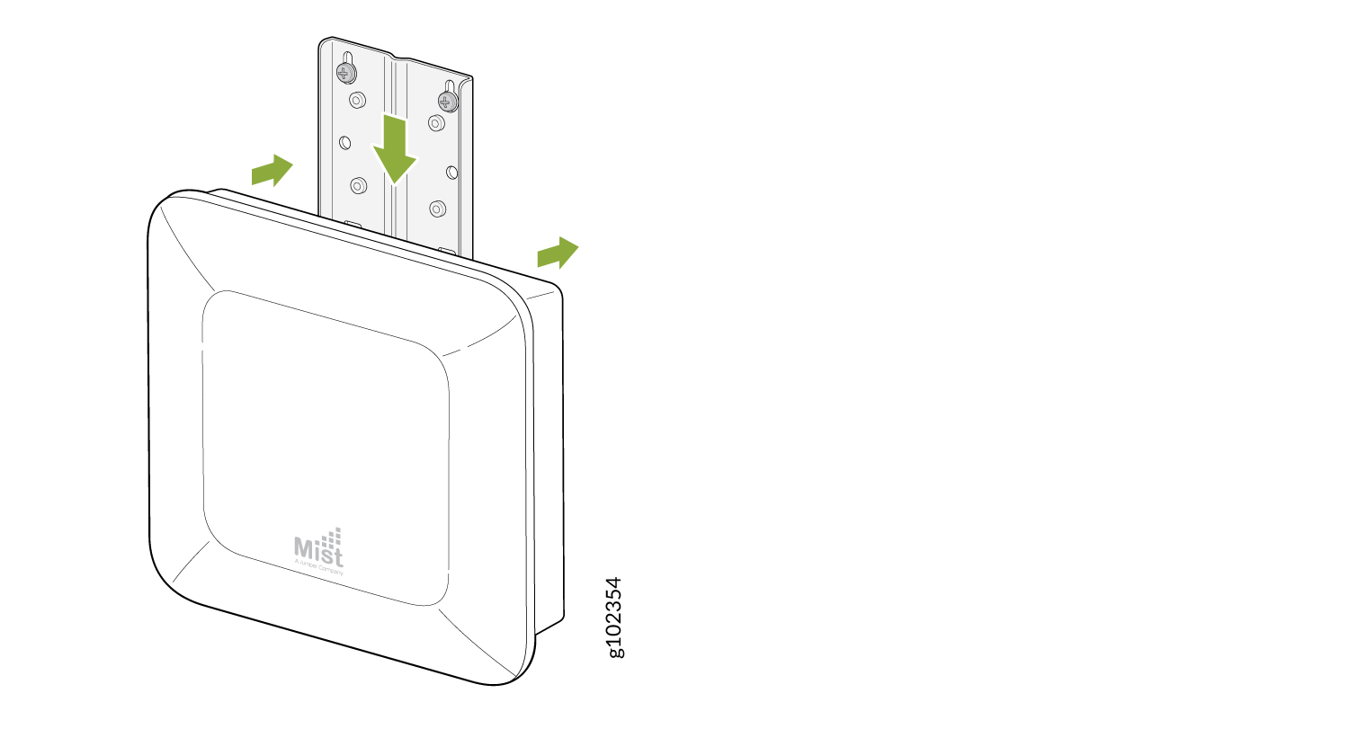
Position the AP such that the two screws that you inserted into the wall in
Step 1 fit into the holes in the bracket. Slide the AP
downward
so that the screws lock in place.
Figure 3: Mount an AP61 on a Wall (Flush Mount)
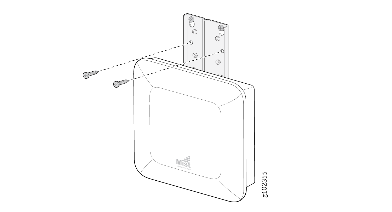
-
Insert the other two screws through the bracket into the holes in the wall
and then tighten all the four screws.
Figure 4: Secure the AP61 to a Wall
Mount the AP61 on a Pole (Flush Mount)
-
Attach the hose clamps to the APOUTBR-FM flush mount bracket. Use a
screwdriver to release the hose clamps and then pass the hose clamps through
the slots on the flush mount
bracket.
Figure 1 shows
the slots that you can use.
Ensure that the open end of the hose clamps faces outward.Figure 5: Attach Hose Clamps to the APOUTBR-FM Flush Mount Bracket
-
Attach the APOUTBR-FM flush mount bracket with the hose clamps to the AP by
using the four screws, washers, and spring washers provided along with the
AP.
Figure 6: Attach the APOUTBR-FM Flush Mount Bracket to an AP61
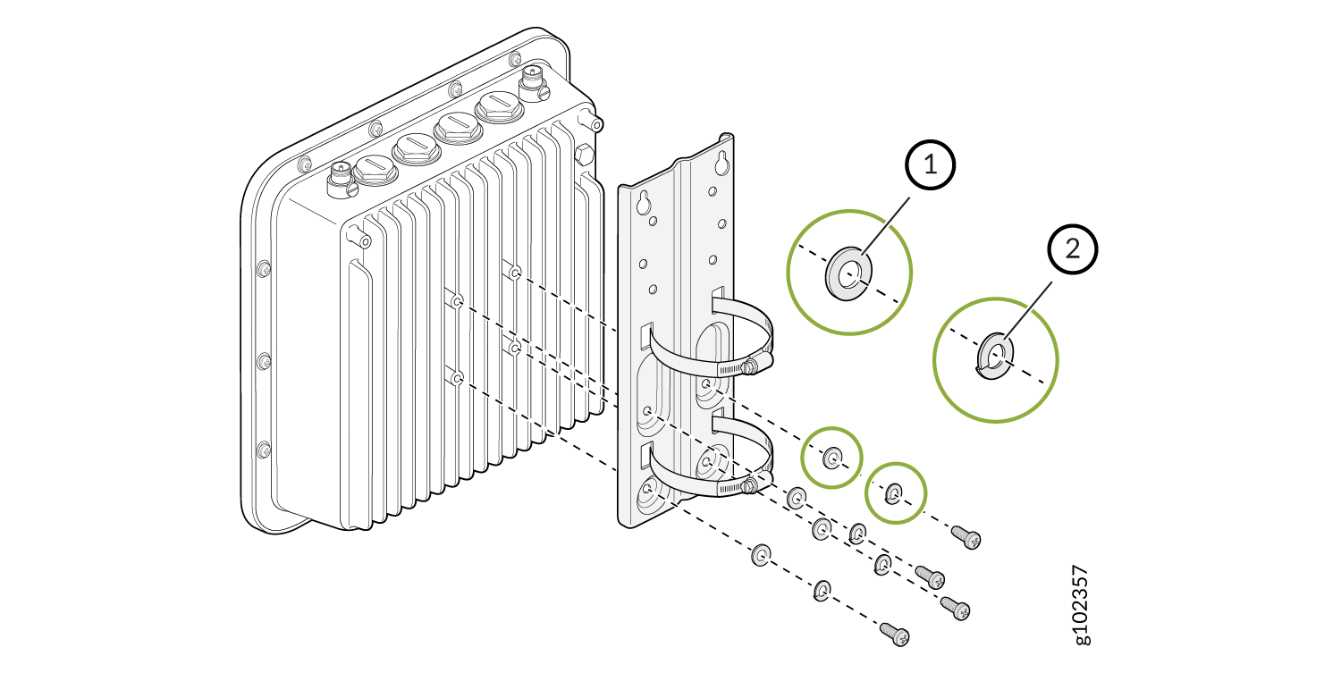
1—Washer 2—Spring washer -
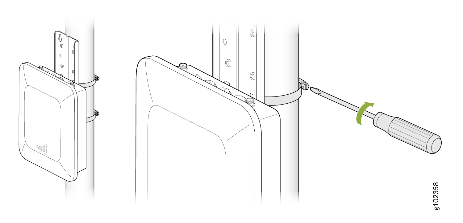
Mount the AP on the pole. Wind the open end of the hose clamps around the
pole and tighten the hose clamp screws by using a screwdriver. Tighten the
screws until the AP and bracket assembly are secured in
place.
Figure 7: Mount an AP61 on a Pole (Flush Mount)
Mount the AP61 on a Wall (Articulating Mount)
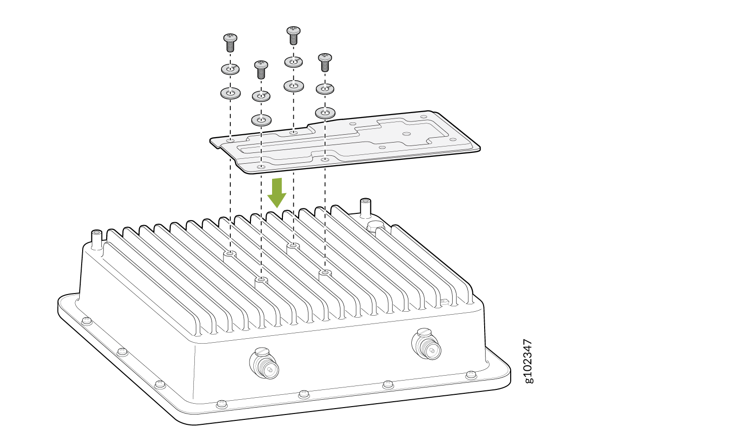
-
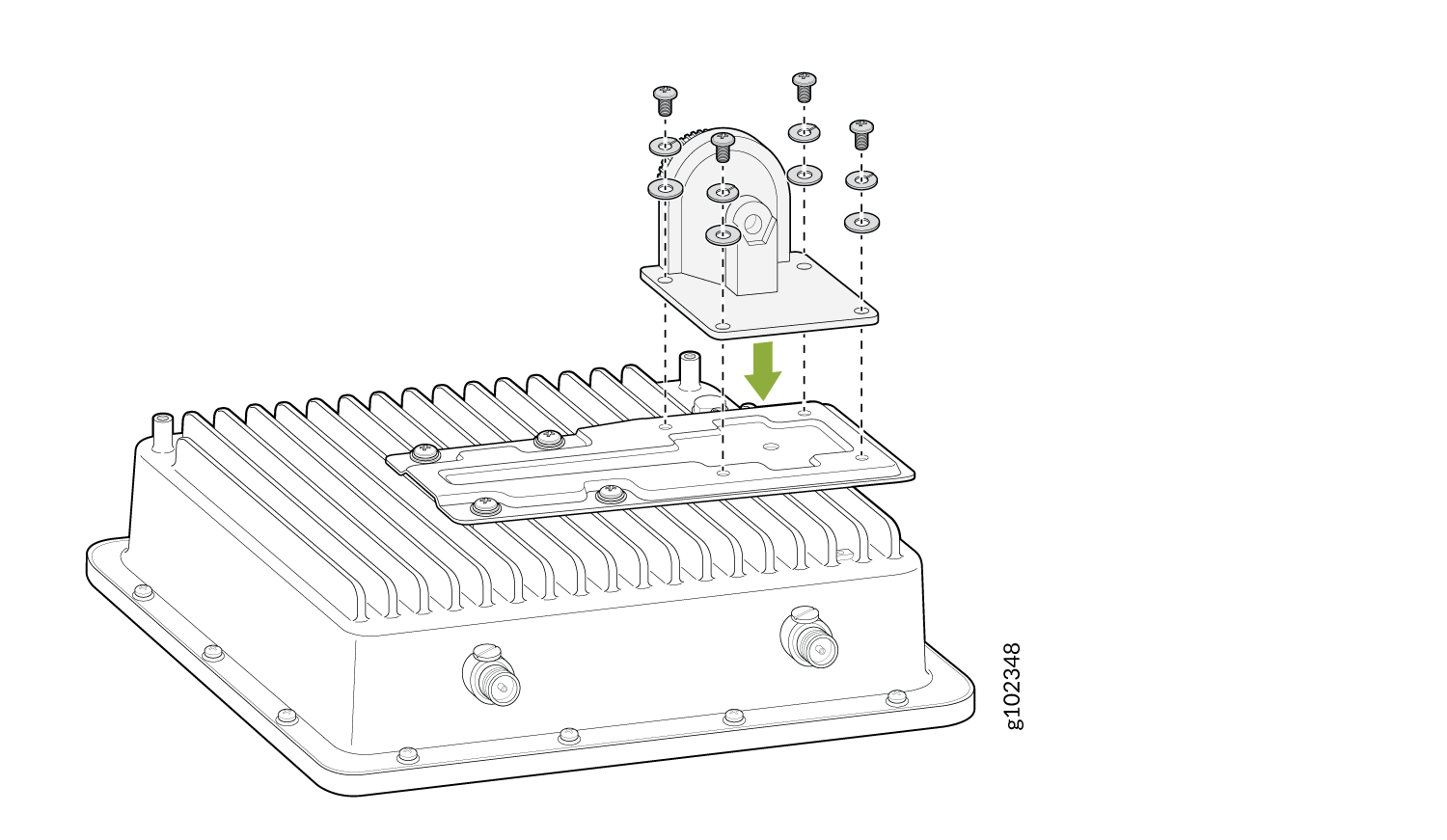
Attach the metal plate assembly to the AP by using the four M6x16 screws,
washers, and spring
washers.
Figure 8: Attach the Metal Plate Assembly to an AP61
-
Attach the articulating mount bracket to the metal plate assembly by using
the four M6x10 screws, washers, and spring washers.
Figure 9: Attach the Articulating Bracket to the Metal Plate Assembly on an AP61
-
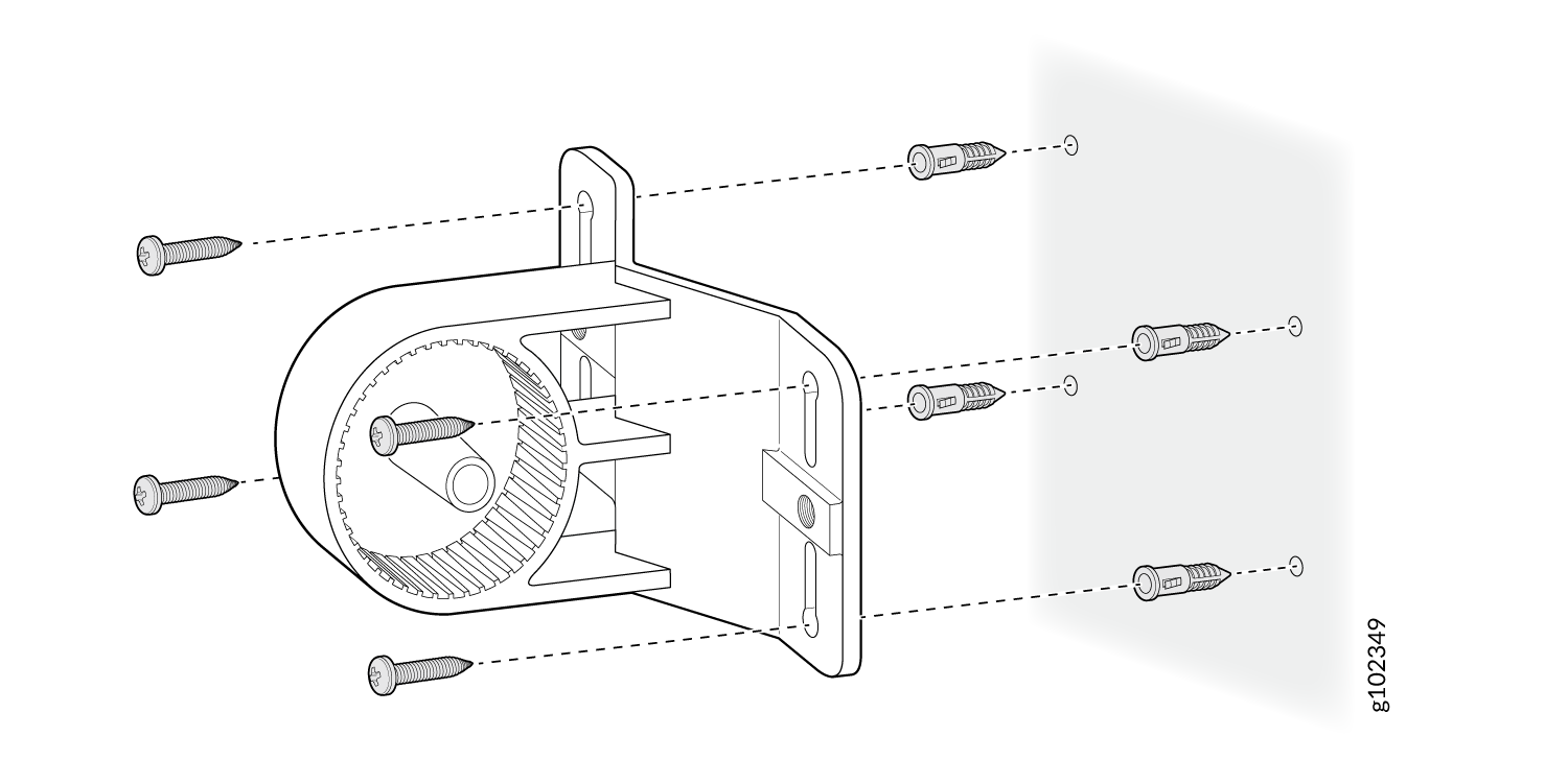
Install the T-form bracket on the wall by using wood or gyprock
screws.
Figure 10: Install the T-Form Bracket on the Wall
Mount the AP61 on a Pole (Articulating Mount)
-
Attach the metal plate to the AP by using the four M6x16 screws, washers,
and spring washers.
Figure 12: Attach the Metal Plate to an AP61
-
Attach the articulating bracket to the metal plate by using the four M6x10
screws, washers, and spring washers.
Figure 13: Attach the Articulating Bracket to the Metal Plate on an AP61
-
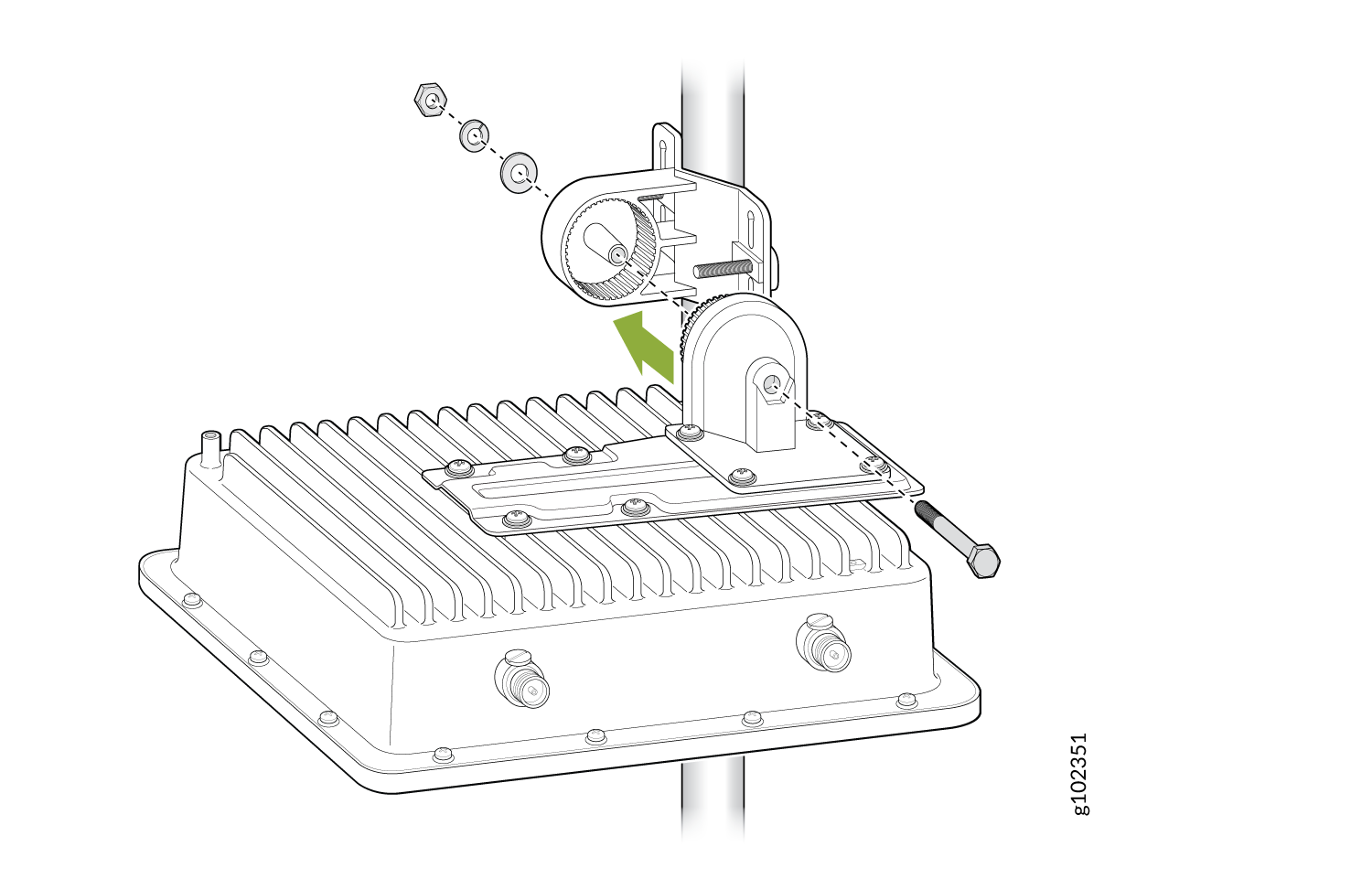
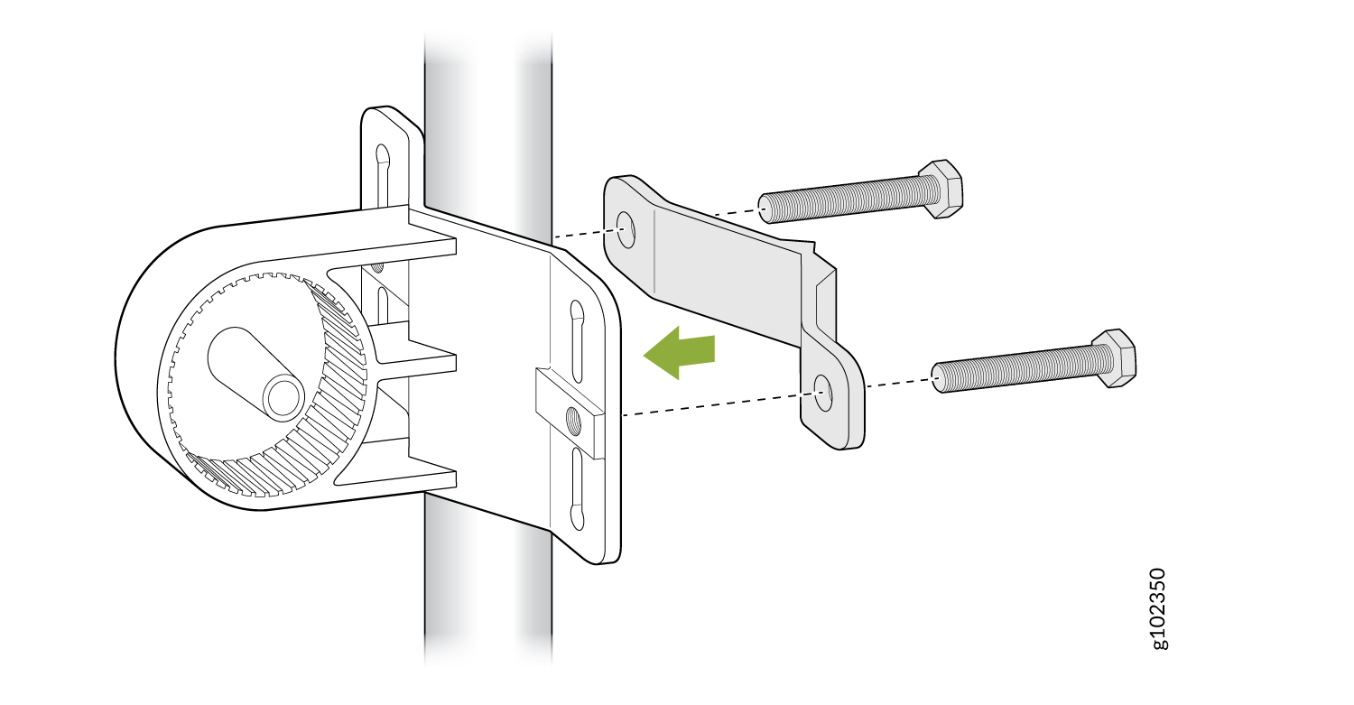
Install the T-form bracket on the pole by using the provided screw bolts
and nuts.
Figure 14: Install the T-Form Bracket on the Pole
-
Attach the articulating bracket to the T-form bracket by using M8x80
screws.
Figure 15: Mount the AP61 on a Pole (Articulating Mount)